

Page 1

SECURED SERIES
™
HUB
PLUS
CONTROL MODULE/
MODEM COMPATIBLE
FEATURES, PROGRAMMING AND WIRING GUIDE
500 USERS
1000 TRANSACTION BUFFERED AUDIT TRAIL
SUPPORTS TWO FRONT-ENDS FOR IN/OUT OPERATION
PROGRAMMABLE FROM KEYPAD ON HUB, OR P.C.
PRINT LIVE AUDIT TRAIL
EIGHT TIME ZONES (PROGRAMMABLE WITH P.C. SOFTWARE)
SIXTEEN HOLIDAY TIME ZONES (PROGRAMMABLE WITH P.C. SOFTWARE)
AUTO UNLOCK TIME ZONES
FIRST IN AUTO-UNLOCK
REMOTE ACCESSIBLE VIA MODEM
FORCED DOOR ALARM RELAY/TIMER
PROPPED DOOR RELAY/TIMER
ALARM ZONE SHUNTING RELAY
TIMED EGRESS INPUT
NON-VOLATILE EEPROM MEMORY
“DURESS CODE” CAPABLE WITH KEYPAD
The Secured Series System by IEI is a two part, single door, access control system. When used with
a locking device, it can control access to that particular door. A one door system would consist of one HUB
control module, and up to two front end readers. The door may require a reader on the inside as well as
the outside of the door (for logging of in and out transactions),but the HUB control module can only control
one door.
The HUB is where all memory is stored, and all outputs originate. The HUB control module reads data
sent to it from the front end, determines if access should be granted or not, and energizes the proper outputs. All relay outputs are located internal to the HUB controller, as well as communication ports for networking, an internal clock, a keypad for programming, and memory chips to store user information and
transaction log data.
If you wish, you can run communication wires from HUB to HUB for the purpose of sending data,
ie.,user codes, card or touch chip number information from one stand-alone HUB to the next. This is
referred to as networking. Networking will also allow you to transfer data from any HUB in the system to a
serial printer, for example sending the transaction log information, or the list of code, card or chip numbers.
You can also run a network cable from the HUB designated as “Door #1” to a personal computer. This
will allow the owner to easily manipulate important information from HUB to HUB or simply program in and
out information pertaining to the system from one location, the computer. With a computer networked into
the system the owner can now view the list of people by name when looking at the transaction log, and
also assign time zones and holidays limiting certain users to a timed schedule. The personal computer
makes programming easier than from the HUB keypad. This will also require the IEI Secured Series
Software, Model # PCSFTWR. Up to eight HUB controllers may be networked into the system, or on one
personal computer or serial printer.
The HUB control module comes equipped with an infra-red transmitter mounted just to the left of the
red/green bi-color light. You can see the window that the data is transferred out of just above the numbered digits on the HUB keypad. IEI’s hand held IR-printer, (model# IR-PRINT) will allow you to retrieve
the transaction log or user list from the front of each HUB. WIRELESS! Using the IR port disables the use
of the system with a personal computer, or serial printer.
Page 2

Table Of Contents
What is a Front End?...............................................................................
Location of HUB.......................................................................................
What you need to know about installing a HUB...................................
Parts Checklist.........................................................................................
Testing the system..................................................................................
Wiring the Front End...............................................................................
Propped Door Relay................................................................................
Forced Door Relay...................................................................................
Alarm Shunt Relay...................................................................................
Auto Re-Lock...........................................................................................
Request to Exit Switch............................................................................
Networking...............................................................................................
Transferring of HUB control data...........................................................
DC wiring diagrams.................................................................................
AC wiring diagrams.................................................................................
Printing features and programming......................................................
Setting up printer to receive data..........................................................
Modem wiring and programming...........................................................
Programming............................................................................................
Troubleshooting guide............................................................................
Programming Options Chart..................................................................
Accessories.............................................................................................
Product specifications............................................................................
2
PG. 3
PG. 3
PG. 3
PG. 4
PG. 5
PG. 6
PG. 7
PG. 8
PG. 9
PG. 9
PG. 10
PG. 11
PG. 12
PG. 13
PG. 15
PG. 16
PG. 20
PG. 21
PG. 24
PG. 29
PG. 31
PG. 32
PG. 33
Page 3

What is a “FRONT END”?
A front end is the device which you choose to place outside the door. IEI manufactures several to
choose from, keypads, magnetic card readers, proximity card readers, touch chip readers. No programming is done from the front end, only at the HUB controller.
Location of HUBS
Once you have established which type of device you need, and how many doors will be equipped
with electronic access, a location must be found for the HUB controllers. Whether you have a one
door system or an eight, IEI recommends that the HUB or HUBs be located in a secure but convenient location. If you are planning a system with two or more HUBs, IEI recommends that you place
all the HUB controllers in the same location if possible.
What you need to know about installing a HUB
The HUB controller can be mounted in a standard size, single-gang electrical box. If you find
space in a single-gang box insufficient for all the wiring, try a double-gang electrical box with a mud
ring. Arecommendation for systems that have two or more HUBs, is to purchase a can or cabinet.
Mounting at your work bench consists of cutting a 2¾ inch by 2 inch hole in cabinet door for each
HUB. The HUB controllers should be far enough apart to fit a small flat-head screwdriver in between
units, in order to access the screw terminal block at each HUB control. With the HUB controllers
mounted in door of cabinet, you can program from the keypads, all located in a single location.
Open door of cabinet and look at the back of the HUB controllers, all the wiring is now accessible,
easy to work with, easy to install, easy for troubleshooting, and makes for a clean job.
IEI manufactures a one HUB cabinet with a 12VDC power supply all mounted at the factory,
model #PSW/ENC-12V. A 12 x 14 cabinet will house four (4) HUB controls, but power supplies
must be in another cabinet.
3
Power for the Secured Series access control system can be from 12 volts AC/DC, up to 24 volts
AC/DC. Choosing the correct power supply for your application is important! One HUB controller will
power one or two front ends, but will only be capable of controlling one locking device. To calculate
current draw requirements for the Secured Series system,determine what front end you will be using
and view chart on current draw on page 32. Add current draw from front end to 125 milliamps.
Multiply this total by the number of doors in your system. Locking devices must also be taken into
consideration when using the same power supply to power your locks. Adding the current draw for
the locking devices to your total will give you the total current draw on your power supply.
Power for HUB controller
Page 4
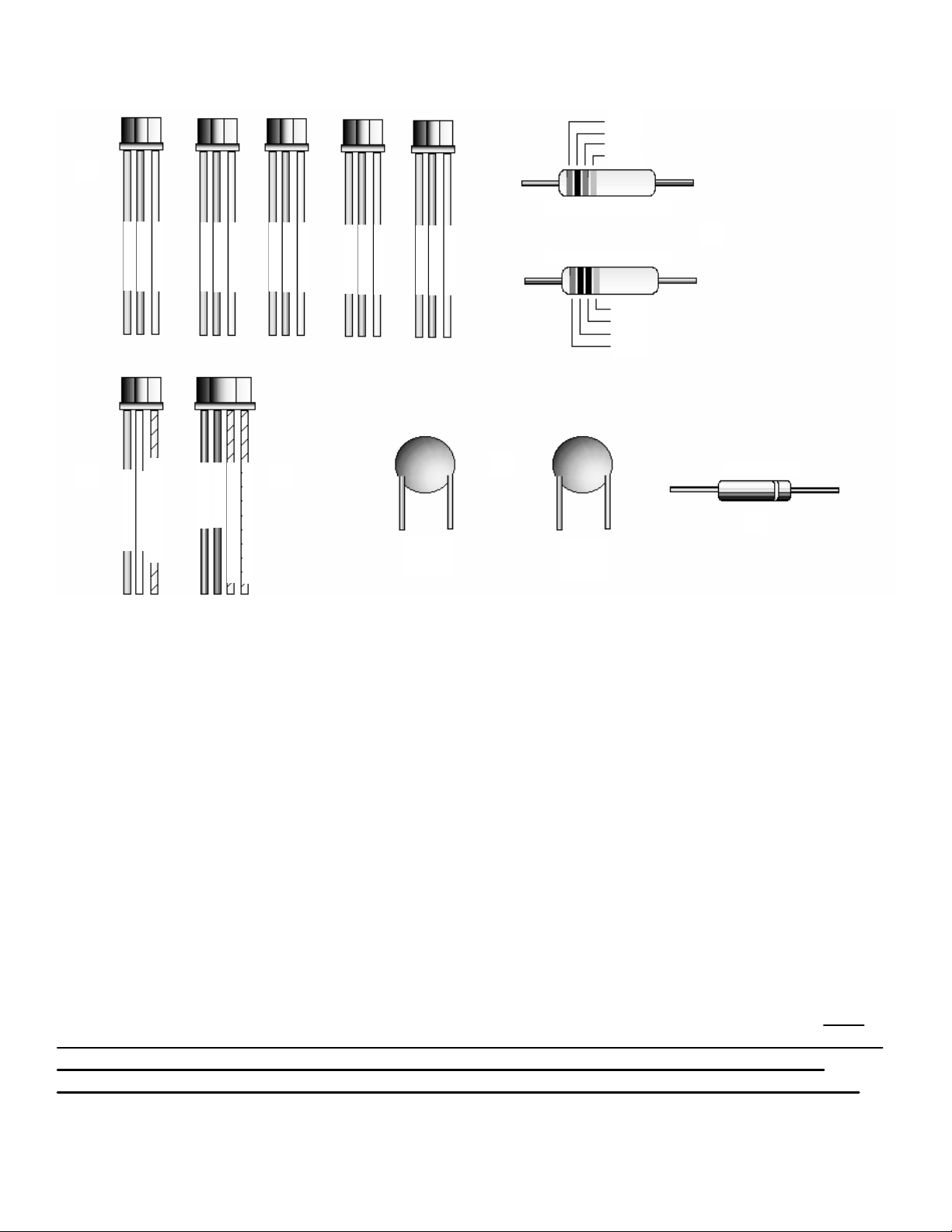
PARTS CHECK LIST
Additional parts included with the HUB
plus
Control Module are as follows:
5 ea. Three conductor harness with blue, green, and gray wires. 1 ea. will be used for the
Propped door, Forced door, and the Alarm shunt relay. The remaining 2 will be used when networking HUBs together, or when connecting HUB to a serial printer or personal computer.
2 ea. 1/4 watt resistors. One 10 ohm resistor, marked with a brown, black, and black stripe and
one 100 ohm resistor with a brown, black, and brown stripe. These are to be used when using AC
as a power source. Use the 10 ohm resistor with 12VAC, and the 100 ohm resistor with 24VAC.
2 ea. Metal Oxide Varistors. These are used when using AC or DC as a power source. One will
be connected at V+ and V- on the terminal strip of the HUB control module, and the other will be
connected across the terminals on the locking device. No polarity need be observed.
1 ea. 1N4004 Diode. This component is wired across the locking device terminals when using DC
as a power source. Silver band towards positive side of lock
1 ea. Three conductor harness with brown, white, and white\orange wires. This harness is to be
connected to a request to exit switch (normally open), and a door contact (normally closed). If no
door contacts are to be used, then the white wire and the white\orange wire must be shorted
together
, otherwise the request to exit switch will not engage the locking device when
pressed, and the transaction log will display “Door
Ajar” when a valid entry has occurred.
1 ea. Four conductor harness with black, red, white\black, and white\yellow wires. This harness is
used to connect the HUB to the front end.
g
r
e
e
n
b
l
u
e
g
r
a
y
g
r
e
e
n
b
l
u
e
g
r
a
y
g
r
e
e
n
b
l
u
e
g
r
a
y
g
r
e
e
n
b
l
u
e
g
r
a
y
g
r
e
e
n
b
l
u
e
g
r
a
y
b
r
o
w
n
w
h
i
t
e
w
h
t
/
o
r
g
b
l
a
c
k
r
e
d
w
h
t
/
b
l
a
c
k
w
h
t
/
y
e
l
metal
oxide
varistor
metal
oxide
varistor
10 ohm 1/4 watt resistor
100 ohm 1/4 watt resistor
1N4004 diode
4
Brown
Black
Brown
Gold
Gold
Black
Black
Brown
A.
B.
E. F.
C.
D.
A.
B.
C.
D.
E.
F.
Page 5

SECURED SERIES DEFA ULTS
Door-Gard Secured Series keypads are designed for easy inst allation in a minimum amount of time. The following default s have
been factory programmed.
Master Code (user 1) 1234
*
Main Relay will energize for 5 secs.
Keypress Feedback O n
Propped door relay will energize af ter 30 secs.
Forced door relay will energize for 10 secs.
Printer Output Port RS-232 Port (Port A on Hub Control Module #1)
If default s must be changed or additional functions are desired, please refer to PROGRAMMING FROM THE HUB (see p a g e
24).
LED INDICATO R S
The following is a list of the LED operations on the Hub Control Module
Yellow LED
Slow blink Program mode active/T ransaction log almost full indicator
Rapid blink Program mode verify
S teady Program mode error
V ery rapid blink Memory (EEProm) erase in progress
Bi-color LED
Solid red Main relay not energized
Solid green Main relay energized
Rapid green blink User dump or log dump in progress
Slow green/yellow blink User dat a being sent (yellow LED also blinks slow)
Slow red/green blink Unit is in receive mode or user dat a is being received
Slow green blink Unit is in A u t o L o c k \ U n l o c k m o d e
TESTING THE SYSTEM
Testing The Hub Control Module
1. Connect the positive (+) lead of your power supply to the screw terminal (TS1) +V input on the Hub Control Module.
2. Connect the negative (-) lead of your power supply to the screw terminal (TS1) -V input on the Hub Control Module.
3. T urn on your power supply.
4. The bi-color (red and green) LED on the face of the Hub Control Module should be red.
5. Press 7890#123456*. If all 12 keypresses are verified, the Hub Control Module will enter self test mode. The bi-color LED
should now turn green. The red LED flashes alternately with the yellow LED and then both will turn of f. The sounder will
then beep 3 times, p ause, then beep once more. If this does not happen, try to enter self test mode again by pressing
7890#123456
*.
6. Enter the master code of 1234*. The red LED will turn of f and the green LED will turn on for 5 seconds while the main relay
energizes. Refer to programming section (see p age 24) to program your system.
Testing The Front End Module
1. Power down your Hub Control Module when connecting any Front End Module.
2. Refer to appropriate Front End Module wiring diagram (see p age 6) for proper connection to Hub Control Module.
3. T urn on your power supply.
4. Once the Front End is properly powered a red LED (except for the Ruggedized) will illuminate on the front of the unit.
5. If the Front End Module has a keyp ad, then press 7890#123456*. If all 12 keypresses have been verified, the Front End
Module will enter self test mode. See the following for proper self test mode Front End indicators:
Indoor/Weather Resist ant Keyp ads- LED s will sequence across and then the yellow LED will flash until a key is
pressed.
Mullion Keyp ad- LED s will sequence across and then the far left green LED will flash until a key is pressed.
Card Reader/Keypad- LED s will sequence across, sounder beeps twice and then the yellow LED will flash until a key is
pressed.
Ruggedized Keypad- The sounder will beep twice. Press any key to exit self test mode.
W eather Proof Keyp ad- The LED will alternately flash and then turn of f, af ter which, the sounder will beep twice. Press
any key to exit self test mode.
6. Enter the master code of 1234*(except on the Card, Proximity, or Touch Reader). The red LED (except for the Ruggedized )
will turn green and the main relay on the Hub Control will energize. Refer to programming section (see p age 24) to program
your system.
5
Page 6
Voltmeter
Electrical
Tape
Electrical
Tape
Front
End
Insulator
BLACK
RED
BLACK/WHITE
BLACK\YELLOW
Drain
Wire
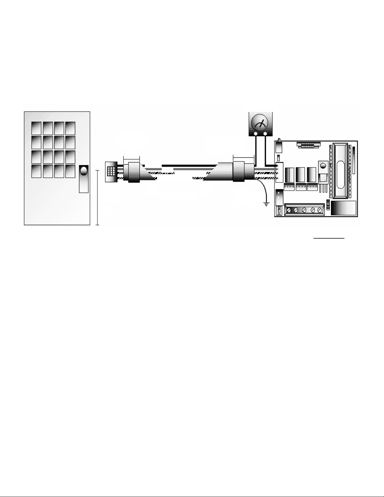
WIRING THE FRONT END
A front end is the device which you choose to place outside the door. IEI manufactures several
to choose from; keypads, magnetic card readers, proximity card readers, and touch chip readers.
No programming is done at the front end.
Choosing the correct front end for the application is important. IEI manufactures light traffic and
heavy traffic devices. If you are not sure which front end to utilize, please call us at 1-800-343-9502.
TESTING THE FRONT END FOR GROUND POTENTIAL DIFFERENCES
Wiring the front end to the HUB control unit requires a four conductor,stranded and shielded
cable to be wired between two units. Maximum lengths are as follows:
At the HUB, connect the four conductor cable to the four pin connector on the Hub control relay
board, as shown in the diagram above. The drain wire at the HUB controller must be attached to
ground, also the foil shield should be cut back with the insulator and taped with electrical tape.
Ground is the V- terminal on TS1 if the power supply is grounded. At the front end, the drain wire
and foil shield is cut back with the insulator and taped with electrical tape. The four conductor harness connects into the four pin connector in the front end. Both wire harnesses are connected to
each other color to color.
22 AWG stranded : 250 feet
20 AWG stranded : 500 feet
18 AWG stranded : 1000 feet
48”
If the front end reader is mounted to the metal frame of the building, a ground potential test
should be run. This test is important because a ground potential difference between the power supply ground and the ground on the metal frame of a building can render the system inoperable. The
front end should first be installed and the power supply grounded and turned off. Now set up a
meter to read DC voltage. At HUB control separate the black wire of the four conductor cable from
the wire running to the front end and attach the meter in series with the two wires per diagram
above. If the meter shows more than one volt then the front end must either be insulated from the
frame or the ground wire of the reader must be removed. Setup meter to read AC voltage and
repeat test. On the front end you will find the grounding wire screwed to the case at one end and
plugged into the circuit board on the other end. If you have any questions about this procedure
please call IEI technical support, 1-800-343-9502.
6
Page 7
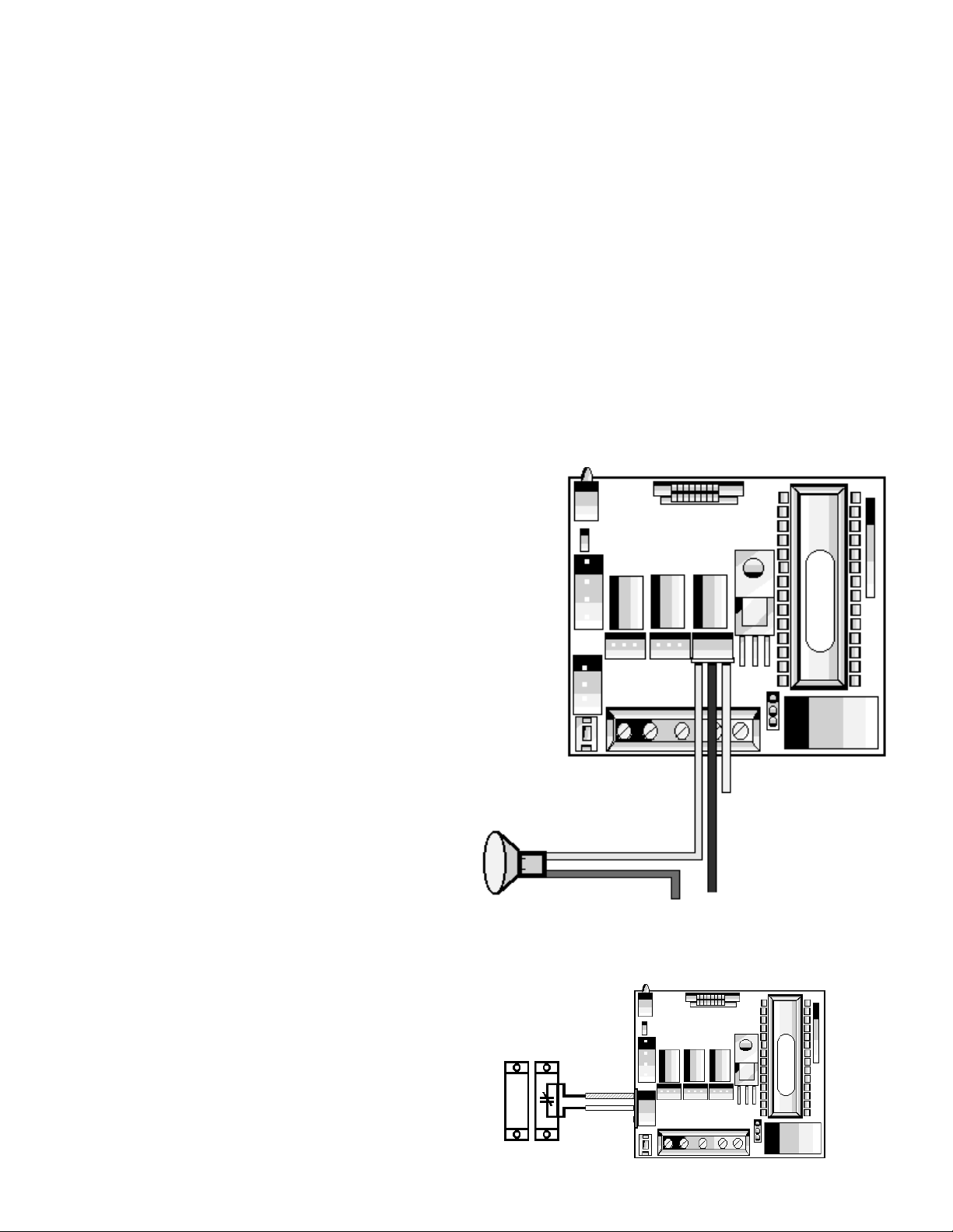
Propped Door Relay
This output is utilized to inform personnel that the door is being held, or propped open, after a
valid entry. To accomplish this, the Hub
plus
Control Module comes equipped with a relay and an
internal timer circuit that is designated for this purpose. The relay is rated to handle one (1) amp of
current at either 12 volts or 24 volts, type AC or DC, and turns on or off one leg of power to a warning device. Warning device not included with IEI equipment.
1. Connect the three conductor harness with the green,
blue, and gray wire to the propped door relay jack as
shown in diagram A.
2. Connect green wire to V+ on sounder.
3. Connect blue wire to V+ from power supply.
4. Connect V- from power supply to V- on sounder.
5. Gray wire is not used.
DIAGRAM A
HUB
PLUS
CONTROL RELAY BOARD
V-
V+
V+
GREEN (NO)
BLUE (C)
GRAY (NC) NOT USED
Programming the Propped Door Relay
To program how long the door can be propped open
before the alarm is tripped, Program as follows:
1. Enter programming mode. Press 99 # (master code) *
2. Verify HUB is in programming, yellow light should be
flashing slowly.
To
Power Supply
To incorporate this feature into your system, simply locate one of the five connectors, each one
with three (3) wires, green, blue, and gray, located in the box with the Hub
plus
Control Module. With
the HUB powered down, unlatch the keypad from the plastic housing and slide the two (2) printed
circuit boards out of housing. With the circuit boards out, you can now separate the two (2) boards,
exposing the connectors as shown in Diagram A. If the propped door relay is energized, the event
will be logged in the transaction buffer.
3. Press 44 # (time) # 0 # **, time represents how
long the relay stays de-energized, 10 to 900 seconds
4. Press * to exit program mode, yellow light
should not be flashing.
Propped door time must be programmed in intervals of 10 seconds, ie. 10, 30, 60,... up to 900
seconds.
NOTE: This feature requires that you utilize the
door contact (input) per diagram B.
door contact
white wire
with orange
stripe
white wire
DIAGRAM B.
Propped
Door
Relay
Wiring the Propped Door Relay
7
Page 8
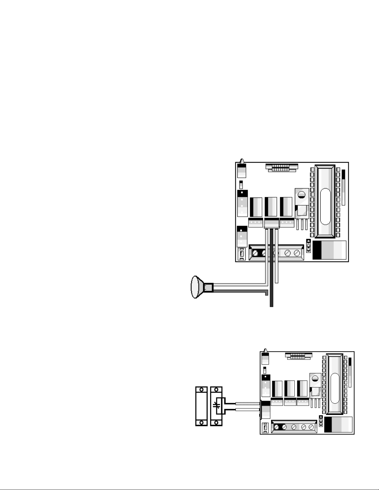
Forced Door Relay
Forced
Door
Relay
This output is utilized to inform personnel that the door had been opened without authorization. To
accomplish this, the Hub
plus
Control Module comes equipped with a relay and an internal timer circuit that is designated for this purpose. The relay is rated to handle one (1) amp of current at either
12 volts or 24 volts, type AC or DC, and turns on or off one leg of power to a warning device.
Warning device not included with IEI equipment.
To incorporate this feature into your system, simply locate one of the five connectors, each one
with three (3) wires, green, blue, and gray, located in the box with the Hub
plus
Control Module. With
the HUB powered down, unlatch the keypad from the plastic housing and slide the two (2) printed
circuit boards out of housing. With the circuit boards out, you can now separate the two (2) boards,
exposing the connectors as shown in Diagram A. If the forced door relay is energized, the event will
be logged in the transaction buffer.
Wiring the Forced Door Relay
1. Connect the three conductor harness with the green, blue,
and gray wire to the forced door relay jack as shown in diagram A.
2. Connect green wire to V+ on siren.
3. Connect blue wire to V+ from power supply.
4. Connect V- from power supply to V- on sounder.
5. Gray wire is not used.
HUB
PLUS
CONTROL RELAY BOARD
DIAGRAM A.
To
Power Supply
V+
V+
V-
GRAY (NC) NOT USED
GREEN (NO)
BLUE (C)
Programming the Forced Door Relay
To program the time forced door output stays
energized, Program as follows:
1. Enter programming mode. Press 99 # (master
code) *
2. Verify HUB is in programming, yellow light
should be flashing slowly.
3. Press 45 # (time) # 0 # * *, time represents how
long the relay stays energized, 10 to 900 seconds,
or you may press 00 for a latched output, requiring a valid code to reset output.
4. Press * to exit program mode, yellow light
should not be flashing.
white wire
with orange
stripe
white wire
NOTE: This feature requires that you utilize the
door contact (input) per diagram B.
DIAGRAM B.
door contact
8
Page 9

Alarm Shunt Relay
Alarm
Shunt
Relay
green
blue
gray (not used)
door contact
DIAGRAM A
DIAGRAM B.
HUB
PLUS
CONTROL RELAY BOARD
The shunt relay may be necessary to use when a security
system or other type of system has already been in existence.
The shunt relay would keep the alarm from activating when
the door is opened. No programming required, the HUB controller will activate the shunt relay automatically with any valid
access or egress.
To incorporate this feature into your system, simply locate
one of the five connectors, each one with three (3) wires,
green, blue, and gray, located in the box with the Hub
plus
Control Module. With the HUB powered down, unlatch the
keypad from the plastic housing and slide the two (2) printed
circuit boards out of housing. With the circuit boards out, you
can now separate the two (2) boards, exposing the connectors as shown in diagram A.
Wiring the Alarm Shunt Relay
1. Connect the three conductor harness with the green, blue,
and gray wire to the alarm shunt relay jack as shown in diagram A.
2. Connect green wire to “Common” side of door contact.
3. Connect blue wire to “Normally Open” side of door contact.
4. Make a parallel connection to the green and blue wires,(as
shown in diagram A.), and run the leads to the alarm panel.
NOTE: This feature requires that you utilize the door contact (input) per diagram B.
door contact
white wire with
orange stripe
white wire
Auto Re-Lock
Auto Re-Lock solves the problem of people
“tailgating” in behind those using valid access
protocol, allowing the programmer the opportunity to set a long door open time. This feature
over-rides the main relay timer, resetting the
door open time as soon as the HUB sees the
door open. In many situations, you will find yourself programming a long door open time, this
allows people carrying packages enough time to
get from the front end (reader) to the door and
open it before the timer runs out. Other people may only require a few seconds to do the same task,
without an auto re-lock, the door would be left unlocked long enough for people to tailgate in behind
you. No programming is necessary, after a valid access or egress, the HUB control monitoring the
door contact sees the door switch open and drops the main relay immediately, disengaging the lock
which you will notice always locking behind you, whether you take three seconds to get to the door
or ten seconds.NOTE: This feature requires that you utilize the door contact (input) per dia-
gram B.
To alarm panel
To alarm panel
9
Page 10
Each HUB control module may
be wired to monitor a remote
switching device, and is meant to
be installed on the safe side of a
door. This is a momentary input
that will engage the main relay for
the same amount of time that the
master code is set for. This input
requires a momentary closure
between two wires at the HUB
enabling you the freedom to use
several devices in a parallel circuit.
This function can be stored in the
transaction log for future viewing. A
remote button may be placed at a
receptionist desk, press to exit
switch on the inside of a door, or a
passive infra red detector, allowing
free and convenient egress. You
may opt to install a second front
end. This would be for higher security where personnel may need to
be monitored entering and exiting a
building or a room. A remote button
can still be used to open a door
even if you have used a second
front end on the door. Their is no
programming required, just wire
according to one of the two
Diagram A.
Diagram B.
REQUEST TO EXIT SWITCH
following wiring diagrams which applies to your application. Locate the cable harness
with the brown, white, and white and orange stripe wires. This three wire harness is
in the box that the HUB came in. Plug the harness into the white connector next to
the program switch (sw1). If you do not wish to install the door contacts per dia-
gram A, then you must twist the white wire and the white and orange striped
wires together, see diagram B.
Door Contact
Brown
White
White\Orange
Normally
Open
Switch
Normally
Open
Switch
Brown
White
White\Orange
10
Page 11
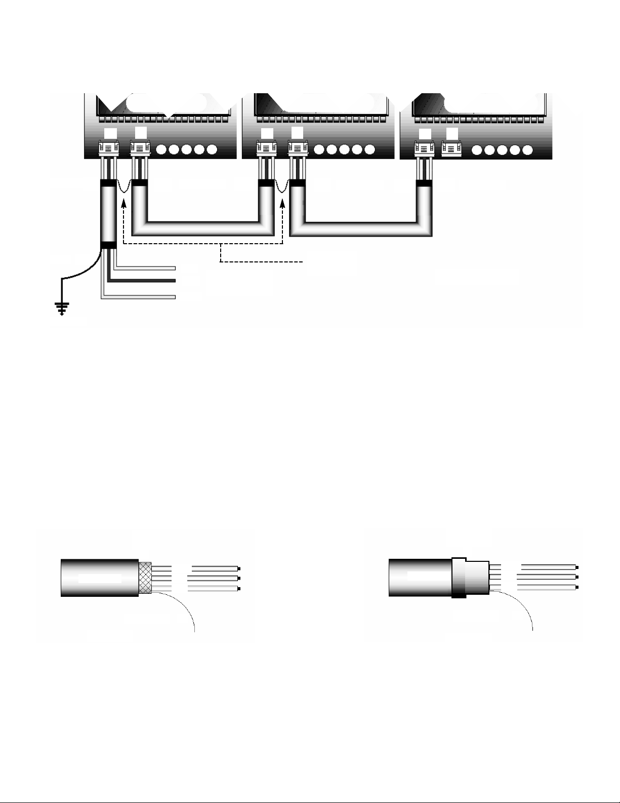
NETWORKING
USING SHIELDED CABLES
A
C
A
C
A
C
blue
green
gray
drain wire
earth ground
electrical tape
electrical tape
electrical tape
electrical tape
to serial printer
or computer
GROUNDING THE NETWORK CABLE SHIELD
Once you have run the network cable it will need to have the shields grounded. Under the insulator there is a foil shield that protects the wire from any data, RF, or AC that might be induced on the
lines (see diagram B.). After you you strip back the insulator, remove the exposed shield, leaving
only the wires. You will have exposed the wires with individual insulators and a bare wire called a
“drain wire”, they will be used so do not cut them. Tape over the exposed foil with electrical tape to
prevent it from shorting to any wires accidentally not covered properly during installation,(see diagram C.) The shield is now grounded!
DIAGRAM B.
DIAGRAM C.
The network cable provides the data buss that information can be transferred along. This cable is
run between HUBs and will enable the user to transfer all, or selected user information from one
programmed HUB to another. It can also be connected to a personal computer, or a serial printer.
To wire, locate two of the three conductor harness with the green, blue, and gray wire. Now, at
the HUB designated as door #1, locate the two white male connectors ( on the buffer board ), called
port “A” and port “C”(see diagram A.). Insert one three conductor harness into each port on all the
HUBs you wish to network. The wires extending from port “A” of HUB #1 will be wired to a personal
computer or a serial printer. The wires from port “C” of HUB #1 will go to HUB#2 port “A”. Connect
the harnesses between port “C” of HUB #2 to port “A” of HUB #3 color to color.(see diagram A.) If
the cable exits a cabinet, or must be run more than a few feet, then you must protect the data with a
shielded cable. The shield must be connected to ground at one end, the other end is to be “floating”, or un-grounded.
INSULATOR
FOIL
SHIELD
DRAIN WIRE
green
blue
gray
INSULATOR
ELECTRICAL
TAPE
DRAIN WIRE
green
blue
gray
Diagram A.
11
Drain wires
connected
Page 12

TRANSFERRING OF HUB CONTROL D ATA
Before a Hub Control can receive dat a it must be put into a receive mode. While a Hub control is waiting to receive or is receiv ing dat a, the green and red LED s will alternately blink. The receiving Hub will remain in receive mode until a key is pressed; at
which time it will return to normal operations. No transactions can be processed from a front end while a Hub is in receive mode.
SET HUB TO RECEIVE DATA
At receiving Hub:
1. Enter programming mode Press 99 # (master code) *(yellow LED flashes slowly)
2. Set Hub to receive Press 29 # 0 # 0 #
* *
SET HUB TO SEND DATA
When data is sent a range of user numbers may be specified or you may copy all of the Hub data at once. While a Hub Control
is sending dat a the green LED will blink slowly . When the transfer is complete, the sending Hub will return to programming
mode.
At sending Hub:
To send all of the Hub dat a at once:
1. Enter programming mode Press 99 # (master code) *(yellow LED flashes slowly)
2. Set Hub to send dat a Press 21 # 0 # 0 #
* *
This new command will copy all system p arameters (relay time, propped door time, etc.) to the receiving Hub along with the pro grammed users. The time and date must still be programmed at the receiving Hub. This procedure will copy the door number from
the sending Hub to the receiving Hub. The door number must be reprogrammed at the receiving Hub af ter the transfer has been
completed.
To send a group of user numbers:
1. Enter programming mode Press 99 # (master code) *(yellow LED flashes slowly)
2. Set Hub to send dat a Press 20 # (FFF) # (LLL) #
* *
FFF = First user number to transfer
LLL = Last user number to transfer
12
WIRING OF COMMUNICATION PORTS
Page 13

Power
Supply
V+
V-
V+ V- NC C NO
V+ V- NC C NO
TS-1
TS-1
P5
Jumper
P5 Jumper
Relay
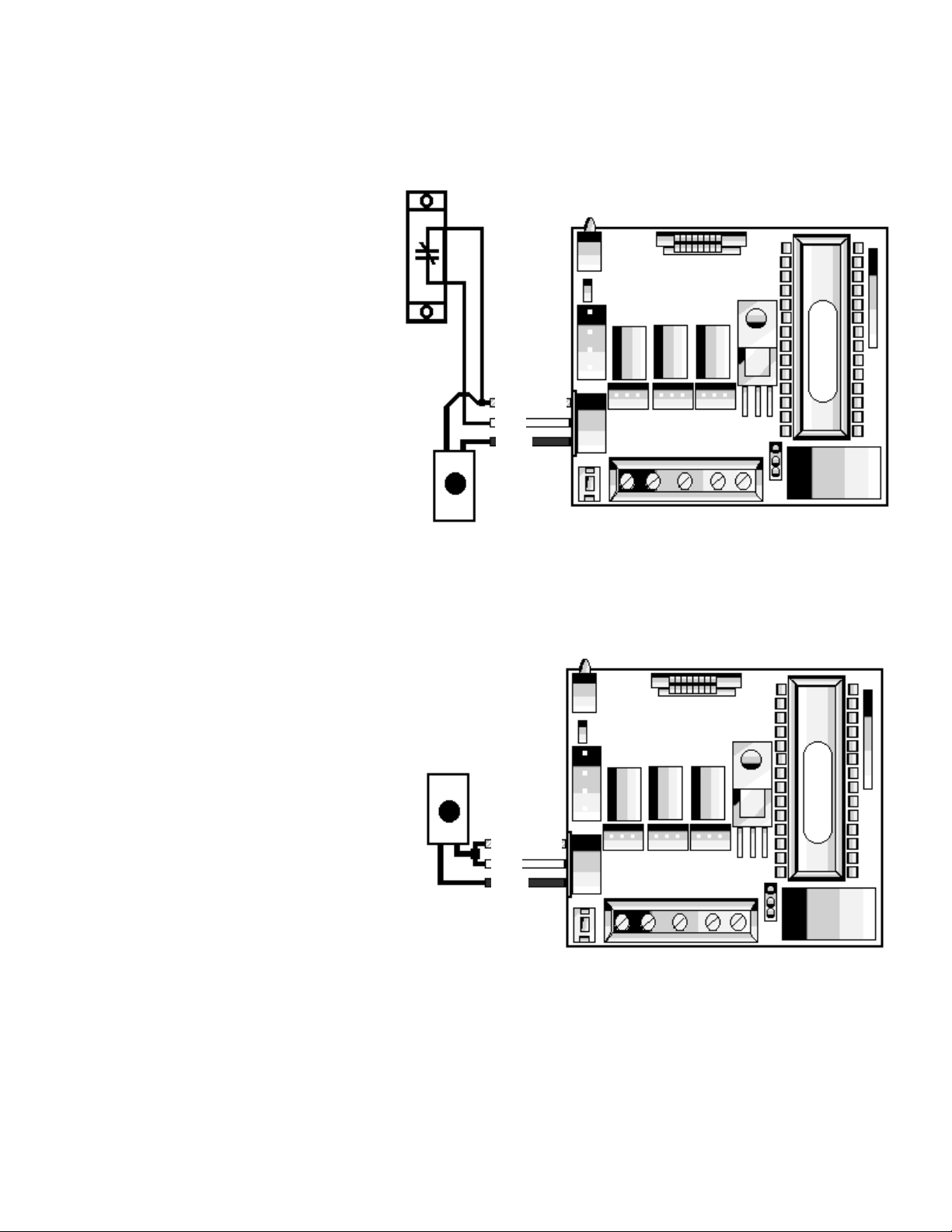
Relay
1. Determine what voltage you will be using to power hubs.
2. When using 12-15 VDC, place P5 jumper in position 1.
3. When using 15-24 VDC, place P5 jumper in position 2.
Position 1
Position 2
12-15 VDC 15-24 VDC
4. Connect V+ from power supply to V+ on TS-1.
5. Connect V- from power supply to V- on TS-1.
6. With power on, the red led will turn on.
7. Enter “1234*”, the red led will turn off, and the green led will turn on for 5 seconds.
After 5 seconds the green led will turn off and the red led will turn on, signifying an
armed status. Relay will “click” upon entering “1234*”.
8. Turn power off and proceed with wiring locking devices.
P5 Jumper
Grounding the power supply
Any time you network HUBs together, care must be taken to insure that the power
supplies are grounded properly. If you are installing more than one power supply for a
system, all power supplies must be tied to a common ground by running a common
line between the supply ground lug terminals. If the supplies do not have ground
lugs, run a wire between the DC negative terminals on the output from the units.
13
DC Power Requirements / Wiring Diagrams
HUB #1 HUB #2
Page 14

V+
V-
V+ V- NC C NO
TS-1
P5
Jumper
Relay
1. Determine what voltage you will be using to power hub
2. When using 12-15 VDC, place P5 jumper in position 1.
3. When using 15-24 VDC, place P5 jumper in position 2.
Position 1
Position 2
12-15 VDC
15-24 VDC
4. Connect V+ from power supply to V+ on TS-1.
5. Connect a jumper wire from V+ to C on TS-1.
6. Connect V+ from strike to NO on TS-1.
7. Connect diode across locking device terminals; Striped end on V+ at lock, and the
other end to V- on
locking device.
8. Connect V- from strike to V- on TS-1.
9. Connect V- from power supply to V- on TS-1.
10. With power on, the red led will turn on.
11. Enter “1234*”, the red led will turn off, and the green led will turn on for 5 seconds.
After 5 seconds the green led will turn off and the red led will turn on, signifying an
armed status. Relay will “click” upon entering “1234*”.
P5 Jumper
Power
Supply
Strike*
Diode
Grounding the power supply
Any time you network HUBs together, care must be taken to insure that the power
supplies are grounded properly. If you are installing more than one power supply for a
system, all power supplies must be tied to a common ground by running a common
line between the supply ground lug terminals. If the supplies do not have ground
lugs, run a wire between the DC negative terminals on the output from the units.
14
*NOTE: When wiring a magnetic
lock, use diagram above with the
following exception:
6. Connect V+ from magnetic
lock to NC on TS-1.
DC Power Requirements / Wiring Diagrams
Page 15

Transformers can have AC or DC power as an output. The output from a transformer, whether
AC or DC, is unfiltered, unregulated and has certain limitations. Many electrical environments are
susceptible to having transients, electrical spikes, and surges. Such noisy electrical systems can
induce a glitch in the program of the HUB controller. Some situations to look for are listed below.
Do not use transformer power in a system that networks HUBs together
, or on a system
that will be used with a personal computer. Using transformer power alone without a filter/regula-
tor circuit card will be acceptable in some locations. Make sure to follow the wiring diagram above
for this application. IEI has provided two M.O.V.’s and two different value resistors to use in this
application. The hardware packet will provide the two resistors and the M.O.V.. One ten ohm resistor
with brown, black, black color bands will be used for 12 volt AC application only, and one 100 ohm
resistor with the brown, black, brown color bands will be used for 24 volt AC applications only. These
are provided to add protection to the HUB systems, since transformers usually have little if any transient protection. If the bands are hard to see, please meter the resistors for the correct value.
The HUB controller needs to be set up for the voltage you decide to use. Find P5 pin rail and
select the proper pins to short together with the jumper (See diagram B.). You will find P5 is shown
in diagram A. next to the terminal strip.
Resistor
Door
Strike
Metal
Oxide
Varistor
Transformer
Buildings that utilize back-up electrical generators. (Hospitals, Nursing Homes, etc.)
When using power that also feeds the motor controller of a gate, or an overhead door.
In a building with heavy machinery like elevators, and other large three-phase motors,
welders, large industrial refrigerators, an AC units with large condensers.
When using a proximity reader as a front end, you must
use a filtered and regulated
12V DC power supply.
Diagram B.
3
2
1
12-24VAC
P5
Diagram A.
TS1
15
Metal
Oxide
Varistor
AC Power Requirements / Wiring Diagrams
Page 16

Printing Features and Programming
Hub Control Front V iew
The following connections are
shown for most st andard serial
printers. Refer to your printer
manual for exact connections.
Location of InfraRed (IR) LED.
W ireless handheld printer must
be held near LED for proper
printing.
A
C
DB-9
Signal ground
Data out
Data in
DB-25
Signal ground
Data out
Data in
Pin
5
3
2
Pin
7
2
3
Wire
Green
Blue
Gray
Wire
Green
Blue
Gray
Ground
Hub Control
Communication Board
PROGRAMMING THE HUB CONTROL UNITS TO PRINT
Before the HUB can send data, you must program the following commands at each HUB.
• Enter programming mode at HUB by pressing 99 # master code *, the yellow light should be flashing.
• Press 43 # 0 # 01 up to 08 # ** sets door number
• Press 42 # mmddyy # day # ** sets the month day and year, day is 1 for
Sunday, 2 is for Monday...
• Press 41 # hhmm # 0 # ** sets the clock in military time ( 24 hour configuration).
• Press 31 # 3 # 0 # ** sets printer output for Infra-red port
• Press 31 # 3 # 1 # ** sets printer output for RS-232 Port A (System Default)
The printing feature offers the ability of retrieving reports from the system. Each HUB controller is
capable of sending the data stored in memory to three different types of equipment. The reports can be
sent to a personal computer, a hard wired serial printer, or the IEI infra-red printer model # IR-PRINT. Both
the serial and infra-red printers will require the user to go to each HUB in the system and use the keypad in
order to select the report desired. The Print Live feature allows you to view the transaction log as the
events occur with a serial printer. This feature can not be used with the infra-red printer. The print live command sends only the transaction log to a serial printer and will only be able to accommodate one HUB per
system. Each HUB is capable of storing up to one thousand transactions in memory. As the system is
being used the buffer takes and holds all the data in a “first in/first out” type of memory. This means that
when the buffer is full of transactions it will “bump” the oldest transaction out of the system.
16
Door #01
9/14/96
1 17:50 user 002 in
2 17:49 user 010 out
3 17:48 user 052 print
4 17:46 access denied
5 17:30 forced door
Page 17

The HUB can indicate that the buffer is 80% at capacity with a warning light. If the log almost full
warning is programmed “ON” and the transaction log has 799 transactions stored, the yellow light
on the HUB will flash once every ten seconds. The warning will continue until the log is erased,
dumped, or the self test sequence is entered at HUB. To program the log almost full warning follow
the programming steps below:
• At HUB press 99 # master code *, HUB should now be in programming mode, ( slow
flashing yellow light).
• Now press 31 # 11 # 1 # **
• Asolid yellow light indicates the command did not take, start over or call technical support
• Now exit programming mode by pressing the * button. The yellow light should not be flashing.
• Pressing 31 # 11 # 0 # **will disable feature.
PRINT LIVE
Print live is a feature that can be programmed into a HUB enabling the unit to transmit the log
data directly to a serial printer. The report that is generated by using the system also gets stored
into the memory buffer for future viewing. Print live can be programmed into any HUB in a network.
If more than one HUB tries to print at once, the data will be garbled at the printer, although the data
will still be available from the transaction buffer. This function is not capable of being used with the
infra-red printer. To program the HUB to print live follow the programming steps below:
• At HUB press 99 # master code *, HUB should now be in programming mode, ( slow flashing
yellow light).
• Now press 31 # 10 # 1 # **.
• Asolid yellow light indicates the command did not take, try again before calling technical sup-
port.
• Now exit programming mode by pressing the * button, The yellow light should not be flashing.
• • Pressing 31 # 10 # 0 # ** will disable function.
SELECTING THE INFORMATION THAT WILL SHOW IN THE LOG
Not every transaction will be necessary for viewing by the user. In this case IEI has provided
a way of ignoring the un-desired transactions. Certain transactions may be ignored by programming
those events out of the logs criteria. To program the HUB to ignore those transactions which are not
needed follow the programming steps below :
•At HUB press 99 # master code *, HUB should now be in programming mode, ( slow flashing
yellow light).
•Now press 73 # event # 0/1 # ** Asolid yellow light indicates the command did not take, start
over or call technical support.
•Now exit programming mode by pressing the * button, The yellow light should not be flashing.
Where the 0/1 is shown in the programming process is the on off directive for the HUB. This
means that if you press a “0” at this point that transaction will not be logged, or if you press a “1”
the transaction will be restored and the log will retain the event. The “event” is a two digit number
that represents a specific transaction. A list of the events that are logged are listed on the next
page.
17
Log Almost Full Warning
Page 18

01 - access denied 16 - print
02 - program denied 17 - in ( user xxx entered )
03 - program mode 18 - out (user xxx egresses )
04 - request to exit (Rex) 19 - bad time zone ( valid user tried to
05 - door ajar get access outside time zone)
06 - door closed 20 - toggle on
07 - forced door 21 - toggle off
08 - log erased 22 - first in / auto-unlock
09 - duress 23 - relock
All transactions are programmed at the factory to be logged. When a HUB is defaulted back to
its factory settings, the user may wish to program the events that should not be logged back out.
LOGGING “ACCESS DENIED”
When someone tries to gain access and has not been programmed for access at that door, the
log records the event as “access denied”. The person may have pressed the wrong code by accident or swiped the wrong card. You may or may not wish to know this type of information so IEI
have made provisions allowing this type of transaction to also be ignored. To program the HUB for
this option follow the steps below:
• Enter programming mode at HUB by pressing 99 # master code *, the yellow light should be
flashing slow.
• Press 31 # 06 # 0 # ** to ignore the transaction .
OR, press 31 # 06 # 1 # ** to log this type of transaction Asolid yellow light indicates the com-
mand did not take, start over or call technical support.
• Press * in order to exit program mode, yellow light should not be flashing.
PRINT LIST OF USERS
Both the serial printer and the infra red printer can be used to retrieve a list containing all the
user access information. This is done at each HUB controller and can only show the information
from that specific HUB. The HUB unit is a stand alone device so each unit can have different user
information stored.Each HUB control can store up to 500 different codes in memory, or the data off
499 cards with one master code, or the data off 499 touch chips with one master code. The user
data is stored into a register that is numbered. Register one is referred to as user one, register two
is referred to as user two and so on. The user data is stored into any of the 500 registers and does
not need to be placed in any special order.
You can store codes or cards in the first five registers and then skip some registers leaving them
empty, then continue programming from registers out of sequence. This is an important fact to
know because the report will tell you the location of a particular persons data. The printed list will
have the register number printed first and then the data off the card, touch chip, or code. The next
line will print the next register that holds information with that users data. To keep a log, simply
print the list and write the persons name next to the data. Now maintaining the system will be possible. To retrieve the list follow the steps on the next page.
18
Page 19

• Enter programming mode at HUB by pressing 99 # master code *, yellow light should now be
flashing slowly.
• Press 25 # 0 # 0 # **
•If you are using the infra red printer you will need to hold the printer up to the infra-red port on
the HUB. Hold the printer about one or two inches away from port steadily until report is
completed. The list is numbered showing if any data was missed.
•The lights on the front of the HUB will be flashing indicating the list is being sent to the printer.
• When the list is completed press the * button to exit program mode.
TRANSACTION LOG
The transaction log may be sent to the printer, serial or infra red, with one of two different
methods. You can program a “dump code” in each HUB enabling the user to simply press in the
special code, or place HUB into programming mode and the press in the command to send that log
to the printer manually.
PROGRAM DUMP CODE OR CARD
• Enter programming mode at HUB by pressing 99 # master code *, the yellow light should be
flashing slow.
• Press 50 # 2 # user number # code * code *
• OR press 50 # 2 # user number # ** and swipe card or touch chip.
• Press * to exit program mode.
DUMP TRANSACTION LOG
• Enter programming mode at HUB by pressing 99 # master code *, the yellow light should be
flashing slow.
• Press 70 # 0 # 0 # ** the data should be transmitting and the lights should be flashing.
• Press * to exit program mode after transactions are retrieved.
ERASE ENTIRE TRANSACTION LOG
The log should be erased after being retrieved to prevent reports from conflicting. To do this
follow the programming steps listed below:
• Enter programming mode at HUB by pressing 99 # master code *, the yellow
light should be flashing slow.
• Press 76 # 00000 # 00000# **
• Press * to exit programming mode
The 76 command will be logged in the transaction buffer to give the user a reference as
to when the log was erased.
19
Page 20

programmed users
001 S F 1234 ----
002 S R 543 ----
003 S T ---- 500019
004 S L 23 ----
005 B F 444 006155
006 E F 99999 006132
Door #01
9/14/94
1 17:50 user 002 in
2 17:50 user 010 out
3 17:48 user 052 print
4 17:46 access denied
5 17:30 forced door
6 17:23 program mode
User Number
T
ime
The printout is read backwards, with the
most recent transaction printed first.
Door Number
Date
Card Number
Code Number
User Type 1
S = Single PIN
B = Both code and
card
E = Either code or
card
User Type 2
R =Relockbbbbbbbbbbbbb
F = Users that follow mas -
ter code for main relay
time
T = Users programmed for
toggle of main relay
L = Users programmed to
initiate log dump.
Resulting
Transaction
User 002 in = User 2 entering door
User 010 out = User 10 exiting door
User 052 print = User 52 entered
log dump command
access denied = invalid access
attempted
program mode = program mode
entered
T
ransaction Number
Each time a transaction is
sent to the buf fer log it is
given a sequential number.
If the printed numbers are
not sequential, a transaction
has been missed.
Sample of Printed User Table
Sample of Transaction Log
---- = No Code/Card
NOTE: If you are using the wireless handheld printer make sure that you
hold the printer in place while the green LED is blinking rapidly, otherwise
you may miss some transactions. This would be indicated by the fact that
you have skipped some transaction numbers in the printout.
The HUB transmits standard serial data. Diagram on page 15 shows how to wire most
serial printers. If the green and red lights are flashing alternately, the HUB is sending
data. Note the specifications listed below and check with the manufacturer of that printer
for any dip switch settings that may need to be set.
The HUB provides data in, data out, and signal ground.
Speed: 1200 Baud Rate
Data Bits: 8
Stop Bits: 1
Parity: None
Characters per second (CPS): 120
Printer S
pecifications
Setting up printer to receive data
20
Page 21
1. To set up the system for this operation you must first install the security chip in the HUB designated as door # 1. The security chip is located in the P.C. Software kit, packaged in a small static
sensitive box. Locate and install in accordance to the installation guide provided in the software kit.
2. At HUB #1, the erase all memory command needs to be programmed. This is to reset the factory settings and ensures that the program is running after the security chip was installed. This will
clear any “glitches” in the system, caused by static that may have been induced when handling circuit boards.
• Place HUB control in program mode by pressing 99 # (master code) *, at HUB
keypad
• Verify HUB is in program mode, yellow light should be flashing slowly.
Press 46 # 00000 # 00000 # **, when the yellow light is flashing at the slow rate
once again, the command is complete
• Press * to exit program mode.
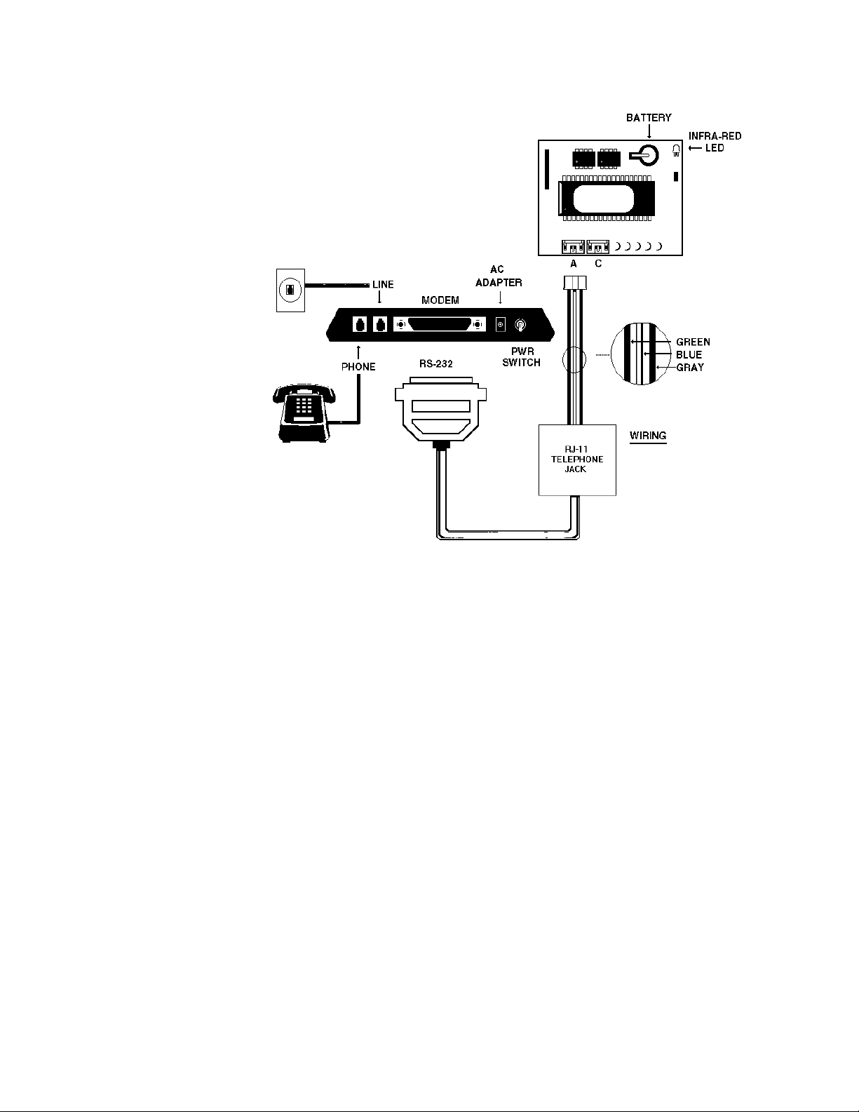
The HUB
PLUS
system
can be accessed from a
remote site. This enables
you to manipulate any of
the data in the system as if
you were on the site with
your personal computer,
via modem. This will
require two IEI modem
kits, model #SS-MODEM-
144. One is to be located
at the jobsite, with the
HUB controllers, and the
other modem kit is to be
located at the remote site,
with the computer. You will
also need one IEI 3.0 version P.C. Software kit
model #PCSFTWR. Both
the remote location with
the computer , and the job
site, with the HUB controllers, need to have phone lines available to work.
SECURITY
CHIP
21
Remote Access From A Modem
Modem Wiring And Programming At Job Site
Diagram A.
Page 22

3. Once the security chip is installed, you must program each hub with a door number. If you do not do
this, the software will not be able to locate the HUB controllers, and the software will not show the doors
as being on-line. Program each HUB as follows:
• Place HUB control in program mode by pressing 99 # (master code) *, at HUB keypad.
• Verify HUB is in program mode, yellow light should be flashing slowly.
• Press 43 # 0 # (door number in two digits) # * *
• Press * to exit program mode, yellow light will stop flashing.
• Do these programming steps to assign door numbers to all the HUBs in the system.
• Make sure that each HUB has a different door number.
• The HUB control that is to be assigned “door one” must
be the one with the security
chip and physically located first in the network. This is the HUB that you will now hookup to the modem.
4. To hook-up the modem at the job site, use the diagram on page 21.
Connect the three conductor harness with the green, blue, and gray wire to the RJ-11 telephone jack as
shown in the diagram on page 21. Connect the three conductor cable to port “A” of HUB controller #1.
Connect the the telephone cable (included) to the RJ-11 telephone jack. Connect the other end of the telephone cable to the RS-232 jack. Connect the RS-232 jack to the modem. Connect telephone into jack
marked “phone”, and connect outside line into jack marked “line”. NOTE: You will find that a cable in the
modem kit will not be used at the job site.
5. HUB #1 must be programmed with two commands that will enable and setup the unit to communicate
with the modem.
• Place HUB control #1 in program mode by pressing 99 # (master code) *, at HUB key
pad.
• Verify HUB is in program mode, yellow light should be flashing slowly.
• Press 31 # 8 # 1 # ** remote access enabled
• Press 35 # 1 # 0 # ** select modem string
• Press * to exit program mode
6. At HUB #1 run self test, this will setup a communication link hub #1 and modem. This is NOT
done
with the HUB in program mode.
• Press 7 8 9 0 # 1 2 3 4 5 6 *
The self test command will run a simple diagnostics test. This checks the communication between the
two circuit boards of the HUB, it will also test the keypad as well. On the HUB, you should see the lights
cycling between the different colors and ending with the sounder beeping.
22
Page 23

Secured Series Hub Control w/ Modem
Off-site/Remote Location Configuration
DB-9
DB-25
To Comm. Port.
Use
DB-25 or DB-9
Connector
At the remote site, you will need the second modem kit. You will also need the diskette from the P.C.
Software Kit, one of the two RJ-11 phone jacks, one of the two straight cords, and the two connectors.
Both the 25 pin and the 9 pin connector are labeled “ to P.C.”.
To setup the computer, follow the instructions with the P.C. Software on how to guide you thru the
Comm. Port Test. This will require you to plug-in the DB-25 or the DB-9 connector into either communication port one or two, located in the back of the computer. Then plug the telephone cable into the RJ-11
jack, and proceed to the Comm. Port test.
Once the test is complete, follow diagram above to complete hook-up.
23
Remote Site Wiring To P.C.
Page 24

PROGRAMMING FROM THE HUB
Each secured series HUB control module, with a reader, represents a stand alone system, and can be
programmed at the HUB controller. This programming guide had been broken up into boxes in order to
allow you the opportunity to find the section that pertains to your application. This section is for programming on the HUB’s keypad, located at the front of the HUB control unit.
Much of the programming had been covered and explained in the section pertaining to that specific
feature. Programming with the IEI software is covered in a different instruction that is provided with the IEI
software kit.
The first step in programming is always to place the HUB into program mode. When the HUB is in program mode, the yellow light will be flashing at a slow rate. When the yellow light stops flashing the HUB is
no longer in program mode. If the programming is not taken or not entered correctly, the yellow light stays
on solid, indicating to you to re-try the process. If the HUB will not go into program mode refer to the troubleshooting guide.
In order to place the HUB into programming mode you need to know the master code. The master
code is the code that is stored in register one. To place the HUB into programming mode press 99 # and
the master code followed by the * button, now the yellow light should be flashing. The factory default code
is 1234*. This code is also referred to as user one.
The master code should not be programmed as a card, or touch chip, because that will keep you from
using “user one” for programming since you cannot program from the front ends. The master code also
sets the door open time for all the other users, and the request to exit time. The master code cannot be
set for a latched output.
Each code programmed may consist of a different quantity of digits. A code may consist of only two
digits, or up to six digits in length. If you try to put a code into memory that had been previously entered
into a different register the yellow light will stop flashing and stay solid, indicating the action was impossible
to accomplish. Try a different code. Repeating digits in the same code is acceptable.
Changing the main relay time will allow users the proper amount of time to get from the front end to the
door before the main relay re-locks the door. Setting the main relay time for the master code, or user one,
will simultaneously set the time for users in register two thru register five hundred. The factory default relay
time is five seconds. To change this or the codes follow the steps listed below.
CHANGE MAIN RELAY TIME
Time can be set in one second increments from one second to ninety seconds, all other users will follow this time with only one exception, latching users, covered next.
• Press 99# master code *, yellow light flashing indicating HUB is in program mode.
• Enter in new time in seconds followed by #, next press 1#, representing user one, then the master
code *, you should see the yellow light flashing fast, verify code by pressing the master code in a
second time followed by a *, yellow light should now be flashing slow.
• Press * to exit programming.
24
Page 25

ADDING NEW OR CHANGING EXISTING CODES/CARDS/TOUCH CHIPS
• Enter program mode at the HUB, press 99# master code *, the yellow light should be flashing
slowly. 1234* is the factory set master code.
• Press the register number that represents the user to be added, or changed. Follow with a #
key. 2, would be user two, 500, would be user five hundred.
• CODE: Now press the two to six digit code and *, the yellow light should be flashing fast indi-
cating to you to verify the new code by pressing the same code and * a second time. The yellow light will
be flashing slow if the code is accepted.
• CARD/ T
OUCH CHIP: Press ** and go to reader and swipe card, or Press * if you wish to exit
program mode or continue to add or change codes.
SEQUENTIALLY ADDING CARDS/TOUCH CHIPS
If you are going to add several cards or touch chips into memory you will want to batch load them.
Sequentially adding IEI MAG stripe cards, and proximity cards are easy to keep in order because the code
is written on the front of each card. The touch chips are not in any order when received, so care should be
taken to print the user log before handing out the chips. This gives you the opportunity to log which chip
was given to which person.
To program several users from the front end, follow the program instructions below :
• Enter program mode at HUB by pressing 99 # master code *, yellow light should be flashing slow
• Press 53 # 1 # starting user number # ** at HUB, the starting user number is never 1, that is the
master code.
• Swipe first card/touch chip. On the card reader the red light should flash green indicating the card
was accepted. On the touch chip reader the sounder should beep indicating it was accepted.
• Continue to enter users or Press * to exit program at HUB
PROGRAMMING CARD READER KEYPAD
The CR/KP 500w (card reader keypad) can be programmed to accept code only users, card only
users, or combination code and card users. The users cannot share codes, or cards when programming for
card/code users. When a combination code/card user uses the device they may swipe the magnetic card
first, or press in the code first.
Once a code/card user has either swiped the card or pressed in the code they should see the yellow
light on the reader come on solid, indicating that the HUB is looking for the second half of the transaction
before granting access. Once access is granted the red light should turn green and the door should
release. To program this front end for card and code follow the programming instructions below.
• Enter program mode at HUB by pressing 99 # master code *, the yellow light should be flashing
slow.
• Press at the HUB 52 # 1 # user number # new code * new code * and then go to reader and
swipe the card. The red light should flash to green and back to red three times at reader indicating
the transaction is complete.
• Repeat the last step for each card/code user to be entered, their are no provisions made for
entering a batch of users in this style of device.
• Press * to exit program mode
To enter just a code, or just a card follow the programming steps described in the section titled “ADDING OR CHANGING
CODES OR CARDS”
25
Page 26

PROGRAMMING A USER TO LATCH THE MAIN RELAY
A latching code, card, or touch chip, may be programmed allowing a user the ability to bypass
the door for an indefinite amount of time. When the user then enters that code, card, or touch chip, the
HUB latches the relay on. Using any latching code, card, or touch chip a second time (either at the HUB or
the front end), and the relay latches to the opposite position.
When a user that is programmed to latch resets the main relay, the timed, or toggle users can then
resume standard operation. When a user latches the main relay on/off the event is stored in the transaction
log. The record will show “TGL ON” “TGL OFF”, also the time, date, door number, and user. To program a
user as a latching, or toggled output, follow the programming steps listed below.
• Enter program mode at the HUB by pressing 99 # master code *, the yellow light should be flash
ing slow.
• FOR A CODE, at HUB enter the time as 00 # user number # code * code *
• FOR
A CARD, OR TOUCH CHIP, at HUB enter the time as 00 # user number # **, and swipe card
or touch chip at reader.
• FOR
A CARD READER KEYPAD, at HUB enter the time as 00 # user number # code * code *, then
go to reader and swipe card.
• Press * at HUB to exit program mode.
T
O DELETE USERS
In order to delete a user from the system the register that the user information is stored in must be
known. If you dump the user list in accordance with the instructions on page 18, you can find this information and continue with the programming steps. If the system is not equipped with the means to print this
list, then the programmer should have filled out a chart as to the location, or register, the users are located
in. To delete a user follow the programming instructions below.
• Enter the program mode at the HUB by pressing 99 # master code *, the yellow light should be
flashing slow
• Press the user number and # **Press * at HUB to exit program mode.
PROGRAMMING A DURESS CODE
When utilized, a user may press the # key within three seconds of a valid code activating the duress
feature. Programming this option will enable any code programmed into a specific HUB to activate a
relay output. This can be used to activate a silent alarm during a hold up, or hostage style situation. This
feature is not available with card readers or touch readers. The output will activate the propped door relay
for five seconds.
When programmed for duress, the door ajar output will be disabled at that HUB. To wire output use
diagram “A” on page 7. Connect propped door relay to an auto-dialer. Duress is added to the transaction
log when enabled, and the “door closed” subtracted from the transaction log. Duress will not operate if a
Relock code is entered prior to the # key. To program this feature follow the instructions below.
• Enter programming mode at HUB by pressing 99 # master code *, yellow light should be flashing
slow
• Press 31 # 9 # 1 # **, to activate
• Press 31 # 9 # 0 # **, to disable
• Press * to exit program mode
26
Page 27

KEYPRESS FEEDBACK
Keypress feedback is a feature used to enable a sounder to beep once on each key press at HUB keypad, KP-500r, KP-500wp, KP-500i, or KP-500w. The output is factory set “on”, and helps the user to determine if the digit was pressed hard enough to be acknowledged. To enable/disable this feature, follow the
programming steps below.
• Enter program mode at HUB by pressing 99 # master code *, yellow light should be flashing slow
• Press 30 # 0 # 1 # ** to enable
• Press 30 # 0 # 0 # ** to disable
• Press * to exit program mode
RESET MASTER CODE AND SYSTEM DEFAULTS
Programming this command at the HUB will not erase the user data stored in registers two thru five
hundred. This can be useful if the HUB has a glitch in the program and is not running correctly, or if you
simply wish to reset system defaults in order to understand what has been programmed earlier. To program
this command follow the program steps below.
• Enter program mode at HUB by pressing 99 # master code *, the yellow light should now be flashing
slow
• Press 46 # 0 # 0 # **
• Press * to exit program mode
ERASE ENTIRE KEYPAD MEMORY AND RESET FACTORY DEFAULT
Programming this command will erase the entire HUB memory including any user information. This
would be used if the programmer needed to erase a specific user and could not retrieve the user log. To
program this command follow the program steps below.
• Enter program mode at HUB by pressing 99 # master code *, the yellow light should be flashing
slow
• Press 46 # 00000 # 00000 # **
• Press * to exit program mode
AUT
O-UNLOCK AUTO- RELOCK TIME ZONES
The HUB control module is capable of being programmed with up to eight time zones. A time zone is a
window that you can issue to a specific user that would limit the hours access would be granted. This is
possible because each HUB control is equipped with a twenty four hour clock, keeping track of the time of
day. The HUB is also capable of telling what day it is and the date. An “auto - unlock” time zone is a variation of a standard time zone. This type of time zone will unlock the door when programmed to do so, and
re-lock again after the time zone ends. The eight time zones per HUB can be assigned to be Auto - Unlock
time zones thru programming.
27
Page 28

The HUB control is factory programmed with time zone eight assigned as “auto - unlock” , open at
0900, re-lock at 1700, Monday through Friday. In order to change the time, days, or exclude holidays the
P.C. software will be required. If the HUB is pre-programmed prior to installation, or the P.C. is unavailable,
auto - unlock can still be re-assigned to existing pre-programmed zones, or turned off the time zones from
the front of the HUB.
When the HUB activates the auto - unlock time zone, the green light on the HUB and front end will flicker off and back on. Every 900 milliseconds the green light will turn off for 100 milliseconds . This will help
the users distinguish between a toggled/latched door (solid green), and the auto - unlock time zone being
active.
“First in auto - unlock”
is a command that programs the HUB to hold the door locked until someone is
granted access during that auto - unlock zone. This means that the door will not unlock automatically at the
set time but rather hold the door locked until the next access is granted during that specific window.
RELOCK CODE can be programmed in order to give the operator the ability to clear a toggled relay,
and will also re-lock an active auto - unlock situation. If the relock code is used to relock an auto - unlocked
door, the unlock feature will activate the next time the window opens. This feature is entered into the transaction log when used. The relock code will not allow access.
PROGRAMMING TIME ZONE FEA
TURES
• Press 99 # master code * to enter program mode at HUB
• Press 31 # 05 # 1 # ** Auto -unlock enabled
• Press 31 # 05 # 0 # ** Auto - unlock disabled
• Press 31 # 04 # 1 # ** Time zone enabled
• Press 31 # 04 # 0 # ** Time zone disabled
• Press 31 # 07 # 1 # ** First in auto - unlock enabled
• Press 31 # 07 # 0 # ** First in auto - unlock disabled
• Press 33 # time zone (1 to 8) # 1 # ** Auto- unlock time zone turned on
• Press 33 # time zone (1 to 8) # 0 # ** Auto - unlock time zone turned off
• Press 50 # 3 # user number # ** Assign RELOCK code active.
28
Page 29

TROUBLESHOOTING GUIDE
Red light turns green when access is accepted, but door does not open.
Check power supply voltage and verify the correct position of the P5 jumper.
While monitoring voltage at HUB V+ and V- terminal with meter, enter a valid code and insure
that voltage remains constant while locking device attempts to unlock and relock. If the voltage
varies 1/4 volt or more during this test, this is a problem and must be corrected. There are several
things to look for.
If you press 99 # (master code) * and the HUB does not go into program mode, it is possible
that the master code you are trying was changed or is not the master code. To get the HUB into program mode press SW1 momentarily. Do this with the power on. This micro switch is located on the
relay board next to the V+ terminal of TS1. If you need to pull the two circuit boards out of the plastic housing care must be taken. Handle the boards by the edges, the solder points can be shorted
together by fingers causing damage.
The yellow light should now be flashing slow, indicating that the HUB is in programming mode.
To program a new master code press 1# new code * new code *, the code can be one to six digits
and repeated numbers are ok. Press * to drop out of programming.
1. Verify that the power supply is rated sufficiently for all the equipment being powered.
2. Verify that the locking device, if on the same power supply , is set up for the voltage being
used. Example: If a lock draws 300ma at 24VDC, the same lock may draw 600ma at 12VDC,
especially if the unit requires that jumpers be placed in a different configuration. Place meter
across the lock power wires at lock and ensure lock is receiving the proper voltage.
3. If the resistor and M.O.V. have been installed, verify that the resistor value is correct according to specs : 10 ohms at 12VAC and 100 ohms at 24VAC.
Hub not entering program mode
The following problems will occur when the data lines of the four-conductor harness
(black/white and black/yellow) are reversed:
FRONT END
SYMPTOM
KP500R HUB: Red LED on
Front End: No Response
Keypress feedback still operates via sonalert
CR/KP500W HUB: Red LED on
Front End: No Response
Keypress feedback still operates via sonalert
Swipe good magcard: HUB: No change
Front End: Green LED flashes
29
Page 30

Swipe bad magcard: HUB: No change
Front End: Red LED flashes
CR500W HUB: Red LED on
Front End: No Response
Swipe good magcard: HUB: No change
Front End: Green LED flashes
Swipe bad magcard: HUB: No change
Front End: Red LED flashes
KP500I HUB: Red LED on
Front End: No Response
Keypress feedback still operates via sonalert, but not with yellow LED
KP500M HUB: Red LED on
Front End: No Response
Keypress feedback still operates via YELLOW led
TCH500W HUB: Red LED on
Front End: No Response
PRX500W HUB: Red LED on
Front End: Sonalert beeps twice
Good proxcard is swiped: HUB: No change
Front End: LED blinks from green to red
The following problems will occur when the power lines of the four-conductor harness (black and
red) are reversed:
FRONT END
SYMPTOM
All Front Ends HUB: Operates
Front End: No response
30
Page 31

PROGRAMMING OPTIONS CHART
If the pre-programmed default values must be changed or additional functions are desired,
the following options may be programmed once you have entered the programming mode.
To enter programming mode Press 99 # (master code) *yellow LED flashes slowly
1. Change master code/set main relay time Press (time) # 1 # (new code) *(new code)
*
Code only operation Note 10
Example: Master code of 4321/relay time of 10 seconds Press 10 # 1 # 4321 * 4321 *
2. Add/change user: code only Press (user number) # (new code) *(new code)
*
3. Add/change user: mag or prox card only Press (user number) # **(Swipe mag or proximity card)
4. Add/change user: code and magnetic card Press (user number) # (new code) *(new code) *(Swipe magnetic
card)
5. Add/change user to toggle main relay: code onl y Press (00) # (user number) # (new code) *(new code) *
6. Add/change user to toggle main relay: card onl y Press (00) # (user number) # **(Swipe mag or proximity card)
7. Add/change user to toggle main relay: Press (00) # (user number) # (new code)
*
magnetic card and code (new code) * (Swipe magnetic card)
8. Delete users Press (user number) #
**
9. Set Hub to send data Press 20 # FFF # LLL # **(refer to p age 12)
10 . Copy all Hub dat a to another Hub Press 21 # 0 # 0 #
**
(refer to p age 12)
11 . Print a list of user codes/cards Press 25 # 0 # 0 # **(refer to p age 17)
12 . Set Hub to receive dat a Press 29 # 0 # 0 #
**
(refer to p age12 )
13 . Set/Clear S tandared Option (0-2) Press 30 # option # s/c # * *
14 . Set/Clear System Option (0-11) Press 31 # option # s/c # * *
15 . Set printer output to InfraRed (IR) Port Press 31 # 3 # 0 #
**
(refer to Printing section p age 15)
16 . Set printer output to RS-232 Port A Press 31 # 3 # 1 #
**
(refer to Printing section p age 15)
17. To enable the auto unlock/lock time zone Press 31 # 5 # 1 #
**
18. To disable the auto unlock/lock time zone Press 31 # 5 # 0 #
**
19. To prevent access denied from being printed Press 31 # 6 # 0 #
**
20. To allow access denied to be printed Press 31 # 6 # 1 #
**
21 . Set time registers in real time clock Press 41 # HHMM # 0 #
**
(refer to Printing section p age 15)
22 . Set date registers in real time clock Press 4 2 # MMDDYY # Day of Week #
**
(refer to p age15)
23 . Set door number Press 43 # 0 # NN #
**
(refer to Printing section p age 15)
24. Set propped door tim e Press 44 # (time) # 0 #
**
25. Set forced door relay tim e Press 45 # (time) # 0 #
**
26. Reset master code and system default s Press 46 # 0 # 0 #
**
27. Erase entire keypad memory/reset default s Press 46 # 00000 # 00000 #
**
28. Assign dump code Press 50 # 2 # (user number) # code *code
*
29 . Assign dump card Press 50 # 2 # (user number) # **(Swipe mag or proximity card)
30. Add user for magnetic card or code operation Press 52 # 1 # (user number) # code *code
*
(Swipe magnetic card)
31. Sequentially add users: card onl y Press 53 # 1 # (st arting user number) # **(Swipe first mag or
3 2 . Print audit trail transaction log Press 70 # 0 # 0 #
**
(refer to Printing section p age 18)
33. Se t /Clear Event Logging Press 73 # event # s/c * *
34 . Delete audit trail transaction log Press 76 # 00000 # 00000 #
**
(refer to Printing section pg. 18)
Command 30 - Standard Options ( 30 # option # 0/1 # * * )
00 - keypress feedback (0= of f, 1=on)
01 - heavy duty mode (unused)
02 - auto entry (unused)
Command 31 - Standard Options ( 31 # option # 0/1 # * * )
00 - Vestibule/Door Ajar Output (not supported) 09 - Duress Select (1=enabled)
01 - V estibule/Forced Door Output (not supported) 10 - Print Live Select (1=enabled)
02 - V estibule Even On Read Error (not supported) 1 1 - Log Almost Full W arning (1=enabled
03 - Dump Device (0=IR, 1=RS-232)
04 - T ime Zones select (1=enabled)
05 - Auto Unlock select (1=enabled)
06 - Log Acces Denied (0=not logged, 1=logged
07 - 1st IN Auto-Unlock (1=enabled)
08 - Remote Access (1=enabled)
31
Page 32

Secured Series Access Control Parts and Accessories
SS- HC500 Hub Control Module
SS-HC500P Hub Plus Control Module (Modem, Live Print)
SS-MODEM-144 14.400 BPS Modem for use with the Secured
Series Hub Plus
Front End S
tyles
SS-KP500i
SS-KP500W
SS-KP500WP
SS-KP500R-BK
SS-KP500WM-BZ
SS-KP500WM-AL
SS-CR500W
SS-KPCR500W
SS-PRX500W-WH
SS-PRX500W-BK
SS-PRX500WM-BK
SS-TCH500W
Indoor Keypad
Weather Resistant Keypad
Weatherproof Keypad
Ruggedized/Weatherproof Keypad (Black)
Mullion Keypad (Bronze)
Mullion Keypad (Satin Aluminum)
Card Reader (Weatherproof)
Keypad/Card Reader (Weatherproof)
Proximity Card Reader (Single gang) White
Proximity Card Reader (Single gang) Black
Proximity Card Reader (Mullion) Black
Touch Reader (Chip Reader) Weatherproof
Cards / Chips ( Select for appropriate front end)
Magnetic Striped Cards
Magnetic Striped Cards
Magnetic Striped Cards
Proximity Cards
Proximity Cards
Proximity Cards
Touch Reader Chips
Touch Reader Chips
Touch Reader Chips
(10 per pack)
(25 per pack)
(100 per pack)
(10 per pack)
(25 per pack)
(100 per pack)
(10 per pack)
(25 per pack)
(100 per pack)
SS-MagCrd-10
SS-MagCrd-25
SS-MagCrd-100
SS-PrxCrd-10
SS-PrxCrd-25
SS-PrxCrd-100
SS-TchChp-10
SS-TchChp-25
SS-TchChp-100
SS-PrintCon Printer Connection Kit
SS-IRPRINT Wireless Printer
SS-PCSFTWR Software (DOS Based) Allows hook-up of RS232 network from Hub
Control Modules
SS-LRPSFTWR Transaction Log Retrieval Software (DOS Based)
PWR/TMPR-12 IEI 1 amp 12VDC Power Supply (Board Only) Provides filtered and
regulated 12 volt power. Switch selectable AC/DC.
Built-in suppression for locking devices
PSW/ENC-12V IEI 1 amp 12VDC Power Supply In Enclosure (Hub mounts to face)
R-Lighting Ruggedized Lighting Kit for use with all Ruggedized keypads
IEI-289 Tamperproof Screws (Tri-Head) for KP500i and KP500w (10 pcs.)
IEI-270 Tamperproof Socket (1/4” Drive) for 289 Tamper Screws
IEI-288 Tamperproof Screws. Allen with pin (20 pcs.)
IEI-271 Tamper Wrench for Allen with pin (1/4” Drive)
32
Page 33

Product Specification
ELECTRICAL
Volt age Requirement s:
Hub Control with Proximity Reader 12VDC
Hub Control with any other Front End 12 to 24 volt s AC or DC (selected by jumper)
W iring Requirement s:
Maximum Distances with shielded : 18 A WG 20 A W G 2 2 A W G
Hub Control to Front End 1000 500 250
Hub Control to Hub Control 1000 500 250
Hub Control to Printer or PC 1000 500 250
Current Draw:
Hub Control only @12VDC 21 ma typical- 51 ma maximum
@24VDC 24 ma typical- 57 ma maximum
Relays for Propped Door, Forced Door & Alarm Shunt require an additional 15 ma each.
Indoor, W eather Resist ant, Ruggedized, Weather Proof Keypads,
Magnetic Card Reader/Keypad and Touch Reader @12VDC 32 ma typical- 62 ma maximum
@24VDC 34 ma typical- 68 ma maximum
Magnetic Card Reader @12VDC 34 ma typical- 59 ma maximum
@24VDC 36 ma typical- 70 ma maximum
Mullion Keyp ad @12VDC 30 ma typical- 58 ma maximum
@24VDC 32 ma typical- 66 ma maximum
Proximity Reader @12VDC 75 ma typical- 107 ma maximum
Outputs:
RS-232 Ports for Printing and Networking Functions: 1200 baud rate, 8 dat a bit s, 1 stop bit, no p arity, min 120 CPS
printer
Infrared (IR) output of transaction buf fer to handheld printer
Main relay: SPDT 5 ampere @24 VDC
Forced Door, Propped Door, Alarm Shunt Relays: SPDT 1 ampere @24 VDC
MECHANICAL
Hub Control dimensions: 2.75 w x 4.50 h x 2.50"d
Indoor & Weather Resist ant Keyp ad dimensions: 2.75 w x 4.50 h x 1.00"d
W eather Proof Keypad dimensions: 3.00 w x 4.50 h x 1.55"d
Ruggedized Keypad dimensions: 3.75 w x 5.25 h x 2.50"d
Mullion Keyp ad dimensions: 1.75 w x 6.50 h x 1.00"d
Proximity Reader dimensions: 2.75 w x 4.50 h x 0.50"d
Touch Reader dimensions: 2.75 w x 4.50 h x 1.75"d
Mullion Proximity Reader dimensions: 1.75 w x 5.50 h x 0.75"d
Magnetic Card Reader dimensions: 1.75 w x 4.50 h x 1.55"d
Magnetic Card Reader/Keypad dimensions: 4.50 w x 4.50 h x 1.55"d
Magnetic Card Reader Head life expect ancy: 300,000 card swipes
ENVIRONMENT
AL
Temperature: -20 F to 130 F (-28 C to 54 C)
NOTE: CONTA CT THE FAC-
TO RY FOR FURTHER
WIRING SPECIFICATIONS
33
606-5033 Rev. 1.04Visit our website for Access Control & Glassbreak information,
New Products, Specifications, Applications, Seminars, and Partners
@ WWW.IEIB.COM
INTERNATIONAL ELECTRONICS, INC.
427 TURNPIKE STREET, CANT O N ,M A 02021 U.S.A.
800-343-9502, 617-821-5566
617-821-4443 (FAX)
FAX INFORMATION CENTER 617-821-0734 (FROM YOUR FAX MACHINE)
10/96
TM
INTERNATIONAL
ELECTRONICS, INC
Page 34

34
If this product does not seem to operate properly, please call our Technical Department toll free at 1-800-
343- 9502 (617-821-5566) Monday -Friday 8:00 am-7:00 pm EST.
We understand your time is valuble, and we know that calling our Technical Support Department will ensure
that you’ll make the most profit possible with your IEI product. Thank you for your purchase. We appreciate your
business.
International Electronics,Inc.(IEI) warrants its products to be free from defects in material and workmanship, when they
have been installed in accordance with the manufacturer’s instructions, and have not been modified or tampered with. IEI does
not assume any responsibility for damage or injury to person or property due to improper care, storage handling, abuse, misuse,
normal wear and tear, or an act of God.
IEI’s sole responsibility is limited to the repair (at IEI’s option) the replacement of the defective product or part when sent
to IEI’s facility (freight and insurance charges prepaid), after obtaining IEI’s Return Merchandise Authorization. IEI will not be
liable to the purchaser or any one else for incidental or consequential damages arising from any defect in, or malfunction of, it’s
products.
This warranty shall expire two years after shipping date for DOOR-GARD keypads. Except as stated above, IEI makes
no warranties, either express or implied, as to any matter whatsoever, including, without limitation to, the condition of its products,
their merchantability, or fitness for any particular purpose.
 Loading...