

Page 1
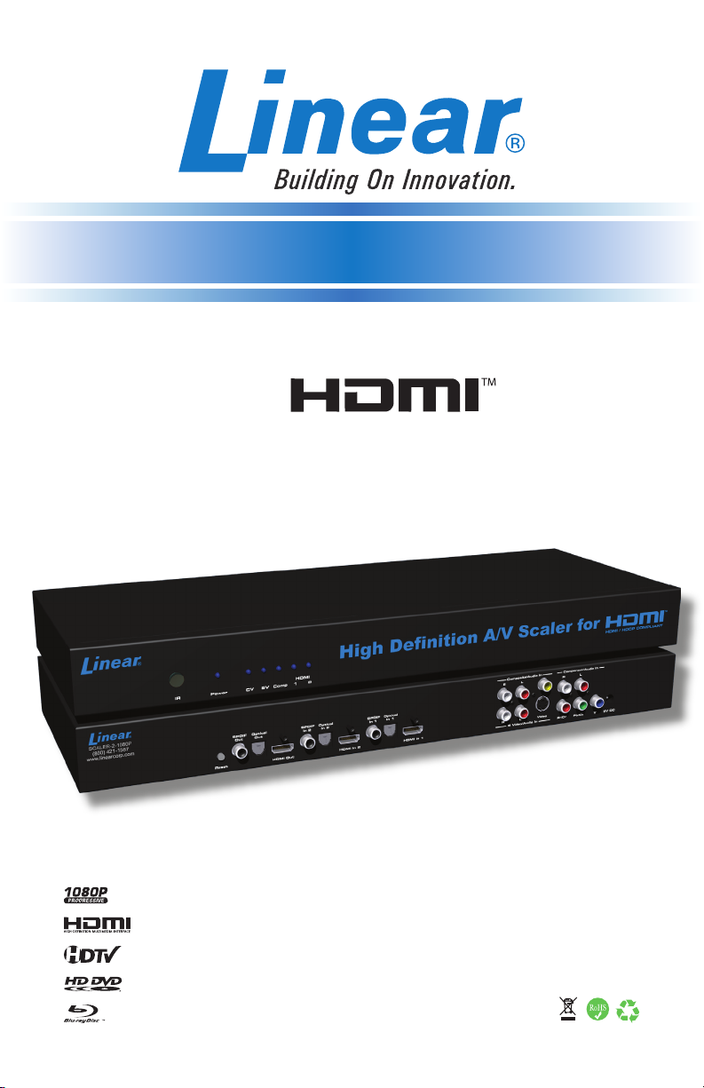
High Denition A/V Scaler
For
Model # SCALER-2-1080P
USER MANUAL
www.linearcorp.com
Page 2

Page 3

ASKING FOR ASSISTANCE
Technical Support:
Telephone (800) 421-1587
(760) 438-7000
Fax (760) 438-7199
Technical Support Hours:
6:30 AM - 4:30 PM PST Monday through Friday.
Email:
techsupport@linearcorp.com
Website:
www.linearcorp.com
Notice
Linear LLC reserves the right to make changes in the hardware, packaging
and any accompanying documentation without prior written notice.
© 2008 Linear LLC, All Rights Reserved
Page 4

TABLE OF CONTENTS
Introduction / Operation Notes1.
Features2.
Panel Descriptions3.
Connecting and Operating the 4. HIGH DEFINITION A/V SCALER FOR HDMI
RMT-SR-IR Remote Description5.
Hi6. gh Denition A/V Scaler For HDMI Conguration / Entering The Menu
System / Main Menu / Video
Hi7. gh Denition A/V Scaler For HDMI Conguration / Video Continued
Hi8. gh Denition A/V Scaler For HDMI Conguration / Output / Color
Hi9. gh Denition A/V Scaler For HDMI Conguration / Color Continued / OSD
Hi10. gh Denition A/V Scaler For HDMI Conguration / OSD Continued / Audio
Hi11. gh Denition A/V Scaler For HDMI Conguration / Information
RMT-SR-IR Installation12.
IR Code Conguration13.
Wiring Diagram14.
Specications15.
Warranty16.
Page 5

INTRODUCTION
The Linear High Denition A/V Scaler for HDMI allows you to upscale
and switch your standard denition or high denition Component and
HDMI sources to resolutions up to 1080p. Anything from set-top boxes,
DVD players to the next generation of gaming consoles can be plugged
into the Linear High Denition A/V Scaler for HDMI.
The Linear High Denition A/V Scaler for HDMI supports one Component
source with analog audio, one Composite or S-Video source with analog
audio, and two HDMI sources with digital audio. The analog audio from
the analog sources is digitized and outputted to the HDMI connection as
well as the digital audio outs. The HDMI inputs also have separate digital
audio inputs, so you can use DVI sources and separate digital audio and
the High Denition A/V Scaler for HDMI will embed the digital audio into
the HDMI output as well as the digital audio outs.
How It Works
You simply connect all your components and your display. Easy to use
on-screen menus are accessible through the IR remote control. The
IR remote control allows for effortless setup and image adjustment to
accommodate different viewing modes and screen sizes to perfect your
nal picture.
OPERATION NOTES
READ THESE NOTES BEFORE INSTALLING
OR OPERATING THE HIGH DEFINITION A/V SCALER FOR HDMI
When initially powering on HDMI sources, it is important to have the High •
Denition A/V Scaler for HDMI’s output selected to that source to ensure that
the EDID is relayed properly.
Compatible with all HDMI and DVI* displays•
The Scaler to 1080P has a 15-foot limit on how far it can transmit the DDC •
(Display Data Channel) information out of the HDMI output jack to the display.
Connections to displays at distances longer than 15 feet should use a true DDC
re-clocking solution such as our CAT-5 based HDMI signal extender device
(Linear part number HDMI-CAT5-EXT).
HDMI/HDCP compliant•
NOTE: *When used with a DVI to HDMI adapter
1
Page 6

FEATURES
Features
Both digital and analog inputs are format converted and pixel re-scaled •
through the Home Theater Scaler Plus. It outputs a large range of formats
and resolutions that will easily match the native resolution/format of your
display to ensure highest picture quality
DVI/HDCP/HDMI compliant input: Operates up to 165MHz (Up to UXGA •
@60Hz)
Supports digital HD output up to 1080p•
Integrated 8-bit triple-ADC/PLL•
Integrated DVI/HDCP/HDMI compliant receiver•
Dual high quality scaling engines•
Dual 3-D motion video adaptive de-interlacers with smooth low angle edge•
Automatic 3:2 pull-down & 2:2 pull-down detection and recovery •
High performance frame rate conversion engine •
The Proprietary Advanced Color Engine technology gives you brilliant and •
fresh color, intensied contrast and details, vivid skin tone, sharp edge,
accurate and independent color control
Option to select Audio input from HDMI or Optical/SPDIF audio source•
3D noise reduction on analog inputs only•
Operates through on-screen menu control and remote control •
Aspect Ratio Control •
Digital Audio Delay to match audio/video timing •
Less than one frame delay for gaming devices•
Includes:
(1) Scaler to 1080P
(1) 6 ft HDMI cable (M-M)
(1) 5V DC Power Supply
(1) RMT-SR-IR Remote control
(1) User’s Manual
2
Page 7
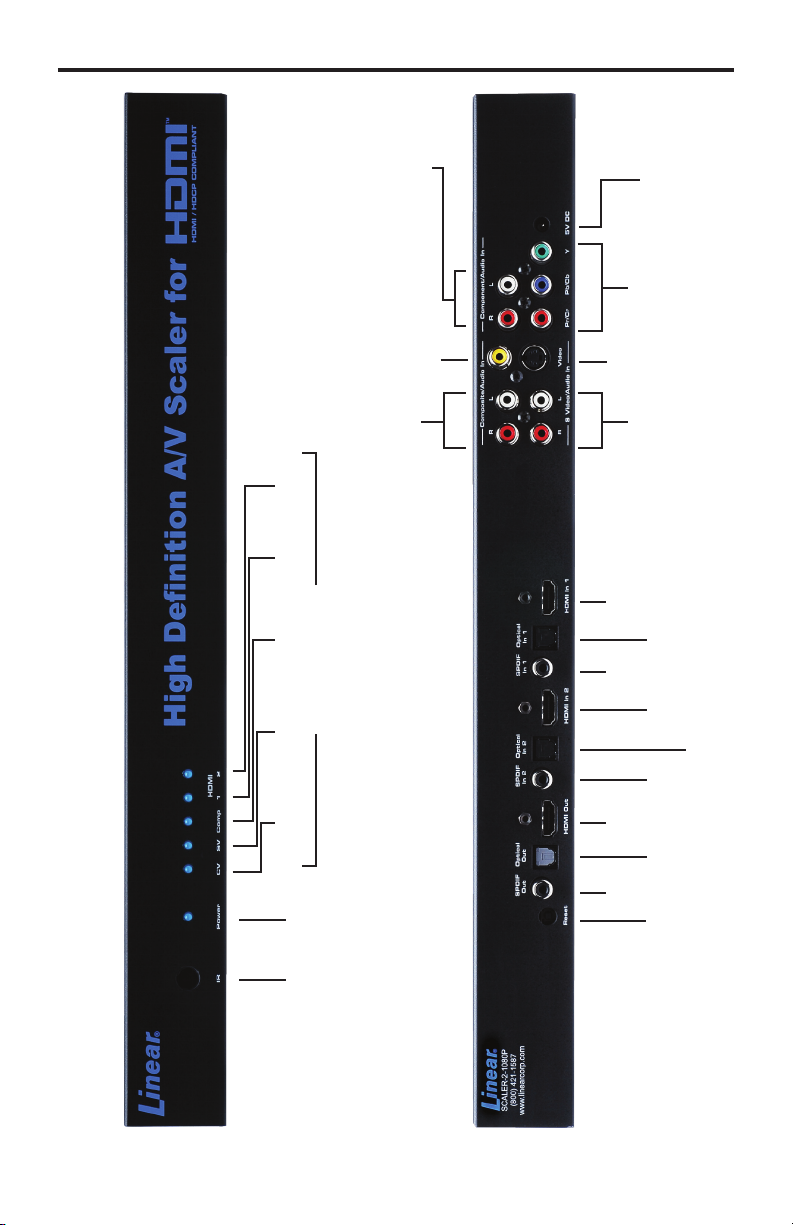
PANEL DESCRIPTIONS
Front Panel
HDMI 1 HDMI 2
LED INDICATORS
Input
Component Audio
Composite Video Input
Composite Audio Input
Back Panel
Input
5V DC
Input
Component
S-Video Input
S-Video Audio Input
HDMI
Input 1
Optical
SPDIF
Input 1
HDMI
Input 1
Input 2
Composite S-Video Component
LED
IR Eye Power
Input 2
Optical
SPDIF
Input 2
HDMI
Output
Output
Optical
SPDIF
Output
Reset
Button
3
Page 8

CONNECTING AND OPERATING THE
HIGH DEFINITION A/V SCALER FOR HDMI
How to Connect the High Denition A/V Scaler for HDMI
Connect the HDMI output on the 1. High Denition A/V Scaler for HDMI to the
display using the supplied HDMI cable.
Connect either the digital SPDIF or digital Optical audio output to the display or 2.
an external audio processor using user supplied digital audio cables.
Connect the sources to the 3. High Denition A/V Scaler for HDMI using user
supplied cables.
Connect up to two HDMI sources with optional digital SPDIF/Optical •
audio using HDMI cables and digital audio cables.
Connect one Component source with analog audio using a 3 RCA •
Component video cable and a 2 RCA analog audio cable.
Connect one S-Video source with analog audio using a S-Video cable •
and a 2 RCA analog audio cable.
Connect one Composite source with analog audio using a 1 RCA •
Composite video cable and a 2 RCA analog audio cable.
Plug the 5V DC power supply into the 4. High Denition A/V Scaler for HDMI.
Press the POWER button on the RMT-SR-IR remote to begin operation of 5.
the High Denition A/V Scaler for HDMI.
Power on the display.6.
Power on the source(s).7.
NOTE: When initially powering on HDMI sources, it is important to have the High
Denition A/V Scaler for HDMI’s output selected to that source to ensure that the
EDID is relayed properly.
OPERATING THE HIGH DEFINITION A/V SCALER FOR HDMI
The High Denition A/V Scaler for HDMI has a built in GUI for navigating the
various functions. The GUI is navigated by the included IR remote control.
Please see the RMT-SR-IR Remote Description on the next page for functional
information.
4
Page 9

RMT-SR-IR REMOTE DESCRIPTION
1
2
4
6
8
Output - Cycles through the available output resolutions. Please see the section 1.
HIGH DEFINITION A/V SCALER FOR HDMI CONFIGURATION / Output on
page 8 for the output resolution table.
Input - Cycles though all of input sources. The selectable inputs are 2.
Composite, S-Video, Component, HDMI 1, and HDMI 2.
Power - Turns the unit on and off (standby).3.
3
5
7
9
Exit - Exits the current menu option and menu system.4.
Menu - Displays the menu system for adjustment of options.5.
Navigation Keys - These include up, down, left, and right buttons for 6.
navigating the menu system.
The OK button will select specic menu options for adjustment and will also 7.
conrm/cycle-through selections (Output/Input).
Reset - Resets the input and output resolutions to factory default.8.
Auto Adjust - Sets the display for optimal resolution and aspect ratio based 9.
on the display’s EDID information and the currently selected sources output
resolution.
5
Page 10

HIGH DEFINITION A/V SCALER FOR HDMI CONFIGURATION
Entering the Menu System
Pressing the Menu button on the included RMT-SR-IR remote control will display the
GUI (graphical user interface) for adjustment options.
The GUI is overlaid onto the outgoing video to the display. Therefore, the selected
source must be outputting a compatible resolution for viewing on the display. If video
is not visible on the display, the GUI will also fail to be displayed. To correct this,
please follow the steps below.
Verify that the source is on and outputting a video signal.1.
Verify that the RMT-SR-IR remote channel is in the default position (page 13).2.
Verify that the 3. High Denition A/V Scaler for HDMI is selected to the chosen
source.
Press the Output button on the RMT-SR-IR remote control to cycle through 4.
output resolutions until video is displayed. Please see page 8 for a listing of the
available output resolutions and cycle order.
Navigation
Use the directional buttons to navigate the menu system. Press the OK button to
enter a sub category and also to select a menu item for adjustment. Use the Left and
Right buttons to adjust the selected menu item. Press the EXIT or OK button to return
to the previous menu. Use the LEFT and RIGHT buttons to adjust selected options.
Pressing the EXIT button while in the main menu will exit out of the menu system.
MAIN MENU
The following are the main menu options. Use the UP and DOWN buttons to choose
your desired subcategory and press OK to enter it.
VIDEO
COLOR
OUTPUT
OSD
AUDIO
INFORMATION
VIDEO
Picture Mode
Preset and user congurable settings for different viewing scenarios. Preset settings
will not allow user adjustment. Only the USER option will allow customized video
settings. The USER settings are saved.
Options:
Standard - useful for general content •
Movie - useful for dimly lit environments•
Vivid - useful for accentuating colors for a more vibrant image•
User - user congurable settings•
NOTE: User settings are saved. However, user settings for the digital inputs (HDMI
1 and 2) are linked and user settings for the analog inputs (Composite, S-Video, and
Component) are linked. i.e. adjustments to video user settings made on HDMI 1 will
be reected in HDMI 2.
6
Page 11

HIGH DEFINITION A/V SCALER FOR HDMI CONFIGURATION
VIDEO CONTINUED
Press OK to begin adjusting settings. Use the LEFT and RIGHT buttons to change
settings. Press the OK button once the desired settings are made.
Contrast
Adjusts the contrast in increments of 1 on a scale of 1 to 100 (default 50).
Brightness
Adjusts the brightness in increments of 1 on a scale of to 100 (default 50).
Hue
Adjusts the hue in increments of 1 on a scale of 1 to 100 (default 50).
Saturation
Adjusts the saturation in increments of 1 on a scale of 1 to 100 (default 50).
Sharpness
Adjusts the sharpness in increments of 1 on a scale of 1 to 100 (default 50).
Scale
Adjusts the aspect ratio of the video.
Options: Full, Overscan, Underscan, Letterbox Underscan, Pan Scan Underscan,
Letterbox Full, Pan Scan Full
4:3 Source
Example
16:9 Source
Example
Full - Stretches the image to ll the screen
Overscan - Stretches the image to fullscreen and just beyond the border of the display
Underscan - Stretches the image to fullscreen and just within the border of the screen
Letterbox Underscan - Stretches the image to 16:9 aspect ratio with underscan
Pan Scan Underscan - Stretches the image to 4:3 aspect ratio with underscan
Letterbox Full - Stretches the image to 16:9 aspect ratio without underscan
Pan Scan Full - Stretches the image to 4:3 aspect ratio without underscan
N.R. (Noise Reduction) - Only for Composite and S-Video Inputs
Reduces video noise inherent in analog video signals.
Options:
Off - default•
Low•
Middle •
High•
7
Page 12

HIGH DEFINITION A/V SCALER FOR HDMI CONFIGURATION
VIDEO CONTINUED
H-Pos (Horizontal Position)
Adjusts the image’s horizontal position on the screen.
Adjusts in increments of 1 on a scale of 1 to 100 (default is 50)•
V-Pos (Vertical Position)
Adjusts the image’s vertical position on the screen.
Adjusts in increments of 1 on a scale of 1 to 100 (default is 50)•
Y/C Separation - Only for Composite Input
Selects the method in which the brightness and color are separated from the
composite video signal.
Options:
Auto - automatically selects the optimal method (default)•
2D - Separation based on single frame analysis•
3D - Motion adaptive color separation based on multiple frame analysis•
Coring - Only for Composite Input
Adjusts the threshold level for pixel noise evaluation. This relates to how much of the
image is processed in regards to noise reduction.
Adjusts in increments of ~6.5 on a scale of 1 to 100. (default is 20)•
OUTPUT
This menu sets the output resolution for all video sources. Use the directional buttons
to choose your desired output resolution and press the OK button to set it. These
outputs can be cycled through in the numbered order below when not in the menu
system by pressing the OUTPUT button on the RMT-SR-IR remote control.
VGA 480i 576i WXGA
1 6 11 16
SVGA 480p 576p WSXGA
2 7 12 17
XGA 720p 60 720p 50 WUXGA
3 8 13 18
SXGA 1080i 60 1080i 50 Native
4 9 14
UXGA 1080p 60 1080p 50
5 10 15
Native
This option will select the native resolution of the connected display based on the
EDID from the display.
NOTE: If a resolution that is not supported by the display is selected, the menu GUI
will not longer be visible. To correct this, press the OUTPUT button on the RMT-SR-
IR remote control and cycle through the output resolutions until a supported mode is
displayed.
8
Page 13

HIGH DEFINITION A/V SCALER FOR HDMI CONFIGURATION
COLOR
Press OK to begin adjusting settings. Use the LEFT and RIGHT buttons to change
settings. Press the OK button once the desired settings are made.
Color Tone
Sets the color for the appearance of white. Only the USER option will allow
customized settings. The USER settings are saved.
Normal - Normal white color appearance (default)•
Warm - Slight red shift to white appearance•
Cool - Slight blue shift to white appearance•
User - User adjustments to Red, Green, and Blue•
Red
Adjust the red color in regards to the appearance of white for the USER setting.
Adjustments are in increments of 1 from 1 to 100 (default is 50)•
Green
Adjusts the green color in regards to the appearance of white for the USER setting.
Adjustments are in increments of 1 from 1 to 100 (default is 50)•
Blue
Adjusts the blue color in regards to the appearance of white for the USER setting.
Adjustments are in increments of 1 from 1 to 100 (default is 50)•
OSD (ON SCREEN DISPLAY)
Press OK to begin adjusting settings. Use the LEFT and RIGHT buttons to change
settings. Press the OK button once the desired settings are made.
H-Pos (Horizontal Position)
Adjusts the OSD’s horizontal position on the screen.
Adjustments are in increments of 1 from 1 to 100 (default is 50)•
V-Pos (Vertical Position)
Adjusts the OSD’s vertical position on the screen.
Adjustments are in increments of 1 from 1 to 100 (default is 50)•
Time Out
Adjusts the amount of idle time, in seconds, before the OSD is automatically exited.
Adjustments are in increments of 1 from 1 to 100 (default is 10)•
Background
Sets the transparency level of the OSD background.
Adjustments are in increments of ~12.5 on a scale of 1 to 100 (default is 50)•
9
Page 14

HIGH DEFINITION A/V SCALER FOR HDMI CONFIGURATION
OSD (ON SCREEN DISPLAY) CONTINUED
Remote Channel
Sets the remote channel for use with the RMT-SR-IR remote control. If the selected
channel in this menu and does not match the channel set in the RMT-SR-IR remote,
the unit will cease to respond to IR commands from the remote.
Selectable remote channel from 1 to 4 (default is 1)•
AUDIO
Press OK to begin adjusting settings. Use the LEFT and RIGHT buttons to change
settings. Press the OK button once the desired settings are made.
Source
Sets the audio source for current input.
Options for Composite:
L/R1 - Composite analog audio input (default)•
Options for S-Video:
L/R2 - S-Video analog audio input (default)•
Options for Component:
L/R3 - Component analog audio input (default)•
Options for HDMI 1:
HDMI1 - HDMI 1 internal audio (default)•
Optical1 - Optical input 1•
Coaxial1* - SPDIF input 1•
Options for HDMI 2:
HDMI2 - HDMI 2 internal audio (default)•
Optical2 - Optical input 2•
Coaxial2* - SPDIF input 2•
Delay
Sets the audio delay for lip syncing correction.
Off - No delay (default)•
40ms - 40 millisecond audio offset•
110ms - 110 millisecond audio offset•
150ms - 150 millisecond audio offset•
Sound
Select general audio output function
On - Use selected audio source (default)•
Mute - No sound output •
*Coaxial is also know as SPDIF
10
Page 15

HIGH DEFINITION A/V SCALER FOR HDMI CONFIGURATION
INFORMATION
This menu will allow the user to view general information. There are no congurable
options in this menu.
Source - Displays current source•
Input - Displays current input source resolution•
Output - Displays current output resolution•
Version - Displays current rmware revision•
11
Page 16

RMT-SR-IR INSTALLATION
Remove battery cover from the back of the RMT-SR-IR remote.1.
Verify that dip switches 1 & 2 are in the down (OFF) position. (See page 13)2.
Insert the battery, hold the battery so that you can see the positive side 3.
facing up. The side that is not marked must be facing down.
Test the RMT-SR-IR remote by pressing ONLY one button at a time. The 4.
indicator light on the remote will ash once each time you press a button.
WARNING:
Do not press multiple buttons simultaneously and do NOT press buttons rapidly.
These actions will cause the remote to reset and steps 1-4 will have to be
repeated.
Note: The RMT-SR-IR ships with two batteries. Only one battery is required for
operation, the other battery is complimentary.
12
The optional IR extender allows you to
relocate your HDMI Switcher and still retain IR
control. Linear part# IR-EXTENDER
Page 17

IR CODE CONFIGURATION
How to Resolve IR Code Conicts
In the event that IR commands from other remote controls conict with the
supplied RMT-SR-IR remote control, changing the remote channel will alleviate
this issue. The RMT-SR-IR remote control has DIP SWITCHES for conguring
the remote channel. The High Denition A/V Scaler for HDMI must match the
remote channel set in the RMT-SR-IR remote control. Please see page 10 for
instruction on how to congure the channel on the High Denition A/V Scaler for
HDMI. By default, both the High Denition A/V Scaler for HDMI and the RMT-SR-
IR remote control are set to Channel 1.
Remote
Remote Channel 1:
Default
Remote Channel 3:
1 2
1 2
Remote Channel 2:
1 2
Remote Channel 4:
1 2
13
Page 18

WIRING DIAGRAM
HDMI
Component
S-Video
Composite
Digital Audio
Analog Audio
14
Maximum analog audio and video cable length is 50 ft
Maximum HDMI cable length is 15 ft at 1080P resolution without the use of an HDMI-SB or HDMI-CAT5-EXT
Page 19

SPECIFICATIONS
Digital Video Amplier Bandwidth ............................................................ 165 MHz
Component Video Bandwidth .................................................................. 350 MHz
Input DDC Signal ......................................................................... 5 Volts p-p (TTL)
Input Video Signal .............................................................................. 1.2 Volts p-p
Single Link Range ................................................................... 1080p/1920 x 1200
Input/Output HDMI Connector .............................................. Type A 19 pin female
Analog Video In Connector 1.................................................... 3 RCA Component
Analog Video In Connector 2...................................................... 1 RCA Composite
Analog Video In Connector 3 ...................................................................1 S-Video
Digital Audio In Connector ................................................. 2 Optical and 2 SPDIF
Digital Audio Out Connector .............................................. 1 Optical and 1 SPDIF
Analog Audio In Connector ............................................................... 3:2 RCA R+L
Power Consumption ....................................................................... 20 Watts (max)
Dimensions .............................................................. 6.875”W x 2.125”H x 6.875”D
Shipping Weight ............................................................................................ 4 lbs.
15
Page 20

WARRANTY
Note: These products are designed to be installed and serviced by trained professional
installation companies.
Linear LLC warrants this product to be free from defects in material and workmanship. For the
term of the warranty, see the list of products below. The Warranty Expiration Date is reected by
a date code that is afxed to all of Linear’s products. This warranty extends only to wholesale
customers who buy direct from Linear or through Linear’s normal distribution channels. Linear
does not warrant this product to consumers. Consumers should inquire from their selling dealer
as to the nature of the dealer’s warranty. There are no obligations or liabilities on the part of
Linear LLC for consequential damages arising out of or in connection with use or performance
of this product or other indirect damages with respect to loss of property, revenue, or prot, or
cost of removal, installation or reinstallation. All implied warranties, including implied warranties
for merchantability and implied warranties for tness, are valid only until warranty expiration date
as labeled on the product. This Linear LLC Warranty is in lieu of all other warranties express or
implied. Some states and countries do not allow limitations or how long an implied warranty lasts
or the exclusion or limitation or incidental or consequential damages, so the above exclusions
may not apply. The Linear LLC warranty gives specic legal rights in addition to other rights,
which may exist and vary from state to state and country to country.
All products returned for warranty service require a Return Product Authorization Number (RPA#).
Contact Linear Technical Services at 1-800-421-1587 for an RPA# and other important details.
Consumers: If you have trouble locating your installing company, please contact Linear LLC at
1-800-421-1587 and we will assist you with locating a service and Installation Company.
The following warranty period applies to this set of Linear branded products.
Linear High Denition Video products — Two (2) years. There is no warranty offered on the 1.
batteries supplied with the IR remote Control.
The warranty is limited to repair or replacement of products returned, freight prepaid, to
Linear LLC. There is NO PROVISION FOR LABOR COST OR OTHER REIMBURSEMENTS
OF ANY KIND.
Failures due to product abuse, negligence, improper installation, improper use, and 1.
electrical surge including damage from lightning, water damage or other damage due to
natural disasters are not covered by the warranty.
The warranty shall also be voided by any tampering with the date code, labels or other 2.
markings on the product.
Products that are damaged in transit to Linear LLC due to improper packaging or by the 3.
carrier (shipping company) will not be covered under the warranty. If the product was
damaged or lost by the carrier, it is the sender’s responsibility to create a claim against the
carrier.
The user is responsible for all labor costs associated with removing, reinstalling and 4.
returning the product to Linear LLC.
Linear LLC, at its option, will repair or replace the defective product.5.
Replacements will be made from B-Stock. If an exact replacement is not available Linear 6.
LLC, at its option will select the nearest equivalent product. The user is responsible for
freight charges to Linear LLC.
Linear LLC will return warranted repaired or replacements by UPS Ground or an equivalent 7.
service. A customer may pay the additional costs for second day or next-day service.
16
Page 21

Page 22

Page 23

Page 24

SCALER-2-1080P
(760) 438-7000
(800) 421-1587 FAX (800) 468-1340
www.linearcorp.com
Rev A
 Loading...