

Page 1
SUPERVISED WIRELESS
SECURITY CONSOLE
SECURITY
Installation & Programming Instructions
(760) 438-7000 • FAX (760) 438- 7043
www.linearcorp.com
Page 2
INTRODUCTION
CONGRATULATIONS for selecting Linear’s DVS-2400
Security System. The DVS-2400 Console incorporates many
advanced and sophisticated features. The system can be
expanded and customized to fit the installation’s specific needs.
The DVS-2400 Console and its accessories are designed and
manufactured by the oldest wireless security company in North
America. You can look ahead to many years of reliable service
with this Console and its accessories.
Many insurance companies offer discounts on homeowners
and renters policies when a security system is installed.
Discount credits vary with different companies and generally
increase in savings with an increase in the level of protection.
Inform the user to ask their insurance agent about savings
available.
NOTE: Some cities and municipalities may require an alarm
system permit. Check with your local authorities before
installing this system.
In this manual, the bullets preceding the text help to define the
step. For example:
This symbol indicates a feature.
◆
This symbol indicates an action to perform and
provides a box to check when the action is
completed.
This symbol is for lit indications or system
❇
sounds.
This symbol is for important notes.
✍
Page 3

TABLE OF CONTENTS
1. THE DVS-2400 SECURITY SYSTEM
CONSOLE . . . . . . . . . . . . . . . . . . . . . . . . . . . . . . . . . . . . . . . 2
DOOR/WINDOW SENSORS . . . . . . . . . . . . . . . . . . . . . . . . . . . . . 3
WIRELESS KEYPAD . . . . . . . . . . . . . . . . . . . . . . . . . . . . . . . . . 3
SMOKE DETECTORS . . . . . . . . . . . . . . . . . . . . . . . . . . . . . . . . . 3
REMOTE CONTROLS . . . . . . . . . . . . . . . . . . . . . . . . . . . . . . . . . 3
PANIC BUTTONS . . . . . . . . . . . . . . . . . . . . . . . . . . . . . . . . . . . 3
BILL TRAP . . . . . . . . . . . . . . . . . . . . . . . . . . . . . . . . . . . . . . . 3
PASSIVE INFRARED MOTION DETECTOR . . . . . . . . . . . . . . . . . . . . . 3
GLASS BREAK DETECTOR . . . . . . . . . . . . . . . . . . . . . . . . . . . . . 3
2. SECURITY SYSTEM FLOOR PLAN
EXAMPLE SYSTEM . . . . . . . . . . . . . . . . . . . . . . . . . . . . . . . . . . 4
DESIGN THE INSTALLATION . . . . . . . . . . . . . . . . . . . . . . . . . . . . . 4
3. TYPICAL SYSTEM SENSORS
DOOR/WINDOW SENSOR . . . . . . . . . . . . . . . . . . . . . . . . . . . . . . 5
WIRELESS KEYPAD . . . . . . . . . . . . . . . . . . . . . . . . . . . . . . . . . 5
4. CONSOLE FEATURES
5. CONSOLE INSTALLATION
CONSOLE LOCATION . . . . . . . . . . . . . . . . . . . . . . . . . . . . . . . . 8
CASE LOCKING SCREW . . . . . . . . . . . . . . . . . . . . . . . . . . . . . . . 8
WALL MOUNTING . . . . . . . . . . . . . . . . . . . . . . . . . . . . . . . . . . . 8
EXTERNAL CONSOLE SPEAKER CONNECTION (OPTIONAL) . . . . . . . . . . . 9
EXTERNAL ALARM SIREN CONNECTION (OPTIONAL) . . . . . . . . . . . . . . 9
TELEPHONE LINE CONNECTION (OPTIONAL) . . . . . . . . . . . . . . . . . . 10
AUTOMATION OUTPUT CONNECTION (OPTIONAL) . . . . . . . . . . . . . . . 10
CONSOLE POWER CONNECTION . . . . . . . . . . . . . . . . . . . . . . . . . 11
BACKUP BATTERY INSTALLATION (OPTIONAL) . . . . . . . . . . . . . . . . . 11
6. BASIC CONSOLE PROGRAMMING
CREATE THE MASTER USER CODE . . . . . . . . . . . . . . . . . . . . . . . 12
PROGRAM THE SENSORS INTO THE CONSOLE’S MEMORY . . . . . . . . . . 12
PROGRAMMING DIFFERENT SENSOR TYPES . . . . . . . . . . . . . . . . . . 13
7. BASIC SENSOR INSTALLATION
DXS-10 WIRELESS KEYPAD . . . . . . . . . . . . . . . . . . . . . . . . . . . . 14
DXS-31 DOOR/WINDOW SENSORS . . . . . . . . . . . . . . . . . . . . . . . . 15
TEST SENSORS . . . . . . . . . . . . . . . . . . . . . . . . . . . . . . . . . . . 15
8. CUSTOMIZING THE CONSOLE
LABELING THE SENSORS . . . . . . . . . . . . . . . . . . . . . . . . . . . . . 16
9. CONSOLE OPERATING MODES
OFF MODE . . . . . . . . . . . . . . . . . . . . . . . . . . . . . . . . . . . . . 17
CHIME MODE . . . . . . . . . . . . . . . . . . . . . . . . . . . . . . . . . . . . 17
HOME MODE . . . . . . . . . . . . . . . . . . . . . . . . . . . . . . . . . . . . 18
SECURE EXIT . . . . . . . . . . . . . . . . . . . . . . . . . . . . . . . . . . . . 18
HOME INSTANT MODE . . . . . . . . . . . . . . . . . . . . . . . . . . . . . . . 18
MANUAL BYPASSING OF SENSORS . . . . . . . . . . . . . . . . . . . . . . . 18
AWAY MODE . . . . . . . . . . . . . . . . . . . . . . . . . . . . . . . . . . . . 19
MANUAL BYPASSING OF SENSORS . . . . . . . . . . . . . . . . . . . . . . . 19
TEST MODE . . . . . . . . . . . . . . . . . . . . . . . . . . . . . . . . . . . . . 20
10. SYSTEM TROUBLE INDICATIONS
CONSOLE LOW BATTERY . . . . . . . . . . . . . . . . . . . . . . . . . . . . . 21
SENSOR LOW BATTERIES . . . . . . . . . . . . . . . . . . . . . . . . . . . . . 21
SENSOR RADIO TROUBLE . . . . . . . . . . . . . . . . . . . . . . . . . . . . . 21
11. CUSTOMIZING THE SYSTEM
ADDING SENSORS TO THE SYSTEM . . . . . . . . . . . . . . . . . . . . . . . 22
REMOVING SENSORS FROM THE SYSTEM . . . . . . . . . . . . . . . . . . . 22
MAKING A SENSOR A 24-HOUR DOOR CHIME . . . . . . . . . . . . . . . . . . 23
MAKING A SENSOR INTERIOR . . . . . . . . . . . . . . . . . . . . . . . . . . 23
MAKING A SENSOR PERFORM A DIFFERENT FUNCTION . . . . . . . . . . . 24
. . . . . . . . . . . . . . . . . . . . . . . . . . . . . . . . . 6
. . . . . . . . . . . . . . . . . . . . . . . . . . 2
. . . . . . . . . . . . . . . . . . . . . . . . . . 4
. . . . . . . . . . . . . . . . . . . . . . . . . . . . . 5
. . . . . . . . . . . . . . . . . . . . . . . . . . . . . . . 8
. . . . . . . . . . . . . . . . . . . . . . . . . 12
. . . . . . . . . . . . . . . . . . . . . . . . . . 14
. . . . . . . . . . . . . . . . . . . . . . . . . . . 16
. . . . . . . . . . . . . . . . . . . . . . . . . . . 17
. . . . . . . . . . . . . . . . . . . . . . . . . . 21
. . . . . . . . . . . . . . . . . . . . . . . . . . . . 22
12. ADVANCED PROGRAMMING
SETUP MODE . . . . . . . . . . . . . . . . . . . . . . . . . . . . . . . . . . . . 25
CHANGING A SENSORS SUPERVISION . . . . . . . . . . . . . . . . . . 26
CHANGING A SENSORS RESTORE REQUIREMENTS . . . . . . . . . . . 26
ENTRY DELAY TIME . . . . . . . . . . . . . . . . . . . . . . . . . . . . . 26
EXIT DELAY TIME . . . . . . . . . . . . . . . . . . . . . . . . . . . . . . . 26
BURGLARY SIREN TIME . . . . . . . . . . . . . . . . . . . . . . . . . . . 26
EMERGENCY SIREN TIME . . . . . . . . . . . . . . . . . . . . . . . . . . 26
FIRE SIREN TIME . . . . . . . . . . . . . . . . . . . . . . . . . . . . . . . 27
AUTOMATION OUTPUT TIME . . . . . . . . . . . . . . . . . . . . . . . . 27
REMOTE CONTROL ARMING LEVEL . . . . . . . . . . . . . . . . . . . . 27
REMOTE CONTROL DISARMING LEVEL . . . . . . . . . . . . . . . . . . 27
ENTRY DELAY BEEPS . . . . . . . . . . . . . . . . . . . . . . . . . . . . 27
EXIT DELAY BEEPS . . . . . . . . . . . . . . . . . . . . . . . . . . . . . . 27
SILENT BURGLARY ALARMS . . . . . . . . . . . . . . . . . . . . . . . . 28
SILENT EMERGENCY ALARMS . . . . . . . . . . . . . . . . . . . . . . . 28
DISABLING QUICK ARMING . . . . . . . . . . . . . . . . . . . . . . . . . 28
AUTOMATIC RESTORAL OF BYPASSED SENSORS . . . . . . . . . . . . 28
AUTOMATIC BYPASSING OF OPEN SENSORS . . . . . . . . . . . . . . . 28
AUTOMATION OUTPUT MODE DURING ALARM . . . . . . . . . . . . . . 29
AUTOMATION ACTIVATION TONE . . . . . . . . . . . . . . . . . . . . . . 29
REMOTE CONTROL ARM/DISARM CHIRP . . . . . . . . . . . . . . . . . 29
AUTOMATION OUTPUT FLASHES DURING AND AFTER ALARM . . . . . 29
AUTOMATION OUTPUT ON DURING ALARM . . . . . . . . . . . . . . . . 29
AUTOMATION OUTPUT WHILE ARMED . . . . . . . . . . . . . . . . . . . 30
AUTOMATION OUTPUT DURING EXIT/ENTRY DELAYS . . . . . . . . . . 30
AUTOMATION OUTPUT POLARITY . . . . . . . . . . . . . . . . . . . . . 30
REMOTE ACCESS PASSWORD . . . . . . . . . . . . . . . . . . . . . . . 30
DURESS CODE . . . . . . . . . . . . . . . . . . . . . . . . . . . . . . . . 30
MASTER USER CODE . . . . . . . . . . . . . . . . . . . . . . . . . . . . 30
ADDITIONAL USER CODES . . . . . . . . . . . . . . . . . . . . . . . . . 31
REMOVING USER CODES . . . . . . . . . . . . . . . . . . . . . . . . . . 31
CONSOLE MASTER RESET . . . . . . . . . . . . . . . . . . . . . . . . . 31
13. COMMUNICATOR PROGRAMMING
SETUP MODE . . . . . . . . . . . . . . . . . . . . . . . . . . . . . . . . . . . . 32
GENERAL COMMUNICATOR OPTIONS
COMMUNICATOR ENABLE . . . . . . . . . . . . . . . . . . . . . . . . . . 33
2-WAY AUDIO . . . . . . . . . . . . . . . . . . . . . . . . . . . . . . . . . 33
VOICE RESPONSE . . . . . . . . . . . . . . . . . . . . . . . . . . . . . . 33
REMOTE LOCKOUT . . . . . . . . . . . . . . . . . . . . . . . . . . . . . . 33
CALL LIMITER . . . . . . . . . . . . . . . . . . . . . . . . . . . . . . . . . 34
DIALING DELAY . . . . . . . . . . . . . . . . . . . . . . . . . . . . . . . . 34
DIALING METHOD . . . . . . . . . . . . . . . . . . . . . . . . . . . . . . 34
COMMUNICATOR REPORTING OPTIONS
REPORTING FORMAT . . . . . . . . . . . . . . . . . . . . . . . . . . . . 35
CALL ROUTING . . . . . . . . . . . . . . . . . . . . . . . . . . . . . . . . 35
ACCOUNT NUMBER . . . . . . . . . . . . . . . . . . . . . . . . . . . . . 36
PRIMARY TELEPHONE NUMBER . . . . . . . . . . . . . . . . . . . . . . 36
SECONDARY TELEPHONE NUMBER . . . . . . . . . . . . . . . . . . . . 36
SUPERVISORY/PAGER TELEPHONE NUMBER . . . . . . . . . . . . . . 36
REPORT CONSOLE TROUBLE . . . . . . . . . . . . . . . . . . . . . . . . 37
REPORT FORCE ARMING . . . . . . . . . . . . . . . . . . . . . . . . . . 37
OPENING AND CLOSING REPORTS . . . . . . . . . . . . . . . . . . . . . 37
POINT ID REPORTING . . . . . . . . . . . . . . . . . . . . . . . . . . . . 37
COMMUNICATOR REPORTING CODES
GENERAL REPORTING CODES . . . . . . . . . . . . . . . . . . . . . . . 38
SYSTEM REPORTING CODES . . . . . . . . . . . . . . . . . . . . . . . . 38
FORCE ARMING REPORTING CODE . . . . . . . . . . . . . . . . . . . . 39
DURESS REPORTING CODE . . . . . . . . . . . . . . . . . . . . . . . . . 39
4 BY 2 FORMAT POINT ID REPORTING CODES
4 BY 2 FORMAT POINT ID ALARM REPORT CODES . . . . . . . . . . . . 40
4 BY 2 FORMAT POINT ID TROUBLE REPORT CODES . . . . . . . . . . 40
IMPORTANT INFORMATION
LINEAR LIMITED WARRANTY . . . . . . . . . . . . . . . . . . . . . . . . . . . . 42
WIRELESS PRODUCT NOTICE . . . . . . . . . . . . . . . . . . . . . . . . . . . 42
FCC NOTICE . . . . . . . . . . . . . . . . . . . . . . . . . . . . . . . . . . . . . 42
FCC TELEPHONE RULES AND REGULATIONS . . . . . . . . . . . . . . . . . . 42
FIRE EVACUATION PLANNING . . . . . . . . . . . . . . . . . . . . . . . . . . . 42
INDUSTRY CANADA NOTICES . . . . . . . . . . . . . . . . . . . . . . . . . . . 42
. . . . . . . . . . . . . . . . . . . . . . . . . . . . . 25
. . . . . . . . . . . . . . . . . . . . . . . . . 32
. . . . . . . . . . . . . . . . . . . . . . 33
. . . . . . . . . . . . . . . . . . . . . 35
. . . . . . . . . . . . . . . . . . . . . . 38
. . . . . . . . . . . . . . . . . 40
. . . . . . . . . . . . . . . . . . . . . . . . . . . . . . . . 42
1
Page 4
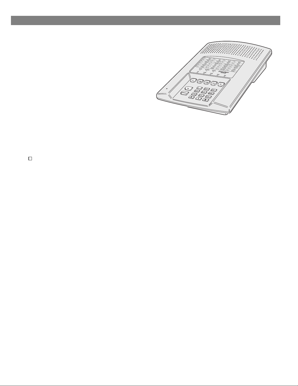
1. THE DVS-2400 SECURITY SYSTEM
DVS-2400
CONSOLE
DXS-32
DOOR/WINDOW
SENSOR
DXS-31
DOOR/WINDOW
SENSOR
DXS-10
WIRELESS
KEYPAD
DXS-81
BILL TRAP
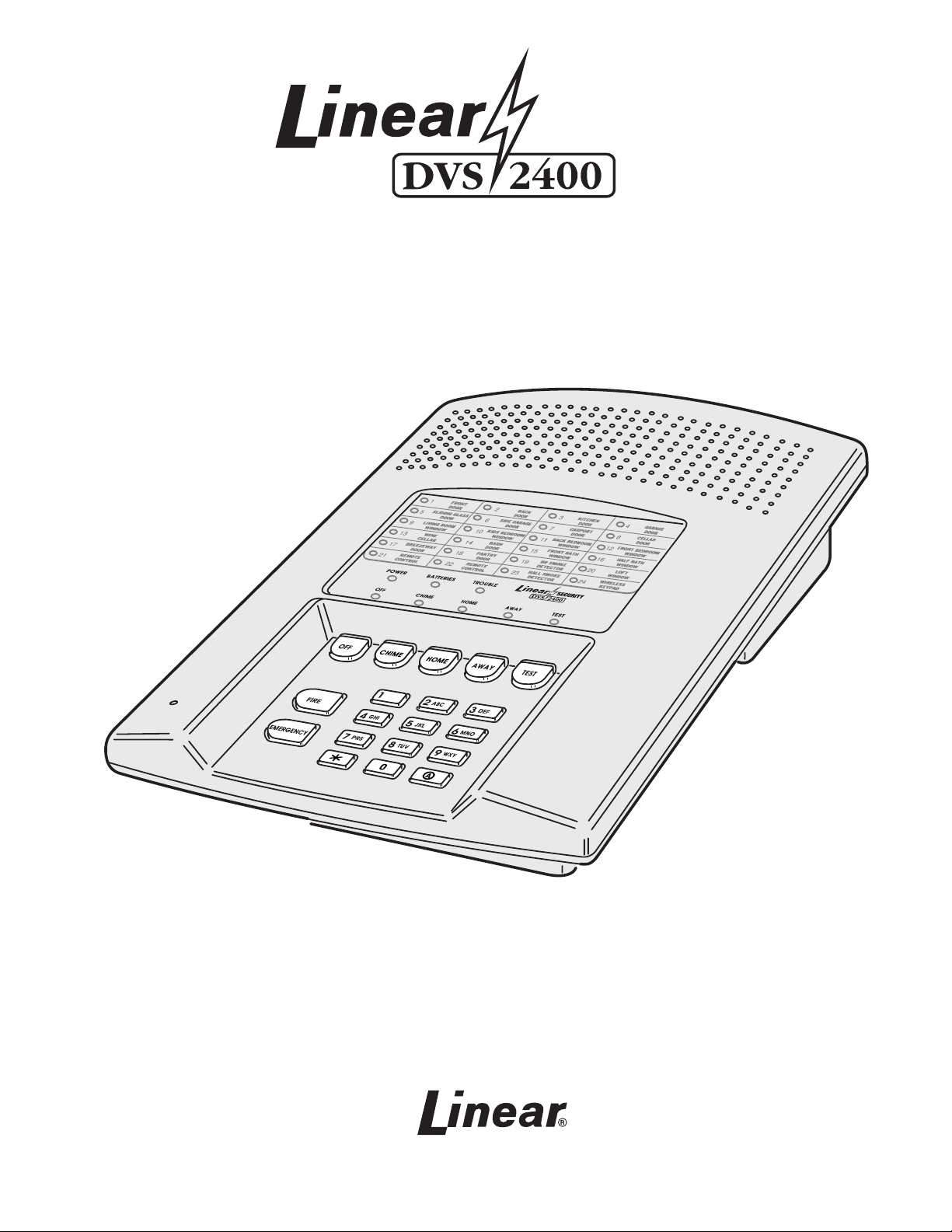
CONSOLE
The DVS-2400 Console is the heart of the system. It monitors
all of the system’s wireless sensors and controls the alarm
sirens.
The Console constantly monitors the condition of the system’s
sensors, displaying which protected doors and windows are
open or closed. If an alarm occurs, the Console displays which
sensor(s) caused it. When a sensor has a low battery, the
Console displays which sensor needs a new battery. Sensors
that send hourly status transmissions keep the Console
informed of their operating condition.
Up to eight different custom user codes can be used to operate
the system. For security, a user code must be entered to disarm
(turn off) the system. The system can be armed (turned on) by
entering a user code, or with the unique “Quick Arm” feature.
The five restricted user codes and the special page alert user
code can only arm and disarm the system, no programming
changes are allowed. The master user code is allowed to
program the Console, and a duress code can be selected for
emergency disarming of the system with a duress report to the
Central Station. The page alert user code can dial a pager
number to inform the pager wearer when the Console is
disarmed.
The Console’s memory will retain the user codes and all of the
system’s programming, even during a total power loss. An
optional backup battery can be installed to power the system
during short power failures.
The built-in digital communicator connects the Console to a
Central Alarm Monitoring Station through the telephone. With
a monitored system, the central station can dispatch authorities
in case of burglary, fire or other emergency. The central station
can also call family, friends, neighbors, or anyone else
designated on a custom call list.
Each sensor can report directly to the Central Station using the
digital communicator’s Point ID feature. If a sensor triggers an
alarm or experiences supervisory trouble, a unique report code
can be sent for immediate identification of the event.
The optional Models VB-2 or VB-3 digital voice synthesis
modules can be installed in the Console. The VB-2 module
provides three exciting features: 2-way audio monitoring
DXT-41 & DXT-42
REMOTES
DXS-54
PIR
DXS-62 & DXS-63
REMOTES
DXT-21 & DXT-23
REMOTES
DXS-91 GLASS
BREAK DETECTOR
DXS-21 & DXS-23
REMOTES
DXT-61
REMOTE
DXS-72
SMOKE DETECTOR
capability at the Central Station through the communicator,
local human voice prompts from the Console’s speaker, and
voice prompted remote system control using in-house or
off-site pushbutton telephones. The economy Model VB-3 is
the same as the VB-2 without 2-way Central Station audio
capability.
The Console has 24-hour capabilities that are always ready to
operate, even when the Console is disarmed. They can be
triggered by buttons on the Console, the Wireless Keypad,
portable remote controls and smoke detectors. Pressing the
[
EMERGENCY
immediate siren and call the central station.
] or [
] button for two seconds will cause an
FIRE
IMPORTANT: For
personal emergency use only.
The Console’s Environmental feature is active 24-hours and can
be triggered with sensors connected to devices such as water flow
detectors, over/under temperature sensors, flood sensors, toxic
gas detectors, etc. The Environmental feature activates the
chime annunciator without sounding the siren. The
Environmental feature does not send communicator reports.
An Automation Output in the Console provides an easy way to
connect external devices to the Console. The output is fully
programmable to activate on a variety of conditions, such as
when the system is armed, during alarms, and during exit/entry
delays. The Automation Output can connect to lighting control
modules, relays, noisemakers, and indicators. The Console’s
and wireless keypad’s (A) key and transmitters can control the
Automation Output.
The Console can be programmed locally using its own keypad
or remotely, over the telephone, using Linear’s Model RA-2400
Remote Access software program. The RA-2400
upload/download program is a Windows application that runs
on a personal computer and communicates with the Console
through a modem, connected directly to the Console or through
the telephone line.
2
Page 5
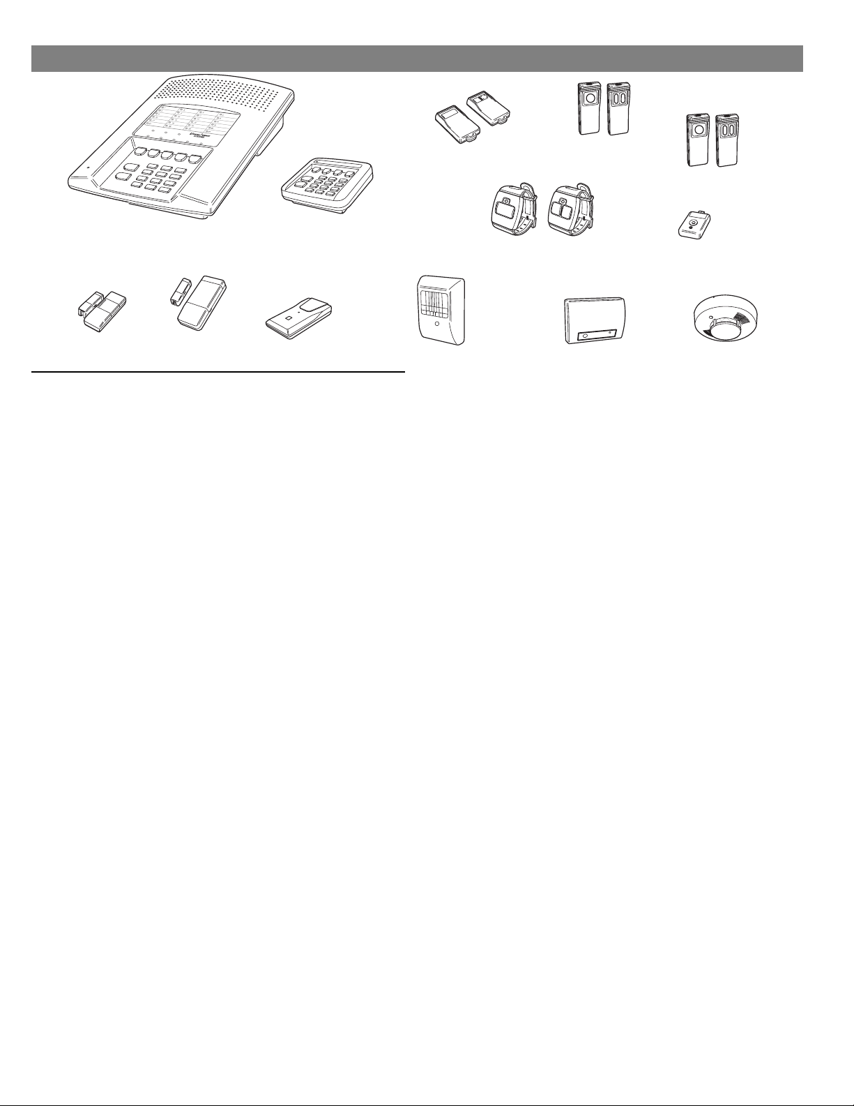
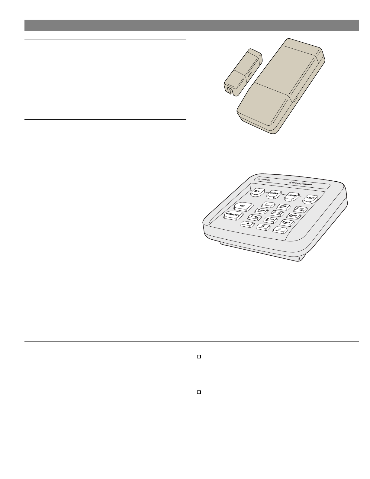
DOOR/WINDOW SENSORS
The DXS-31 & DXS-32 sensors monitor doors and windows. They
send radio signals to the Console. One type of signal is sent when
the door or window is opened, and a different type of signal is sent
when the door or window is closed. If the Console is armed, a
sensor can trigger the Console’s burglary siren when its door or
window is opened. Both sensors are supervised, and send hourly
status reports and monitor battery condition.
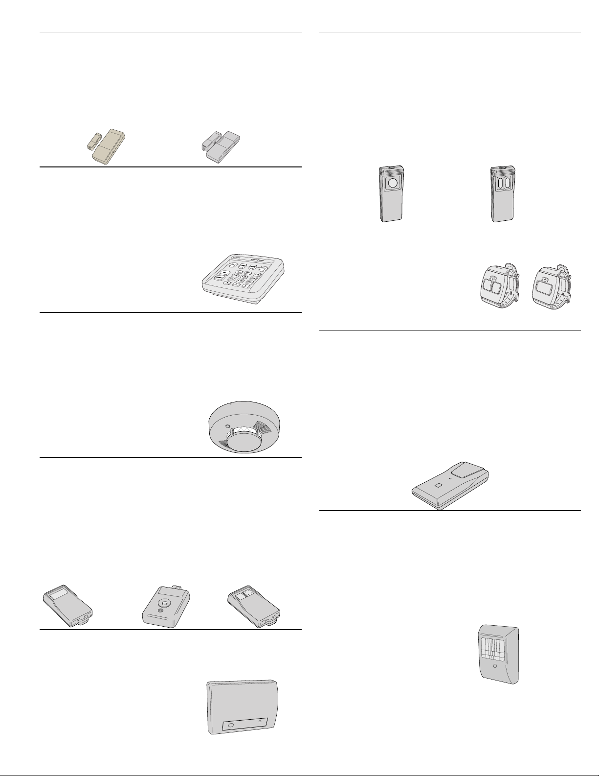
DXS-31
DXS-32
WIRELESS KEYPAD
The DXS-10 wireless keypad is used to control the Console
remotely. It can be placed in a convenient spot so the user
doesn’t have to go to the Console to control the system. The
wireless keypad can also trigger the emergency or fire siren and
actuate the Automation Output. Pressing the [∗] key will cause
the Console to sound beeps corresponding to the current
operating mode. The DXS-10 is
supervised, it sends hourly status
reports and monitors its battery
condition.
DXS-10
SMOKE DETECTORS
The DXS-72 is a high quality smoke detector with a built-in radio
transmitter. As soon as smoke is detected, the unit will sound its
local noisemaker. Then, 20 seconds after the local noisemaker
sounds, the transmitter sends an alarm signal to the Console. The
alarm signal will be repeated every 20 seconds as long as smoke is
still present. A restoral signal will be sent when the smoke detection
chamber clears. The DXS-72 is
supervised, and sends hourly status
reports and monitors battery
condition.
DXS-72
REMOTE CONTROLS
The DXT-41, DXT-61 single-button and DXT-23, DXT-42
multi-button remote controls can be used to remotely arm and
disarm the Console. The DXT-42’s left button will arm and the
right button will disarm the Console. Pressing both buttons
simultaneously on the DXT-42 will trigger the emergency siren.
Alternately, the console can be programmed to respond to the
DXT-42 by arming and disarming with the left button, and
activating the automation output with the right button. Each
transmitter can be programmed to activate various other
DXT-61
not
supervised.
DXT-42
Console functions. These transmitters are
DXT-41
GLASS BREAK DETECTOR
The DXS-91 is a glass break detector with an audio sound
discriminator and a built-in radio transmitter. The unit “listens”
for the sound of breaking glass.
When glass breakage is detected,
the unit sends an alarm signal to
the Console. The DXS-91 is
supervised, it sends hourly status
reports and monitors its battery
DXS-91
condition.
PANIC BUTTONS
The DXT-21, DXS-21 single-button and DXT-23 and DXS-23
two-button transmitters can be used as portable “panic
buttons”. Pressing the front or top button on the DXT-21,
DXS-21 at any time will trigger the emergency siren. Pressing
both
front buttons
simultaneously
on the DXT-23 & DXS-23
at any time will trigger the emergency siren. These transmitters
can be programmed to activate various other Console
functions. The DXT-21 and DXT-23 transmitters are
supervised. The DXS-21 and DXS-23 transmitters
not
are
supervised.
DXT-21
DXS-21
DXT-23
DXS-23
The DXS-62 and DXS-63 transmitters can be used as portable
“panic buttons”. Pressing the single button on the DXS-62, or
pressing both buttons on the
DXS-63, at any time will trigger the
emergency siren. These supervised
transmitters send hourly status
signals and low battery signals if the
battery is low.
DXS-62
DXS-63
BILL TRAP
The DXS-81 bill trap can be used with the Console in small
commercial hold-up installations. The unit is concealed in a
cash drawer under a stack of currency, with a single “bait” bill
secured in its money clip. During a hold-up, the cashier
removes the stack of currency along with the “bait” bill. When
a “bait” bill is removed, the transmitter sends a signal to the
Console. Four additional signals are sent within the first minute
after the “bait” bill is removed. When the “bait” bill is replaced,
a restore signal is sent. The DXS-81 is supervised, it can send
hourly status reports (optional) and monitors its battery condition.
DXS-81
PASSIVE INFRARED MOTION DETECTOR
The DXS-54 is a passive infrared (PIR) motion detector with a
built-in radio transmitter. The PIR detects motion in its detection
pattern by measuring the infrared emission levels of objects that
it “sees”. If the infrared levels change quickly, as when a person
moves across the detection pattern, the PIR will recognize the
change as an intrusion and send an alarm signal to the Console.
An alarm will be triggered if the Console is in the Away Mode.
The DXS-54 is supervised, it
sends hourly status reports
and monitors its battery
condition.
DXS-54
3
Page 6
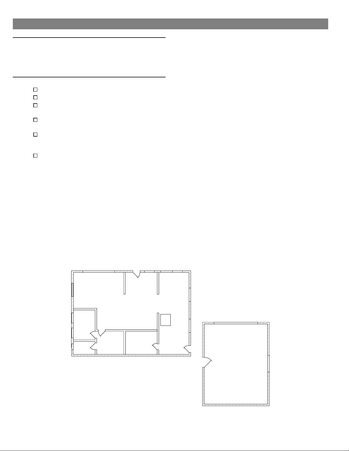
2. SECURITY SYSTEM FLOOR PLAN
EXAMPLE SYSTEM
The example shows a typical DVS-2400 system.
◆
Any or all of the accessories shown can be used.
◆
A total of 24 sensors (including keypads) can be
◆
used with each Console.
DESIGN THE INSTALLATION
Create a floor plan of the installation.
Consider the security needs of the premises.
Determine which doors and windows are
vulnerable to intrusion.
Figure which interior areas an intruder might go
to if unlawful entrance is gained.
Indicate locations for door/window sensors,
interior motion detectors, keypads, glass break
detectors and external siren speakers.
Decide on a centralized location for the security
Console.
ES
SD
GB
DEN
WK
S
ENTRY
DINING
BED
S
KITCHEN
CON
MD
LIVING
S
BED
S
MS
BATH
S
NOTE: IN NEW CONSTRUCTION, NFPA 71 REQUIRES A
SMOKE DETECTOR LOCATED INSIDE EACH BEDROOM
AS WELL AS A SMOKE DETECTOR ON EACH LEVEL.
Example Residential Security System Floor Plan
MS
MS
CON - CONSOLE
S - DOOR/WINDOW SENSOR
WK - WIRELESS KEYPAD
MD - MOTION DETECTOR
ES - EXTERNAL SIREN
SD - SMOKE DETECTOR
S
GB - GLASS BREAK SENSOR
MS - EXTERNAL MAGNETIC SWITCH
S
S
GARAGE
S
GB
MD
4
Page 7
3. TYPICAL SYSTEM SENSORS
DOOR/WINDOW SENSOR
Sensor mounts on door or window with adjacent
◆
magnet.
Opening door or window moves magnet away,
◆
triggering sensor.
Internal lithium batteries are monitored by the
◆
Console.
Sends hourly status reports to the Console.
◆
Up to 3 years battery life (depends on frequency
◆
of activation).
WIRELESS KEYPAD
For controlling the system without having to go
◆
to the Console.
Emergency and fire alarm can be triggered from
◆
wireless keypad at any time.
Green operation light.
◆
Internal 9-volt battery is monitored by the
◆
Console.
Keypad’s beeper will buzz during transmissions
◆
when the battery is low.
Up to 3 years battery life (depends on frequency
◆
of activation).
Sends hourly status reports to the Console.
◆
Press the [
◆
output.
Pressing [∗] clears the keypad.
◆
Holding [∗] for two seconds sounds the mode
◆
beeps from the Console.
Off Mode: 1 “Gong”
✔
Chime Mode: 1 “Gong” & 1 “Beep”.
✔
Home Mode: 1 “Gong” & 2 “Beeps”.
✔
Away Mode: 1 “Gong” & 3 “Beeps”.
✔
Test Mode: 1 “Bing” & 4 “Beeps”.
✔
] key to activate the automation
(A)
ABOUT SENSOR STATUS SUPERVISION
All DXS Format sensors transmit hourly status reports. All DXT
Format sensors do not transmit hourly status reports. Both
sensor formats can be used with the Console.
When a sensor is programmed into the Console, the Console
will set the sensor as non-supervised or supervised. Sensors
set as non-supervised are not expected to send hourly status
reports. Sensors set as supervised are expected to send
hourly status reports. If a status report is not received in 8
hours from a sensor set as supervised, the
indicator will flash.
When sensors are programmed into the Console,
STATIONARY SENSORS ARE SET AS SUPERVISED, ALL
PORTABLE SENSORS ARE SET AS NON-SUPERVISED.
TROUBLE
ALL
If stationary DXT Format sensors have been programmed
into the Console, be sure to change their setting to
non-supervised to prevent TROUBLE indications. This will
not prevent low battery monitoring.
If portable DXS Format sensors have been programmed
into the Console, and the installation requires supervision
for specific portable sensor(s), change the selected
portable sensors setting to supervised.
After programming the sensors, if changes are required, refer
to “Changing a Sensors Supervision” on Page 26 for details
on changing the way a sensor’s supervision is set.
5
Page 8
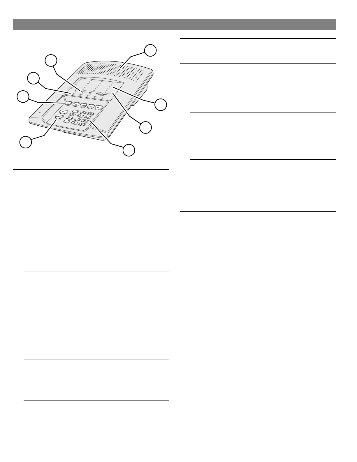
4. CONSOLE FEATURES
4
3
2
1
1 24-HOUR BUTTONS
2MODE BUTTONS
Pressing the [
★
a “fire” message to a central monitoring station through the digital
communicator (if the system is monitored).
Pressing the [
★
emergency siren and sends an “emergency” message to a central
monitoring station through the digital communicator (if the system is
monitored).
Both work even when system is disarmed.
★
★
IMPORTANT: For personal emergency use only.
Used to control the Console.
★
OFF
Off Mode disarms the system.
★
Switching to Off Mode stops the alarm siren.
★
Multiple beeps sound and status lights flash if an alarm has occurred.
✔
☞
Multiple beeps mean caution. AN INTRUDER MAY STILL BE PRESENT.
CHIME
Chime Mode disarms the system.
★
Switching to Chime Mode stops the alarm siren.
★
Multiple beeps sound and status lights flash if an alarm has occurred.
✔
☞
Multiple beeps mean caution. AN INTRUDER MAY STILL BE PRESENT.
Chime Mode is for monitoring doors and windows.
★
Use this mode as an “automatic door chime” when at home.
✔
Opening any protected door or window causes Console to “ding-dong”.
✔
HOME
Home Mode arms the perimeter sensors, but not the interior sensors.
★
Use this mode when anyone is staying behind.
✔
Interior motion detectors and interior door sensors are not armed.
✔
Home secure mode makes all delayed perimeter sensors instant.
✔
Secure exit mode starts an exit delay while remaining in Home Mode.
✔
Re-entering during the exit delay restarts the exit delay (one time only).
✔
AWAY
Away Mode arms the entire system.
★
Use this mode when leaving home.
✔
Door sensors set for “delayed” will have a delay that allows you to leave
✔
and enter the premises without sounding the alarm.
Re-entering during the exit delay restarts the exit delay (one time only).
✔
Entry Delay beeps warn you to disarm the system before the siren starts.
✔
TEST
Test Mode is for testing the system sensors.
★
All sensor status lights blink when the Test Mode is entered.
✔
Each sensor status light will stop blinking when its sensor is tested.
✔
Hold the [
★
TEST
5
7
8
] button for two seconds sounds the fire siren and sends
FIRE
EMERGENCY
] button down to test all of the Console’s indicator lights.
] button for two seconds sounds the
3 MODE INDICATORS
4 CONSOLE STATUS INDICATORS
6
5 SIREN SPEAKER
6 STATUS INDICATORS
7 CASE ACCESS SCREW (HIDDEN)
8 KEYPAD
Specific indicator will light showing the mode the Console is in.
★
HOME indicator will blink during secure exit and home instant modes.
★
AWAY indicator will blink during the exit delay in the Away Mode.
★
Show the current status of the Console.
★
POWER LIGHT
Glows when AC power is on.
★
Dims when AC power is off and backup battery is installed.
★
Blinks when the backup battery is low, recharging or missing.
★
Off when AC power is off and no backup battery is installed (system
★
disabled).
BATTERIES LIGHT
Blinks when one or more sensors has a low battery.
★
Press [∗] key for two seconds to view sensor status. Sensor status indicator
★
for any sensor with a low battery will light along with the BATTERIES
indicator.
Switch to Test Mode after replacing the sensor battery and completely test
★
the system (see Test Mode). Switching to Test Mode clears the low battery
indication.
TROUBLE LIGHT
Blinks when one or more sensors have not reported status during the eight
★
hour status time window.
Press [∗] key for two seconds to view sensor status. Sensor status indicator
★
for any sensor that has not reported in will light along with the TROUBLE
indicator.
Switch to Test Mode after servicing the sensor and completely test the
★
system (see Test Mode). Switching to Test Mode clears the trouble
indication.
Makes unique sounds for burglary, fire and emergencies.
★
Alarm sirens stop automatically after five minutes.
★
Sounds advisory tones to confirm keystrokes from the Console.
★
Sounds mode selections tones.
★
Sounds alarm memory tones.
★
Beeps when Automation Output is activated.
★
Speaks the system status information when optional VB-2 or VB-3 digital
★
voice synthesis module is installed.
Terminals available for an external siren.
★
Indicates the status of each of the system’s sensors.
★
Lights show which doors and windows are open.
★
Lights flash to display sensors that have caused an alarm.
★
Stick-on labels are provided to identify the custom sensor locations.
★
Remove clear display window and sensor identification card to gain access
★
to the screw.
Remove case access screw to unlock case. Case hinges open to the left.
★
Backlit keys for easy viewing in low light conditions.
★
For entering the user’s user code (numerically or alphabetically).
★
Used when programming system options.
★
Press [
★
Press the [∗] key to clear keypad if the wrong key is pressed.
★
Press and hold the [∗] key for one second to view sensor battery and
★
supervisory status (see BATTERIES and TROUBLE indicator description).
] key to activate Automation Output.
(A)
6
Page 9
13
14
15
16
11
10
22
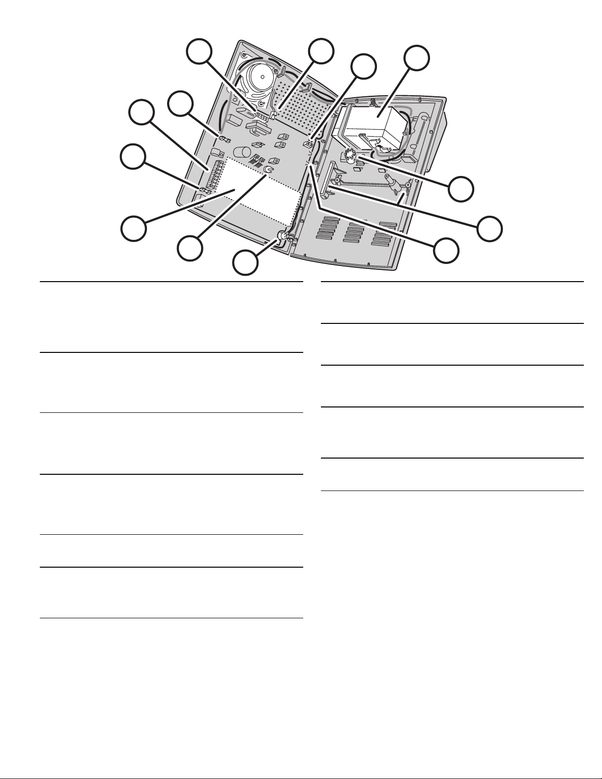
10 AUXILIARY FUSE
11 MAIN TERMINAL BLOCK
12 BATTERY FUSE
13 TELEPHONE TERMINAL BLOCK
14 INTERNAL SPEAKER CONNECTOR
15 ANTENNA TERMINALS
16 OPTIONAL BACKUP BATTERY
Type 2AG, 1-amp fuse.
★
Protects the external relay output when used with wet contacts (12 VDC
★
switched out).
Fuse will blow when load exceeds 1 amp.
★
WARNING: For continued protection against the risk of fire, replace
✍
only with the same type and rating of fuse.
Terminals for connection to the plug-in AC transformer.
★
Terminals for connection to an external speaker.
★
Automation Output to connect to an automation controller.
★
External relay output for “wet” contacts (switched 12 volts) or “dry” contacts
★
(normally open 1 amp @ 24 volts maximum).
Type 2AG, 3-amp fuse for the backup battery.
★
If the POWER light is flashing and the optional backup battery is installed
★
and charged, check this fuse.
WARNING: For continued protection against the risk of fire, replace
✍
only with the same type and rating of fuse.
Provides telephone connections for the digital communicator.
★
Provides telephone connection for voice prompted telephone remote control
★
(optional VB-2 digital voice synthesis module required).
Provides seized ring and tip connections for local telephone instruments.
★
Communicator will disconnect local telephones while on-line.
Connects the internal speaker to the Console circuit board.
★
2-pin connector, non-polarized.
★
Antenna and ground terminals for receiving signals from the system’s
★
sensors.
Pre-wired to the Console’s internal wire dipole antenna.
★
Alternately connects to the Model LA-P local whip and remote antenna kit.
★
Space for 12-volt, 1.2 amp/hour backup battery. (Highly recommended.)
★
Backup battery is automatically charged and monitored by the Console.
★
Backup battery can power the Console for up to 6 hours.
★
12
21
20
17
18
19
17 WIRING ACCESS HOLE
18 WALL-MOUNT SLOTS
19 RADIO TEST POINTS
20 MICROPHONE (WITH MODEL VB-2 INSTALLED ONLY)
21 ANNUNCIATOR VOLUME CONTROL
22 DIGITAL VOICE SYNTHESIS MODULE (OPTIONAL)
Provides access to recessed wiring trough in base of Console.
★
Route cables for power, telephone, external speaker, etc. through this hole.
★
Loop for zip-tie strain relief provided next to hole.
★
Used when mounting Console recessed in the wall.
★
Two mounting brackets (supplied) slide through slots and are retained by
★
screws, clamping the unit to the wall.
Used to monitor the Console’s radio receiver during troubleshooting.
★
Provides connection for an audio amplifier to listen to the receiver’s output.
★
Helpful to determine sources of radio interference.
★
High sensitivity microphone.
★
Detects room audio when communicator is reporting to the Central Station
★
in 2-way audio mode (Model VB-2 digital voice synthesis module must be
installed).
Varies the volume of the advisory tones that come from the speaker.
★
Does
★
★
★
★
★
affect internal or external sirens (they are always full volume).
not
Two voice synthesis modules are available, the Model VB-2 and VB-3.
Both modules allow remote command of the Console using a standard
pushbutton telephone, on or off site.
Both modules provide optional human voice prompts from the Console’s
speaker.
The Model VB-2 gives the Console’s digital communicator listen-only,
manual 2-way and full duplex 2-way audio capability with the Central
Station.
7
Page 10
5. CONSOLE INSTALLATION
CONSOLE LOCATION
NOTE: Sensor signals must be able to reach the
✍
Console.
Try to centrally locate the Console.
✔
Keep Console away from large metal
✔
appliances.
Maximum recommended sensor range is
✔
400 feet (system tested at 1000 feet).
NOTE: If you don’t use the Wireless Keypad, the
✍
Console should be easily accessible to the usual
entrance.
When the Console is set in the Away Mode,
✔
the user has 30 seconds to switch to Off
Mode before the burglary siren sounds.
NOTE: Make sure the Console is in a place where
✍
the alarm can be heard during the night hours.
Optional remote external sirens (up to 150
✔
feet from the Console) can be used to make
alarms louder and remote their location.
Locate the Console near an AC power outlet
that’s not controlled by a light switch.
Locate the Console near a telephone outlet (if
using the digital communicator).
USE A PAPER
CLIP TO REMOVE
THE CLEAR
DISPLAY WINDOW
REMOVE SENSOR
NAMEPLATE TO
ACCESS CASE
SCREW
REMOVE CASE
LOCKING SCREW TO
ACCESS INTERNAL
COMPONENTS
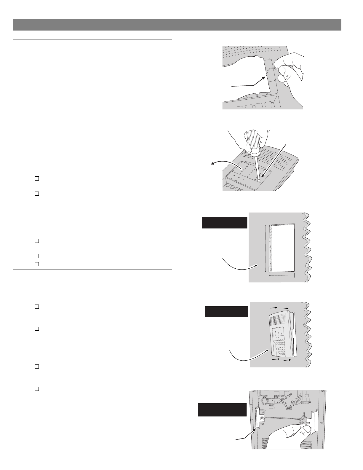
CASE LOCKING SCREW
To access the Console’s internal components or
◆
to prepare the Console for wall mounting, the
case locking screw needs removing.
Use a paper clip to remove the clear plastic
display window.
Remove the sensor number nameplate.
Remove the case locking screw.
WALL MOUNTING
If desired, the Console can be surface mounted
◆
or recessed into the wall.
Surface Mounting
For surface mounting, use the Console’s case
bottom as a template and mark the locations for
the four mounting screws.
Use four screws and appropriate screw anchors
to temporarily mount the unit to the wall (the unit
will need to be removed to complete the
recessed wiring hook up).
Recessed Mounting
For recessed wall mounting, cut a 10" by 6-3/4"
hole, centered between studs, in the mounting
wall at a convenient height.
Slide the unit into the mounting hole and
temporarily secure it with the two retaining
clamps and screws provided (the unit will need
to be removed to complete the recessed wiring
hook up).
FOR RECESSED
WALL MOUNTING ONLY
CUT A 10" x 6 3/4"
HOLE CENTERED
BETWEEN STUDS
IN MOUNTING WALL
AT A CONVENIENT
HEIGHT
FOR RECESSED
WALL MOUNTING ONLY
SLIDE CONSOLE
INTO WALL OPENING
FOR RECESSED
WALL MOUNTING ONLY
10"
6 3/4"
8
SECURE CONSOLE
TO WALL USING THE
TWO CLAMPS AND
SCREWS PROVIDED
Page 11
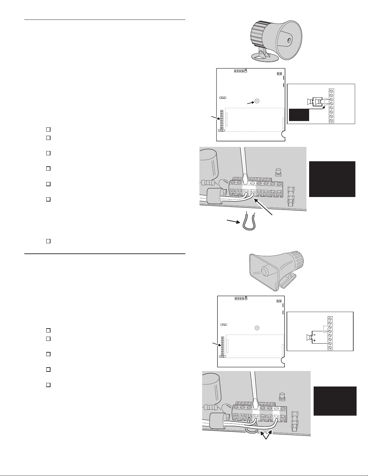
EXTERNAL CONSOLE SPEAKER CONNECTION (OPTIONAL)
An external console speaker sounds system
◆
tones and alerts occupants with a loud siren
during alarm.
With the VB-2 module installed, the Central
◆
Station can talk to the occupants through the
external console speaker.
Use an 8-ohm, 10 watt minimum rated speaker.
◆
Do not use a horn/siren with a built-in siren
driver.
Up to two 8-ohm speakers can be used with
◆
each Console.
Up to 150 feet of 22 AWG wire can be used with
◆
each speaker.
Mount the external speaker.
Route the speaker wires from the external
speaker to the Console.
Open the Console top cover and locate the main
terminal block.
Route the speaker wires up through the wiring
access hole.
Remove the wire jumper from the EXT. SPKR &
(-) terminals.
Connect the speaker wires to the EXT. SPKR &
(-) terminals.
NOTE: If connecting two external speakers,
✍
connect the second speaker in parallel, to the
same EXT. SPKR & (-) terminals as the first
speaker.
The system tone volume can be adjusted with
the annunciator volume control.
MAIN
TERMINAL
BLOCK
REMOVE
JUMPER
LINEAR SECURITY CONSOLE MODEL DVS-2400
ANNUNCIATOR
VOLUME
CONTROL
OPTIONAL
VOICE MODULE
MODEL: VB-2 OR VB-3
CONNECT SPEAKER LEADS
TO EXT. SPKR & (-) TERMINALS
EXT. SPKR(S)
8 OHM/10 WATT
2 SPKRS MAX.
NOTE: REMOVE
JUMPER FOR
EXT. SPEAKERS
EXTERNAL
CONSOLE
MAIN TERMINAL BLOCK
EXTERNAL
CONSOLE
SPEAKER
8 OHM, 10 WATT
MINIMUM
AC
AC
EXT. SPKR
(-)
H/A H/A +
RELAY N.O.
RELAY DRY
EXTERNAL ALARM SIREN CONNECTION (OPTIONAL)
An external siren alerts occupants and neighbors
◆
with a loud siren during alarm.
Use a 12 volt, 1 amp maximum rated
◆
weather-resistant horn speaker with a built-in
siren driver. Do not use a plain speaker.
NOTE: Connection of an electromechanical bell or
✍
motor bell is not recommended because of the
radio interference generated when the bell is
running.
Mount the external siren.
Route the wires from the external siren to the
Console.
Open the Console top cover and locate the main
terminal strip.
Route the siren wires up through the wiring
access hole.
Connect the siren wires to the RELAY N.O. & (-)
terminals.
NOTE: By removing the Console’s auxiliary fuse,
✍
the relay contacts will become isolated. Use the
RELAY N.O. & RELAY DRY terminals to switch an
externally powered load.
MAIN
TERMINAL
BLOCK
LINEAR SECURITY CONSOLE MODEL DVS-2400
OPTIONAL
VOICE MODULE
MODEL: VB-2 OR VB-3
MAIN TERMINAL BLOCK
EXTERNAL SIREN
12 VDC 1 AMP
MAXIMUM
EXTERNAL
ALARM
AC
AC
EXT. SPKR
(-)
H/A H/A +
RELAY N.O.
RELAY DRY
EXTERNAL
ALARM RELAY
12 VDC 1 AMP
MAXIMUM
CONNECT SIREN LEADS TO
(-) & RELAY N.O. TERMINALS
9
Page 12
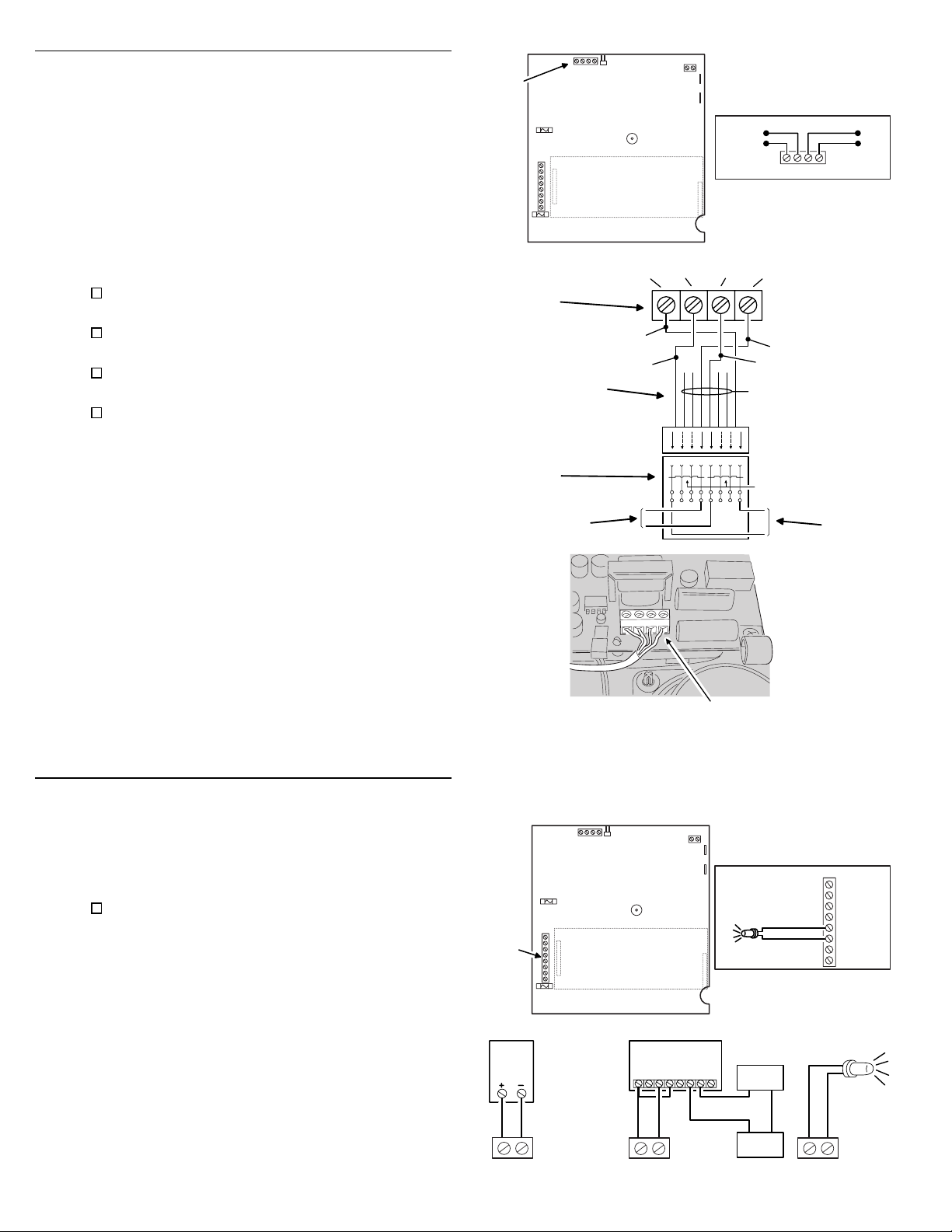
TELEPHONE LINE CONNECTION (OPTIONAL)
Connect the Console to the telephone line if the
◆
system is monitored, requires 2-way audio, or
requires telephone remote command.
Telephone ring & tip terminals are for connection
◆
to the incoming telephone line.
Seized telephone ring & tip are for connection to
◆
local telephone sets. When the communicator
activates, all the local telephone sets will be
disconnected to prevent an off-hook telephone
on the premises from blocking the
communicator call.
Install a USOC RJ31-X or RJ38-X jack to the
telephone system near the Console.
Route an appropriate modular telephone line
cord from the jack to the Console.
Route the line cord through the Console’s wiring
access hole.
Connect the incoming telephone line wires to the
Console’s telephone terminal block TIP and
RING terminals.
Connect the local telephone set wires to the
◆
Console’s telephone terminal block SEIZED TIP
and SEIZED RING terminals.
When directly connecting (without a telephone
◆
line) to the DVS-2400 with the RA-2400 remote
access software (Version 1.3 or later),
disconnect the incoming telephone line and
connect the modem to the panel’s TIP and RING
terminals (with the modem’s red & green phone
line wires). Press the [
EMERGENCY
Test Mode to cause the panel to connect to the
modem.
] key while in
TELEPHONE
TERMINAL
BLOCK
DVS-2400
TELEPHONE
TERMINAL
BLOCK
8-POSITION
USOC RJ31-X
(OR RJ38-X)
JACK
TO TELEPHONE
NETWORK
LINEAR SECURITY CONSOLE MODEL DVS-2400
OPTIONAL
VOICE MODULE
MODEL: VB-2 OR VB-3
8-PIN
MODULAR
PHONE CORD
SEIZED
TIP (T1)
BROWN
GRAY
SEIZED
RING (R1)
R1
1324567
R
T
TIP (T)
R
TELEPHONE TERMINAL BLOCK
SEIZED RING
SEIZED TIP
TO LOCAL
PHONES
LINE
LINE
RING (R)
GREEN
BLUE, ORANGE
BLACK, AND
YELLOW NOT
USED
T
T1
SHORTING BAR
SHORT REMOVED
ON PLUG
8
INSERTION
T1
R1
RED
T1
TO PHONE
RTR1
LINE
TO LOCAL
TELEPHONE
SETS
TIP
RING
AUTOMATION OUTPUT CONNECTION (OPTIONAL)
The Console provides a Automation Output to
◆
control lights, devices and appliances.
Automation Output can connect to most popular
◆
home automation devices and other simple
electronic devices (see Figure).
Press [
press [
] to turn the Automation Output on,
(A)
] again to turn it off.
(A)
Programmable Options
There are many programmable options for the
◆
Automation Output.
The Automation Output can be programmed for
◆
a variety of useful functions, such as: flashing
during alarm, flashing after an alarm, on while
armed, or, on during exit/entry delays.
See the “Advanced Programming” section of this
◆
manual for details on changing the function of
the Automation Output.
MAIN
TERMINAL
BLOCK
X-10
H/A + H/A -
CONNECT TELEPHONE LINE
TO THE TELEPHONE
TERMINAL BLOCK
MINUS H/A TERMINAL WILL SWITCH
TO GROUND WHEN AUTOMATION
LINEAR SECURITY CONSOLE MODEL DVS-2400
OPTIONAL
VOICE MODULE
MODEL: VB-2 OR VB-3
EXAMPLE AUTOMATION OUTPUT HOOK-UPS
X-10
BURGLAR ALARM
INTERFACE
(CAN CONTROL
HOUSE LIGHTS
THROUGH X-10
SYSTEM)
LINEAR RB-90
RELAY MODULE
H/A + H/A - H/A + H/A -
OUTPUT IS ACTIVATED
POSITIVE H/A TERMINAL PROVIDES
+12 VOLTS DC AND IS CURRENT
LIMITED AT 30 MILLIAMPS MAXIMUM
MAIN TERMINAL BLOCK
LIGHT EMITTING
DIODE (L.E.D.)
YOUR
LOAD
POWER
SOURCE
AC
AC
EXT. SPKR
(-)
H/A H/A +
RELAY N.O.
RELAY DRY
LIGHT
EMITTING
DIODE
(L.E.D.)
10
Page 13
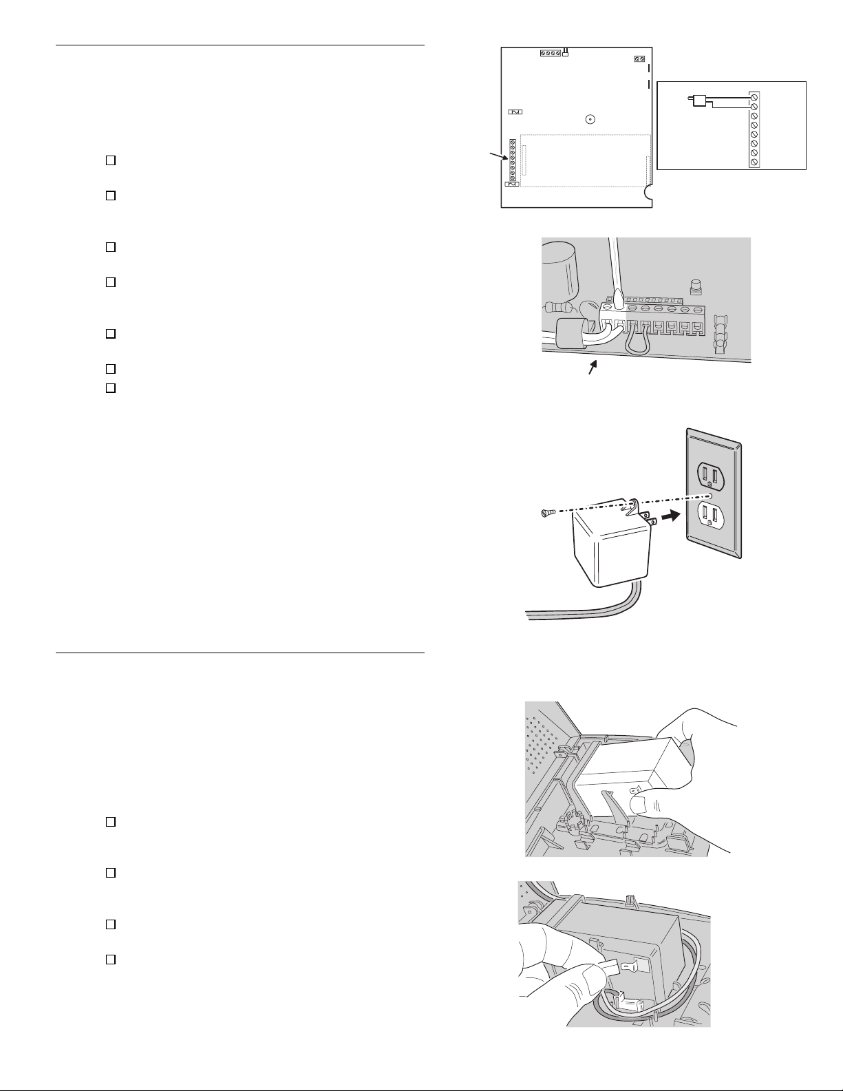
CONSOLE POWER CONNECTION
The Console is powered by a low voltage plug-in
◆
transformer.
Use up to 25 feet of 20 AWG or larger
◆
two-conductor wire to connect the transformer to
the Console.
Route the power wires from the plug-in
transformer to the Console.
Connect the wires to the transformer terminals
(do not plug the transformer in until the wiring
is complete)
.
Route the power wires through the Console’s
wiring access hole.
Connect the power wires from the transformer to
the Console’s main terminal block AC & AC
terminals.
Secure all of the wires entering the Console with
a zip-tie to the Console’s strain relief loop.
Plug transformer into an
Secure transformer with screw to prevent
un-plugging.
unswitched
AC outlet.
MAIN
TERMINAL
BLOCK
LINEAR SECURITY CONSOLE MODEL DVS-2400
OPTIONAL
VOICE MODULE
MODEL: VB-2 OR VB-3
CONNECT TRANSFORMER LEADS
TO AC POWER TERMINALS
PLUG TRANSFORMER
INTO AC POWER OUTLET
THAT IS NOT CONTROLED
BY A LIGHT SWITCH
MAIN TERMINAL BLOCK
PLUG-IN TRANSFORMER
16 VAC, 28 VA
OUTPUT RATING
AC
AC
EXT. SPKR
(-)
H/A H/A +
RELAY N.O.
RELAY DRY
BACKUP BATTERY INSTALLATION (OPTIONAL)
A 12 volt backup battery may be installed and is
◆
highly recommended.
The backup battery will power the Console for
◆
up to 6 hours during AC power loss.
The backup battery is automatically charged by
◆
the Console when AC power is present.
A low backup battery will cause the Console
◆
POWER indicator to flash as it is being charged.
To install the battery, slide the battery between
the retaining clamps and under the battery
holder.
Position the battery until the clamps snap in
place. The battery terminals should be facing the
center of the Console case bottom.
Connect the black battery lead to the black
battery terminal.
Connect the red battery lead to the red battery
terminal.
WARNING: DO NOT REVERSE THE BATTERY
✍
LEADS! THE BATTERY FUSE WILL BLOW.
SCREW
AC POWER
OUTLET
TRANSFORMER
SLIDE BACKUP BATTERY
INTO BATTERY CLAMPS
CONNECT RED BATTERY LEAD TO RED TERMINAL
CONNECT BLACK BATTERY LEAD TO BLACK TERMINAL
CAUTION: DO NOT REVERSE BATTERY LEADS
BATTERY FUSE WILL BLOW
11
Page 14
6. BASIC CONSOLE PROGRAMMING
In a new installation,
◆
when power is first applied
the Console’s master user code is “1234”.
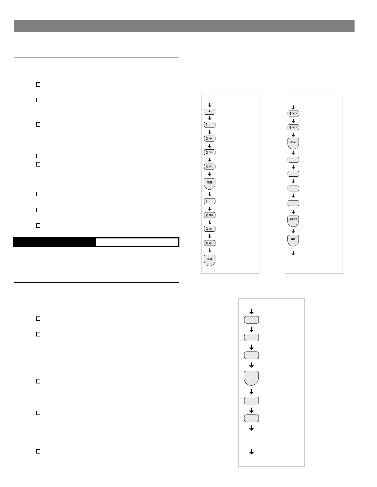
CREATE THE MASTER USER CODE
NOTE: Local programming must be entered on the
✍
Console’s keypad, not on a wireless remote keypad.
Press [∗] (clears keypad if any other keys have
been pressed).
Place the Console in Test Mode (enter 1234 and
press [
A “gong” and four “beeps” will sound.
❇
TEST
].
Enter the Setup Mode
1234
then press [
A “gong” and five “beeps” will sound. You are
❇
TEST
now in Setup Mode.
Enter 99 then press [
HOME
Enter any combination of 1-5 digits for the
master user code, then press [
NOTE: For maximum security, a three to five digit
✍
code is recommended.
Press and hold the [
OFF
exit program mode.
Test the new master user code by entering it
then pressing [
TEST
].
Log the master user code in the box below.
MASTER USER CODE
NOTE: The master user code can be used to enter
✍
Setup Mode. The restricted user codes cannot. To
create restricted user codes, see the “Advanced
Programming” section of this manual.
from Test Mode
, enter
] again.
].
].
AWAY
] key for 3 seconds to
ENTERING
SETUP
MODE
START IN OFF
CLEARS
KEYPAD
DEFAULT
MASTER
USER
CODE
1 GONG &
4 BEEPS
(TEST MODE)
DEFAULT
MASTER
USER
CODE
1 GONG &
5 BEEPS
(SETUP MODE)
SETTING A
NEW MASTER
USER CODE
START IN SETUP
PROGRAMMING
STEP #99
PROGRAM
NEW
MASTER
USER
CODE
STORE
CODE
HOLD FOR
3 SECONDS
TO EXIT
SETUP
DONE
PROGRAM THE SENSORS INTO THE CONSOLE’S MEMORY
Each wireless sensor that is going to be used
◆
with the Console must be programmed into the
Console’s memory.
Start with the Console in Test Mode (enter any
user code and press [
Enter the Setup Mode
master user code
A “gong” and five “beeps” will sound. You are
❇
then press [
]).
TEST
from Test Mode
] again.
TEST
, enter the
now in Setup Mode.
The sensor status indicators will light for any
❇
sensors programmed into the Console.
Enter an unused sensor number from 01-24
(you must enter two digits, example: 5 = 05)
The sensor indicator light will flash for the sensor
❇
number selected.
Activate the sensor by sending a test or alarm
signal (be sure the sensor’s battery is connected
or that its battery protection strip is removed).
A single “bing” tone will sound and the sensor
❇
status indicator for that sensor will stay lit.
Enter another sensor number or exit Setup Mode
by holding the [
] key for three seconds.
OFF
START IN TEST
MASTER
USER
CODE
1 GONG &
TEST
5 BEEPS
NEW
SENSOR
NUMBER
ACTIVATE
SENSOR
DONE
12
Page 15

PROGRAMMING DIFFERENT SENSOR TYPES
Follow the instructions on the previous page to
◆
select a sensor number to program the sensor
into.
NOTE: A sensor can be programmed into more
✍
than one location. Be sure to choose an unused
sensor number. If a sensor gets entered into more
than one location, delete the duplicates using the
remove sensor function.
To add DXS-10 wireless keypads,
hold the keypad’s [∗] key until programmed into
the Console.
IMPORTANT NOTE: The DXS-31 & DXS-32
✍
door/window sensors are pre-set at the factory for
delayed burglary response. If the sensor is going
to be used on a non-entry portal (window, sliding
glass door, etc.) a jumper can be changed in the
sensor to select instant response. The jumper
should be changed before learning the sensor so the
Console will program the sensor to the proper
function. See the “Basic Sensor Installation” section
of this manual for details on changing the jumper.
For DXS-31 and DXS-32 door/window sensors,
move the magnet away from the side of the
sensor.
For DXS-81, DXS-91, DXS-54, & DXS-72
accessory sensors, simply send a test
transmission (refer to the sensor’s instructions
for details on sending a test transmission).
For DXT-61, DXT-21, DXS-21 & DXT-41
single-button remotes, simply press the unit’s
button. The unit will function as an arm/disarm
remote.
NOTE: After the Console “learns” the transmitter,
✍
single-button remotes can easily be
re-programmed as “panic buttons” or home
automation controllers. Refer to Page 24 in the
“Customizing the System” section of this manual.
For DXT-23 & DXT-42 multi-button remotes: Learn
the transmitter by pressing the left button. The
remote will arm the Console with the left button and
disarm with the right. Labels are provided with the
DXT-42 for identifying the buttons.
NOTE: After the Console “learns” the transmitter,
✍
multi-button remotes can easily be re-programmed
to have the left button arm/disarm the Console and
the right button activate/deactivate the Home
Automation Output. Refer to Page 24 in the
“Customizing the System” section of this manual.
A single “bing” tone will sound and the sensor
❇
status indicator will stay lit when the sensor is
learned by the Console.
A double “buzz” tone will sound if there is
❇
already another sensor programmed to that
sensor number.
Exit Setup Mode by holding the [
OFF
two seconds. Reminder: The Console will
automatically exit the Setup Mode and return to
Off Mode after 3 minutes of keypad inactivity.
NOTE: To remove sensors from the Console’s
✍
memory, see Page 22 in the “Customizing the
System” section of this manual.
press and
] button for
SEND SIGNAL WITH LEFT BUTTON
LEFT = ARM
RIGHT = DISARM
BOTH = EMERGENCY
13
Page 16

7. BASIC SENSOR INSTALLATION
Each accessory sensor is packaged with its own
◆
set of installation instructions specific to the
model of sensor.
Refer to the sensor’s instructions for details on
◆
installing, operating, and testing of the sensor.
Following are basic instructions for installing two
◆
popular DVS-2400 accessories: The Model
DXS-10 Wireless Remote Keypad and the
Models DXS-31 & DXS-32 Door/Window
Transmitters.
DXS-10 WIRELESS KEYPAD
The DXS-10 is used to remotely command the
◆
Console.
The keypad can be simply set on a table or
◆
mounted to a flat surface.
TABLE-TOP USE
Four anti-mar pads are provided as a scratch
◆
deterrent for the keypad.
NOTE: Do not use the adhesive pads if the keypad
✍
is going to be wall mounted.
Peel off the adhesive tape backing on the pads
and stick them to the back of the keypad.
The wireless keypad can be used as a portable
◆
keypad. Because of the hourly supervisory
transmissions, if the unit is taken out of range
from the Console for more than eight hours, the
Console will indicate “radio trouble” for the
keypad. The keypad’s sensor number can be
programmed for “non-supervised” if required.
See the “Advanced Programming” section of this
manual.
WALL MOUNT USE
The wireless keypad can be wall mounted.
◆
Open the keypad by inserting a small
screwdriver in one of the top slots in the keypad
case. Gently twist the screwdriver until the case
pops open.
Attach the rear case to the wall using the two
screws provided.
NOTE: For best signal transmission, the keypad
✍
should be mounted at least three feet above
ground level.
Hook the top edge of the keypad case together
and snap the keypad onto the rear case.
WARNING: The wireless keypad is designed for
✍
indoor use only.
FROM TOP OF CASE TWIST
SCREWDRIVER BETWEEN
CASE HALVES UNTIL IT
POPS OPEN
CONNECT BATTERY
TO BATTERY CLIPS
USE THE FOUR SCRATCH
DETERRENT PADS PROVIDED
FOR TABLE-TOP USE
ATTACH REAR CASE TO WALL
WITH THE TWO SCREWS PROVIDED
14
MOUNT AT A CONVENIENT
LOCATION NEAR PRIMARY
ENTRY/EXIT DOOR
Page 17

DXS-31 & DXS-32 DOOR/WINDOW SENSORS
The DXS-31 and DXS-32 sensors can be used to
◆
monitor doors, windows, cabinets, crawl space
doors, gates, freezer doors, and many other
moving objects that could be used for intrusion
or need to be monitored.
A built-in magnetic switch triggers the sensor
◆
when its magnet (mounted on the moving part
or the door or window) moves away from the
sensor.
External normally closed switches (DXS-31
◆
only) can be wired to the sensor for remote
triggering.
The door/window sensor (DXS-31 only) can
◆
connect directly to a glass break detector.
SET SENSOR JUMPER
A jumper inside the door/window sensor selects
◆
instant or delayed response.
If the sensor is going to be used on the primary
entry/exit door make sure that the jumper is in
the DELAY position.
If the sensor is going to be used on a window or
a door that is not going to be used to enter and
exit the premises, set the jumper to the
INSTANT position.
APPLY DOUBLE-STICK TAPE
Apply double-stick tape (supplied) to back of
sensors and magnets.
Screws are also provided to mount sensors and
◆
magnets.
Screws are preferred over the double-stick tape
◆
in permanent installations.
ATTACH SENSORS AND MAGNETS
On doors, mount sensor to door frame and
magnet to door.
NOTE: Magnet must line up with mark on sensor
✍
case both horizontally & vertically.
Allow a maximum of 1/2" between magnet and
sensor when door/window is closed.
Snap sensor onto mounting plate.
On windows, mount sensor to window frame and
magnet to window.
Snap sensor onto mounting plate.
The magnet height is adjustable and an optional
magnet spacer is provided for uneven surfaces.
TEST SENSORS
Console in Chime Mode should “ding-dong”
❇
when the sensor sends signal.
Open door or window.
Verify that light on the sensor glows momentarily
❇
when door/window is opened.
Status indicator on Console should remain lit for
❇
each door/window sensor that is left open.
LEFT OPENING DOOR
TRANSMITTER
MOUNTED ON
DOOR JAMB
(NOTE: SMALL END
OF TRANSMITTER UP)
MAGNET
MOUNTED
ON DOOR
INPUT
SELECT
JUMPER
TRANSMIT
INDICATOR
TEST
SWITCH
INSTANT/DELAY
OPTION JUMPER
SELECTS
DELAY
NOTE: ATTACHING THE TRANSMITTER WITH DOUBLE-STICK
TAPE IS NOT ALLOWED IN UL INSTALLATIONS
OPEN DOOR, TRANSMIT
INDICATOR SHOULD LIGHT
EXAMPLE INSTALLATIONS
(WITH DXS-31 SHOWN)
SLIDING WINDOW
MAGNET MOUNTED
ON WINDOW FRAME
RIGHT OPENING DOOR
TRANSMITTER
MOUNTED ON
DOOR JAMB
(NOTE: SMALL END
OF TRANSMITTER DOWN)
MAGNET MOUNTED
ON DOOR
INSTANT/DELAY
OPTION JUMPER
MAGNET
ALIGNMENT
MARK
ATTACH MOUNTING PLATES
USING THE SCREWS OR
DOUBLE-STICK TAPE PROVIDED
ANTENNA
TWO TYPE 2032
BATTERIES
EXTERNAL
INPUT
TERMINALS
SELECTS
INSTANT
1. PLACE RECEIVER INTO
PROGRAM OR "LEARN" MODE
2. ACTIVATE TRANSMITTER
BY OPENING DOOR OR
WINDOW
3. VERIFY THAT THE
RECEIVER ACCEPTED THE
SIGNAL
4. REPLACE TRANSMITTER
COVER WHEN FINISHED
NOTE: THE TRANSMIT
INDICATOR WILL ONLY LIGHT
DURING TRANSMISSIONS
WHEN THE CASE IS OPEN
(EXCEPT WHEN PUSHING
THE CASE FOR TESTING)
BATTERY
CLAMP
SCREW
BATTERY CLAMP
TRANSMITTER
MOUNTED ON
WINDOW SILL
DOUBLE-HUNG
WINDOW
TRANSMITTER
MOUNTED ON
WINDOW FRAME
MAGNET
MOUNTED
ON WINDOW
SASH STILE
15
Page 18

8. CUSTOMIZING THE CONSOLE
The Console can be customized for the specific
◆
installation.
A label sheet with sensor location names is
◆
provided with the Console.
Labeling the sensors allows quick and easy
◆
identification of where any alarms have
occurred, where a sensor with a low battery is,
where a sensor with radio trouble is, etc.
LABELING THE SENSORS
Use a paper clip to remove the clear display
window.
Bend down the tabs on the sensor number card
and fit it onto the Console.
Open one protected door/window to light its
sensor status light on the Console.
Choose a label that describes the sensor
location, or write the location on a blank label,
and stick it in the area to the right of the sensor
light.
Close the protected opening that you just labeled.
Repeat for each protected opening.
Stick the WIRELESS KEYPAD label in the sensor
number location for the wireless keypad (if used).
Replace the clear display window when finished.
USE SENSOR
LABELS PROVIDED
BEND TABS DOWN
AND INSERT IN
SLOTS
WRITE IN SPECIAL
LOCATIONS ON
BLANK LABELS
APPLY SENSOR IDENTIFICATION
LABELS TO THE APPROPRIATE
SENSOR LOCATIONS
OPEN DOOR
OR WINDOW
TO LIGHT
SENSOR STATUS
INDICATOR
ON CONSOLE
16
Page 19

9. CONSOLE OPERATING MODES
OFF MODE
Use this mode to disarm the burglary portion of
◆
the system.
Switching to Off Mode stops any alarms in
◆
progress.
The 24-hour functions are still active in Off Mode
◆
and can be triggered by pressing the [
[
EMERGENCY
Switch to Off Mode by entering the user code,
and pressing [
When the system is disarmed to Off Mode, the
❇
Console will sound one “Gong”.
If an alarm has occurred, multiple beeps will
❇
sound after disarming and the sensor light for the
sensor(s) that caused the alarm will flash.
NOTE: In Off Mode, protected doors and windows
✍
cannot trigger the burglary alarm.
] button.
].
OFF
FIRE
] or
OFF MODE
START HERE
(OPTIONAL)
YOUR
USER
CODE
OFF
1 GONG
DONE
CHIME MODE
Chime Mode is for monitoring entries and exits
◆
without causing alarms.
Use Chime Mode as an “automatic door chime”
◆
when at home.
Opening any protected door or window causes
❇
the Console to sound a “ding-dong”.
Select the Chime Mode by entering a user code,
then press [
The user can enter Chime Mode from Off Mode
by holding down the [
seconds.
When the system is switched to the Chime
❇
Mode, the Console will sound a “Gong” and one
“Beep”.
Going to Chime Mode disarms the system and
◆
stops any alarms in progress.
NOTE: In Chime Mode, protected doors and
✍
windows cannot trigger the burglary alarm.
CHIME
].
CHIME
] key for two
CHIME MODE
START HERE
(OPTIONAL)
YOUR
USER
CODE
1 GONG
CHIME
& 1 BEEP
DONE
OR
START IN OFF
HOLD
DOWN
CHIME
1 GONG
& 1 BEEP
DONE
17
Page 20

HOME MODE
Use this mode when sleeping or when anyone is
◆
staying inside.
Home Mode causes an instant alarm when any
◆
perimeter sensor is triggered.
Home Mode causes a delayed alarm when any
◆
exit/entry sensor is triggered (except in Home
Instant Mode when they are instant).
Alarm siren stops automatically after five
◆
minutes and the system will remain armed.
Home Mode ignores all interior sensors (motion
◆
detectors, etc.).
Arm to Home Mode by entering a user code, and
pressing [
The user can “Quick Arm” to Home Mode from Off
or Chime Mode by holding down the [
for two seconds. (Quick arming can be disabled;
see the “Advanced Programming” section of this
manual.)
When the system is armed to the Home Mode,
❇
the Console will sound a “Gong” and two
“Beeps”.
Enter a user code and press [
disarm from Home Mode and/or stop the alarm
siren.
If an alarm has occurred, multiple beeps will sound
❇
after disarming and the sensor light for the
sensor(s) that caused the alarm will flash (switch to
Off Mode again or re-arm the Console to stop the
flashing alarm memory light).
SECURE EXIT
If the system is already in the Home Mode and
the user wants to exit the premises while leaving
someone inside
Mode
key.
A “gong” and two “beeps” will sound and the
❇
HOME light will blink for 60 seconds. No exit
delay beeps will sound during the Exit Delay.
The user can leave through a door with a delayed
◆
perimeter sensor during the 60 second Exit Delay
without causing the Console to begin an Entry Delay.
Re-entering during the silent Exit Delay will
◆
extend the Exit Delay another 60 seconds (one
time only).
NOTE: The Exit Delay time can be changed; see
✍
the “Advanced Programming” section of this
manual.
HOME INSTANT MODE
If the system is already in the Home Mode and
the user wants to make all exit/entry sensors
instant, press the [
Two “gongs” and two “beeps” will sound and the
❇
HOME light will blink continuously.
Because all exit/entry sensors will now cause an
◆
instant
must be disarmed before opening any exit/entry
delay door.
HOME
, enter a user code and press the [
alarm when in Home Mode, the Console
].
] key
HOME
] or [
OFF
with the system still in Home
] key for 2 seconds.
HOME
CHIME
HOME
] to
MANUAL BYPASSING OF SENSORS
Manual bypassing of sensors in the Home Mode
◆
allows arming of the system at night with open
windows, while still having perimeter protection
with other closed doors and windows.
The Console will resist arming with open door or
◆
window sensors.
Four high-low beeps to warn the user that
❇
something is open and the system will remain in
the previous mode.
Lit sensor status indicators show which sensors
❇
are open.
To manually bypass the open sensors, arm the
system again
A “gong” and two “beeps” will sound, the HOME
❇
indicator will light, and the open sensors will be
bypassed.
WARNING: Bypassed sensors cannot cause an
✍
alarm.
within 5 seconds
HOME MODE
START IN OFF
OR CHIME MODE
(OPTIONAL)
]
HOME
DONE
YOUR
USER
CODE
1 GONG
& 2 BEEPS
.
SECURE EXIT
START IN
HOME MODE
(OPTIONAL)
YOUR
USER
CODE
1 GONG
HOME
& 2 BEEPS
DONE
HOME INSTANT
QUICK ARM
START IN OFF
OR CHIME MODE
HOLD
DOWN
HOME
1 GONG
& 2 BEEPS
DONE
MODE
START IN
HOME MODE
HOLD
DOWN
HOME
2 GONGS
& 2 BEEPS
DONE
18
Page 21

AWAY MODE
Use this mode when no one will be staying home.
◆
Each burglary sensor can trigger the siren once
◆
per arming period.
Away Mode causes an
◆
perimeter sensor is triggered.
Away Mode causes a
◆
exit/entry sensor is triggered.
Away Mode causes an
◆
interior sensors (motion detectors, etc.) are
triggered. The interior sensors will be
perimeter delayed sensor is triggered first.
Alarm siren stops automatically after five
◆
minutes and the system will remain armed.
Arm to Away Mode by entering a user code, and
pressing [
The user can “Quick Arm” to Away Mode from
Home, Chime or Off Mode by holding down the
[
be disabled; see the “Advanced Programming”
section of this manual.)
EXIT DELAY (For Leaving the Premises)
When the system is armed to the Away Mode, the
❇
Console will sound a “Gong” and three “Beeps”.
During the 60 second Exit Delay, the Console
❇
will sound “beeps” (double beeps last 10
seconds) and the AWAY light will blink.
The Exit Delay gives the user
◆
leave the premises
without triggering an alarm.
Re-entering during the Exit Delay will extend the
◆
Exit Delay another 60 seconds (one time only).
When the Exit Delay is over, the Console will
❇
sound one “gong” to warn the user that the
system is fully armed.
NOTE: The Exit Delay time can be changed; see the
✍
“Advanced Programming” section of this manual.
instant
delayed
instant
].
AWAY
] key for two seconds. (Quick arming can
AWAY
through an exit/entry door
alarm when any
alarm when any
alarm when any
60 seconds
delayed
to
if a
MANUAL BYPASSING OF SENSORS
Manual bypassing of sensors in the Away Mode
◆
allows arming of the system with open doors and
windows, while still having perimeter protection
with other closed doors and windows.
The Console will resist arming with open door or
◆
window sensors.
Four high-low beeps to warn the user that
❇
something is open and the system will remain in
the previous mode.
Lit sensor status indicators show which sensors
❇
are open.
To manually bypass the open sensors, arm the
system again
A “gong” and three “beeps” will sound, the
❇
AWAY indicator will light, and the open sensors
will be bypassed.
WARNING: Bypassed sensors cannot cause an
✍
alarm.
within 5 seconds
AWAY MODE
START HERE
(OPTIONAL)
YOUR
USER
CODE
.
ENTRY DELAY (For Entering the Premises)
The Entry Delay gives the user
◆
enter the premises
without triggering an alarm.
If a exit/entry sensor is triggered, starting the
◆
Entry Delay, the interior sensors will also
become
premises during the Entry Delay).
During the 30 second Entry Delay, the Console will
❇
sound “beeps”.
When the Entry Delay is over, the Console will
◆
go into full alarm and sound the siren if it is not
disarmed to the Off or Chime Mode.
If an alarm has occurred while the user was
❇
gone, multiple beeps will sound after disarming
and the sensor light for the sensor(s) that caused
the alarm will flash (switch to Off Mode again or
re-arm the Console to stop the flashing alarm
memory light).
NOTE: The Entry Delay time can be changed; see the
✍
“Advanced Programming” section of this manual.
delayed
through an exit/entry door
(this allows motion in the
30 seconds
to
1 GONG
AWAY
& 3 BEEPS
DONE
QUICK ARM
START HERE
HOLD
DOWN
AWAY
1 GONG
& 3 BEEPS
DONE
19
Page 22

TEST MODE
Even though this is a self-monitoring supervised
◆
system, the National Burglar and Fire Alarm
Association recommends that all security
systems should be tested manually on a regular
basis.
The Console must be in Off Mode before going
◆
to Test Mode.
Switch the Console into Test Mode by entering a
user code and pressing [
When the system is switched to the Test Mode,
❇
TEST
].
TEST MODE
START IN OFF
(OPTIONAL)
the Console will sound a “Gong” and four
“Beeps”.
Holding down the [
light all of the Console’s indicators.
The sensor status lights will flash for each sensor
❇
programmed into the Console.
] button in Test Mode will
TEST
YOUR
USER
CODE
Go to each sensor and press its test button or
open and close the protected opening.
To test the wireless keypad, press the [
The Console will make a “bing” sound as each
❇
(A)
] key.
TEST
1 GONG
& 4 BEEPS
sensor is tested, followed by 1-3 beeps indicating
signal strength with 3 beeps being the strongest
signal.
As each sensor is tested, the sensor status light
❇
DONE
for the sensor will stop flashing and return to
showing the current status of the sensor.
Continue testing until there are no flashing status
lights.
NOTE: If the Console is left unattended in Test
✍
Mode, it will automatically switch back to Off Mode
after 3 minutes.
When directly connecting (without a telephone
◆
line) to the DVS-2400 with the RA-2400 remote
access software (Version 1.3 or later), press the
[
EMERGENCY
] key while in Test Mode to cause
the Console to connect to the modem.
SENSOR OPERATION IN EACH CONSOLE MODE
SENSOR FUNCTION OFF MODE CHIME MODE HOME MODE AWAY MODE
AUTOMATION ACTIVATES AND DEACTIVATES THE AUTOMATION OUTPUT
EMERGENCY ARMED 24-HOURS - TRIGGERS EMERGENCY ALARM
PANIC ARMED 24-HOURS - TRIGGERS SILENT PANIC ALARM
FIRE ARMED 24-HOURS - TRIGGERS FIRE ALARM
PERIMETER DEACTIVATED CHIME INSTANT BURGLARY ALARM
EXIT/ENTRY DEACTIVATED CHIME DELAYED BURGLARY ALARM
FOLLOWER
INTERIOR DEACTIVATED DEACTIVATED DEACTIVATED
CHIME CHIME
2-BUTTON ARM/DISARM (LEFT)
2-BUTTON AUTOMATION (RIGHT)
EMERGENCY (BOTH)
2-BUTTON ARM (LEFT)
2-BUTTON DISARM (RIGHT)
EMERGENCY (BOTH)
ENVIRONMENTAL ARMED 24-HOURS - TRIGGERS ANNUNCIATION ONLY
INTERIOR HOME DEACTIVATED DEACTIVATED INSTANT BURGLARY ALARM
† CAN BE HOME MODE USING PROGRAMMING STEP 50
‡ CAN BE CHIME MODE USING PROGRAMMING STEP 51
LEFT BUTTON SWITCHES CONSOLE TO AWAY MODE †
IF ALARM HAS OCCURED, SWITCHES CONSOLE TO OFF MODE ‡
LEFT BUTTON SWITCHES CONSOLE TO AWAY MODE †
IF ALARM HAS OCCURED, SWITCHES CONSOLE TO OFF MODE ‡
Sensor Function Table
LEFT BUTTON SWITCHES TO OFF MODE ‡
RIGHT BUTTON SWITCHES TO OFF MODE ‡
(INSTANT BURGLARY ALARM
UNLESS ACTIVATED DURING
ENTRY DELAY)
20
Page 23

10. SYSTEM TROUBLE INDICATIONS
The DVS-2400 Console is a self-monitoring
◆
supervised wireless system.
If the Console detects a problem with any of the
◆
supervised system sensors or backup battery, it
will display the appropriate trouble indication
and, if monitored, report the trouble to the
Central Station through the communicator
(depending on communicator programming).
CONSOLE LOW BATTERY
The Console constantly charges and monitors
◆
the optional backup battery (if installed).
If the backup battery condition is abnormal, the
◆
Console’s POWER light will indicate the trouble.
The POWER indicator normally glows when AC
❇
power is on.
With a charged backup battery installed, if the
❇
Console looses AC power, the POWER indicator
will dim as the Console runs on the backup battery.
If the backup battery is low, recharging, or not
❇
installed, the POWER indicator blinks when AC
power is present.
If the AC power is off and no backup battery is
❇
installed, the POWER indicator will be off (in this
case the system has no power and is disabled).
Normal battery life for the type of backup battery
used in the Console is 3-4 years. If the battery
does not take a charge in 72 hours, it should be
replaced.
SENSOR LOW BATTERIES
When the BATTERIES indicator on the Console
❇
blinks, one or more sensors have a low battery.
Press [∗] key for one second to view sensor
status. Sensor status indicator for any sensor
with a low battery will light along with the
BATTERIES indicator.
Replace the sensor’s battery as described in their
instructions.
Switch to Test Mode after replacing the sensor
battery and completely test the system (see Test
Mode). Switching to Test Mode clears the low
battery indication.
POWER INDICATOR
ON WITH AC POWER AND
CHARGED BACKUP BATTERY
BLINKS WITH LOW,
RECHARGING OR MISSING
BACKUP BATTERY
DIM WHEN AC POWER IS
ABSENT AND CONSOLE IS
RUNNING ON BACKUP BATTERY
BATTERIES INDICATOR
BLINKS WHEN ONE OR MORE
SENSORS HAVE A LOW
BATTERY
LIGHTS WITH SENSOR
INDICATOR DURING LOW
BATTERY STATUS CHECK
(PRESS FOR 1 SECOND)
SENSOR RADIO TROUBLE
When the TROUBLE indicator blinks, one or
❇
more sensors have not reported status during the
eight hour status time window.
Press [∗] key for one second to view sensor
status. Sensor status indicator for any sensor that
has not reported in will light along with the
TROUBLE indicator.
Switch to Test Mode after servicing the sensor
and completely test the system (see Test Mode).
Switching to Test Mode clears the trouble
indication.
TROUBLE INDICATOR
BLINKS WHEN ONE OR MORE
SENSORS HAVE NOT
REPORTED STATUS DURING
THE EIGHT HOUR STATUS TIME
WINDOW
LIGHTS WITH SENSOR
INDICATOR DURING
TRANSMITTER STATUS CHECK
(PRESS FOR 1 SECOND)
21
Page 24

11. CUSTOMIZING THE SYSTEM
Adding additional sensors will increase the
◆
protection provided by the system.
All ground-level perimeter openings and
◆
accessible upper-story openings need protection.
Motion detectors can protect interior areas and
◆
areas where valuables are kept.
ADDING SENSORS TO THE SYSTEM
Always start with the Console in Test Mode
(enter a user code and press [
Enter the master user code then press the [
button.
A “gong” and five “beeps” will sound.
❇
The sensor status indicators will light for each
❇
sensor programmed into the Console.
Enter an
(you must enter two digits, example: 5 = 05).
NOTE: A sensor can be learned into more than
✍
one location. Be sure to choose an
number. If a sensor gets entered into more than
one location, delete the duplicates using the
remove sensor function.
The sensor indicator light will flash for the sensor
❇
number selected.
Activate the sensor. (To add a wireless keypad,
press the keypad’s [∗] key.)
A single “bing” tone will sound when the sensor
❇
is learned by the Console and the sensor status
indicator will stay lit.
Enter another sensor number or exit Setup Mode
by holding the [
REMOVING SENSORS FROM THE SYSTEM
If a previously learned sensor isn’t going to be
◆
used with the system anymore, or it’s a duplicate
that has been entered into more than one sensor
location, it should be removed from the
Console’s memory.
Start with the Console in Test Mode.
◆
Enter the master user code then press the [
button.
A “gong” and five “beeps” will sound.
❇
The sensor status indicators will light for each
❇
sensor programmed into the Console.
Enter the sensor number (from 01-24) that you
want to remove (you must enter two digits,
example: 5 = 05).
The sensor indicator light will flash for the sensor
❇
number selected.
Press the [
A single “bing” tone will sound when the sensor
❇
has been removed and the sensor status
indicator will turn off.
Enter another sensor number or exit Setup Mode
by holding the [
unused
] button.
TEST
sensor number from 01-24
] button for three seconds.
OFF
] button for three seconds.
OFF
TEST
]).
unused
TEST
sensor
]
TEST
START IN TEST
]
MASTER
USER
CODE
1 GONG &
TEST
5 BEEPS
NEW
SENSOR
NUMBER
ACTIVATE
SENSOR
DONE
START IN TEST
MASTER
USER
CODE
1 GONG &
TEST
5 BEEPS
SENSOR
NUMBER
TO REMOVE
1 BING
TEST
DONE
22
Page 25

MAKING A SENSOR A 24-HOUR DOOR CHIME
Sensors can be programmed to cause the
◆
Console to chime any time they’re activated.
Chime-only sensors
◆
alarm in any Console mode.
The sensor must have already been learned by
◆
the Console (see “Adding sensors to the
System” for details).
Start with the Console in Test Mode.
Enter the master user code then press the [
button.
A “gong” and five “beeps” will sound.
❇
The sensor status indicators will light for each
❇
sensor programmed into the Console.
Enter the sensor number from 01-24 (you must
enter two digits, example: 5 = 05).
The sensor indicator light will flash for the sensor
❇
number selected.
Press [
sound.
Enter another sensor number or exit Setup Mode
by holding the [
MAKING A SENSOR INTERIOR
Motion detectors are automatically programmed
◆
as interior sensors. Any other sensor can also be
programmed as an interior sensor.
Interior sensors can only trigger an alarm when
◆
the Console is in Away Mode.
“Home Interior” sensors can trigger an alarm
◆
when the Console is in the Home or Away mode.
The sensor must have already been learned by
◆
the Console (see “Adding sensors to the
System” for details).
Start with the Console in Test Mode.
Enter the master user code then press the [
button.
A “gong” and five “beeps” will sound.
❇
The sensor status indicators will light for each
❇
sensor programmed into the Console.
Enter the sensor number from 01-24 (you must
enter two digits, example: 5 = 05).
The sensor indicator light will flash for the sensor
❇
number selected.
Press [
sound.
Enter another sensor number or exit Setup Mode
by holding the [
HOME
HOME
], 8, then [
], 7, then [
will not
] button for three seconds.
OFF
] button for three seconds.
OFF
be able to trigger the
]. A “bing” tone will
AWAY
]. A “bing” tone will
AWAY
TEST
TEST
START IN TEST
MASTER
USER
CODE
]
TEST
1 GONG &
5 BEEPS
SENSOR
NUMBER
FOR CHIME
HOME
8 FOR
TUV
8
CHIME
FUNCTION
AWAY
1 BING
DONE
START IN TEST
]
MASTER
USER
CODE
1 GONG &
TEST
5 BEEPS
SENSOR
NUMBER
FOR
INTERIOR
HOME
PRS
7
AWAY
DONE
7 FOR
INTERIOR
FUNCTION
1 BING
23
Page 26

MAKING A SENSOR PERFORM A DIFFERENT FUNCTION
Sensors can be reprogrammed to perform
◆
different sensor functions.
The sensor must have already been learned by
◆
the Console (see “Adding Sensors to the
System” for details).
Start with the Console in Test Mode.
Enter the master user code then press the [
TEST
button.
A “gong” and five “beeps” will sound.
❇
The sensor status indicators will light for each
❇
sensor programmed into the Console.
Enter the sensor number from 01-24 (you must
enter two digits, example: 5 = 05).
The sensor indicator light will flash for the sensor
❇
number selected.
Choose a function number from the Sensor
Function Table.
Press [
[
AWAY
], the new function number, then
HOME
]. A “bing” tone will sound.
Enter another sensor number or exit Setup Mode
by holding the [
] button for three seconds.
OFF
START IN TEST
MASTER
USER
]
CODE
1 GONG &
5 BEEPS
SENSOR
NUMBER
FOR
FUNCTION
CHANGE
FUNCTION
NUMBER
1 BING
DONE
PROGRAMMING INFORMATION SENSOR OPERATION IN EACH CONSOLE MODE
FUNCTION
#
1 AUTOMATION ACTIVATES AND DEACTIVATES THE AUTOMATION OUTPUT
2 EMERGENCY ARMED 24-HOURS - TRIGGERS EMERGENCY ALARM
3 PANIC ARMED 24-HOURS - TRIGGERS SILENT PANIC ALARM
4FIRE ARMED 24-HOURS - TRIGGERS FIRE ALARM
5 PERIMETER DEACTIVATED CHIME INSTANT BURGLARY ALARM
6 EXIT/ENTRY DEACTIVATED CHIME DELAYED BURGLARY ALARM
7 INTERIOR DEACTIVATED DEACTIVATED DEACTIVATED
8CHIME CHIME
9
10
11 ENVIRONMENTAL ARMED 24-HOURS - TRIGGERS ANNUNCIATION ONLY
12 INTERIOR HOME DEACTIVATED DEACTIVATED INSTANT BURGLARY ALARM
† CAN BE HOME MODE USING PROGRAMMING STEP 50
‡ CAN BE CHIME MODE USING PROGRAMMING STEP 51
SENSOR FUNCTION OFF MODE CHIME MODE HOME MODE AWAY MODE
(INSTANT BURGLARY ALARM
UNLESS ACTIVATED DURING
2-BUTTON ARM/DISARM (LEFT)
2-BUTTON AUTOMATION (RIGHT)
EMERGENCY (BOTH)
2-BUTTON ARM (LEFT)
2-BUTTON DISARM (RIGHT)
EMERGENCY (BOTH)
LEFT BUTTON SWITCHES CONSOLE TO AWAY MODE †
IF ALARM HAS OCCURED, SWITCHES CONSOLE TO OFF MODE ‡
LEFT BUTTON SWITCHES CONSOLE TO AWAY MODE †
IF ALARM HAS OCCURED, SWITCHES CONSOLE TO OFF MODE ‡
LEFT BUTTON SWITCHES TO OFF MODE ‡
RIGHT BUTTON SWITCHES TO OFF MODE ‡
Sensor Function Table
FOLLOWER
ENTRY DELAY)
24
Page 27

12. ADVANCED PROGRAMMING
To perform any of the advanced programming
◆
steps, the Console must be in the Setup Mode.
Each programming function is performed with
◆
similar keystrokes. After the Console is in Setup
Mode, enter the programming step number,
press the [
the new value, and press the [
(AWAY = store). Follow the figures next to the
programming steps.
HOME
= PROGRAM
STEP # PROGRAMMING FUNCTION POSSIBLE VALUES FACTORY VALUE INSTALLATION VALUE
25 ENTRY DELAY 20-255 SECONDS 30
26 EXIT DELAY 20-255 SECONDS 60
30 BURGLARY SIREN TIME 1-30 MINUTES 5
31 EMERGENCY SIREN TIME 1-30 MINUTES 5
32 FIRE SIREN TIME 1-30 MINUTES 5
40 AUTOMATION OUTPUT TIME 0-2500 SECONDS (0 = TOGGLE ON/OFF) 0
50 REMOTE ARMING MODE 2 = HOME MODE; 3 = AWAY MODE 3
51 REMOTE DISARMING MODE 0 = OFF MODE; 1 = CHIME MODE 0
61 ENTRY DELAY BEEPS 0 = OFF; 1 = ON 1
62 EXIT DELAY BEEPS 0 = OFF; 1 = ON 1
63 SILENT BURGLARY ALARM 0 = AUDIBLE; 1 = SILENT 0
64 SILENT EMERGENCY ALARM 0 = AUDIBLE; 1 = SILENT 0
65 QUICK ARMING 0 = OFF; 1 = ON 1
66 AUTO RESTORE 0 = OFF; 1 = ON 1
67 AUTO BYPASS 0 = OFF; 1 = ON 0
68 AUTOMATION MODE DURING ALARM
69 AUTOMATION BING TONE
70 REMOTE ARM/DISARM CHIRP
71 AUTOMATION FLASHES AFTER ALARM
72 AUTOMATION ACTIVE DURING ALARM
73 AUTOMATION ON WHILE ARMED
74 AUTOMATION ON DURING EXIT/ENTRY
75 AUTOMATION POLARITY 0 = + WHEN OFF; 1 = + WHEN ON 1
87 REMOTE ACCESS PASSWORD 6 DIGITS 987654
92 DURESS CODE 1-5 DIGITS REMOVED
93 RESTRICTED USER CODE #1 1-5 DIGITS REMOVED
94 RESTRICTED USER CODE #2 1-5 DIGITS REMOVED
95 RESTRICTED USER CODE #3 1-5 DIGITS REMOVED
96 RESTRICTED USER CODE #4 1-5 DIGITS REMOVED
97 RESTRICTED USER CODE #5 1-5 DIGITS REMOVED
98 PAGE ALERT USER CODE 1-5 DIGITS REMOVED
99 MASTER USER CODE 1-5 DIGITS 1234
] key (HOME = program), enter
HOME
AWAY
TEST
= REMOVE
AWAY
= STORE
0 = FLASH (ENABLED BY FUNCTION 72)
1 = STEADY (ENABLED BY FUNCTION 72)
0 = NO BINGS
1 = BINGS
0 = NO CHIRPS
1 = CHIRPS (1 CHIRP = ARMED, 2 CHIRPS = DISARMED)
0 = STANDARD
1 = FLASHING AFTER ALARM
0 = STANDARD
1 = AUTOMATION ACTIVE DURING ALARM
(FLASH OR STEADY PROGRAMMED BY FUNCTION 68)
0 = STANDARD
1 = ON WHILE ARMED
0 = STANDARD
1 = ON DURING EXIT/ENTRY DELAYS
] key
CONSOLE PROGRAMMING OPTIONS
SETUP MODE
Start with the Console in Test Mode (Setup
Mode cannot be reached from any other mode).
From Test Mode, enter the master user code
then press [
NOTE: Only the master user code can be used to
✍
put the Console into the Setup Mode. The
restricted user codes cannot access Setup Mode.
A “gong” and five “beeps” will sound, signaling
❇
that the Console is in Setup Mode.
Hold the [
want to exit Setup Mode.
NOTE: If the Console is left unattended in Setup
✍
Mode, it will automatically switch back to Off Mode
after three minutes.
].
TEST
] key for three seconds when you
OFF
0
1
1
0
0
0
0
Console Programming Table
25
Page 28

CHANGING A SENSORS SUPERVISION
When a sensor is programmed, the Console sets
◆
all stationary sensors as supervised, and all
portable sensors as non-supervised.
The Console expects hourly status transmissions
◆
from any sensor programmed as supervised.
Any sensor can be programmed as supervised
◆
or non-supervised.
NOTE: Don’t program a sensor that doesn’t send
✍
status transmissions as supervised.
CHANGING A SENSORS RESTORE REQUIREMENTS
When a sensor is programmed, the Console
◆
automatically recognizes it as manually or
automatically restoring.
The Console expects restoral signals from any
◆
sensor programmed as manual restore.
Any sensor can be programmed as manual or
◆
automatic restore.
NOTE: Don’t program a sensor that doesn’t send
✍
restoral transmissions as manual restore.
ENTRY DELAY TIME
The factory-set Entry Delay time is 30 seconds.
◆
The Entry Delay time can be adjusted from 20 to
◆
255 seconds.
NOTE: Don’t make the Entry Delay too short. The
✍
user may not have enough time to disarm the
system before an alarm.
Write the new Entry Delay time in the User’s
Guide.
SENSOR NUMBER
TO CHANGE
HOME
PROGRAM
16 FOR NON-SUPERVISED
17 FOR SUPERVISED
AWAY
STORE PROGRAM
SENSOR NUMBER
TO CHANGE
HOME
PROGRAM
18 FOR MANUAL RESTORE
19 FOR AUTO RESTORE
AWAY
STORE PROGRAM
PROGRAMMING STEP #25
JKL
PROGRAM
TIME IN SECONDS (20-255)
STORE PROGRAM
EXIT DELAY TIME
The factory-set Exit Delay time is 60 seconds.
◆
The Exit Delay time can be adjusted from 20 to
◆
255 seconds.
Write the new Exit Delay time in the User’s Guide.
BURGLARY SIREN TIME
The factory-set burglary siren time is five
◆
minutes.
The burglary siren time can be adjusted from
◆
one to 30 minutes.
EMERGENCY SIREN TIME
The factory-set emergency siren time is five
◆
minutes.
The emergency siren time can be adjusted from
◆
one to 30 minutes.
PROGRAMMING STEP #26
PROGRAM
TIME IN SECONDS (20-255)
AWAY
STORE PROGRAM
DEF
3
PROGRAMMING STEP #30
0
HOME
PROGRAM
TIME IN MINUTES (1-30)
AWAY
STORE PROGRAM
DEF
3
PROGRAMMING STEP #31
1
HOME
PROGRAM
TIME IN MINUTES (1-30)
26
AWAY
STORE PROGRAM
Page 29

FIRE SIREN TIME
The factory-set fire siren time is five minutes.
◆
The fire siren time can be adjusted from one to
◆
30 minutes.
DEF
3
PROGRAMMING STEP #32
ABC
2
HOME
PROGRAM
TIME IN MINUTES (1-30)
AWAY
STORE PROGRAM
AUTOMATION OUTPUT TIME
The factory setting causes the Automation Output
◆
to toggle between on and off with each activation.
The Automation Output can be programmed to
◆
turn on, then automatically turn off after one to
2500 seconds (42 minutes).
REMOTE CONTROL ARMING LEVEL
The factory setting causes the portable remote
◆
controls to arm to the Away Mode.
Alternately, the portable remote controls can
◆
arm to the Home Mode.
Changing this setting will affect all the portable
◆
remote controls used with the system.
REMOTE CONTROL DISARMING LEVEL
The factory setting causes the portable remote
◆
controls to disarm to the Off Mode.
Alternately, the remote controls can disarm to
◆
the Chime Mode.
Changing this setting will affect all the portable
◆
remote controls used with the system.
GHI
4
PROGRAMMING STEP #40
0
HOME
PROGRAM
TIME IN SECONDS (1-2500)
0 = TOGGLE ON & OFF
AWAY
STORE PROGRAM
JKL
5
PROGRAMMING STEP #50
0
HOME
PROGRAM
2 FOR HOME MODE
3 FOR AWAY MODE
AWAY
STORE PROGRAM
JKL
5
PROGRAMMING STEP #51
1
HOME
PROGRAM
0 FOR OFF MODE
1 FOR CHIME MODE
AWAY
STORE PROGRAM
ENTRY DELAY BEEPS
The factory setting causes the Console to beep
◆
during Entry Delays.
Alternately, the Entry Delay beeps can be silenced.
◆
With the Entry Delay beeps off, the Console will
◆
be silent after a delayed sensor is triggered until
the Entry Delay expires, then the alarm siren will
sound.
EXIT DELAY BEEPS
The factory setting causes the Console to beep
◆
during Exit Delays.
Alternately, the Exit Delay beeps can be silenced.
◆
With the Exit Delay beeps off, the Console will be
◆
silent after arming to the Away Mode until the
Exit Delay expires, then a single “gong” tone will
sound.
MNO
6
PROGRAMMING STEP #61
1
HOME
PROGRAM
0 FOR ENTRY BEEPS OFF
1 FOR ENTRY BEEPS ON
AWAY
STORE PROGRAM
MNO
6
PROGRAMMING STEP #62
ABC
2
HOME
PROGRAM
0 FOR EXIT BEEPS OFF
1 FOR EXIT BEEPS ON
AWAY
STORE PROGRAM
27
Page 30

SILENT BURGLARY ALARMS
The factory setting causes audible burglary
◆
alarms.
Alternately, the Console can be programmed for
◆
silent burglary alarms.
SILENT EMERGENCY ALARMS
The factory setting causes audible emergency
◆
alarms.
Alternately, the Console can be programmed for
◆
silent emergency alarms.
DISABLING QUICK ARMING
The factory setting allows the Console to be
◆
armed by holding down the mode keys for two
seconds.
Alternately, the Console can be programmed to
◆
not allow quick arming.
If quick arming is disabled, a user code
◆
entered before pressing the mode buttons.
NOTE: For commercial installations, it is
✍
recommended to disable quick arming to prevent
customers from arming the system.
NOTE: If quick arming is disabled the Home
✍
Instant Mode is unavailable.
must
be
MNO
6
PROGRAMMING STEP #63
DEF
3
HOME
PROGRAM
0 FOR AUDIBLE BURGLAR
1 FOR SILENT BURGLAR
AWAY
STORE PROGRAM
MNO
6
PROGRAMMING STEP #64
GHI
4
HOME
PROGRAM
0 FOR AUDIBLE EMERGENCY
1 FOR SILENT EMERGENCY
AWAY
STORE PROGRAM
MNO
6
PROGRAMMING STEP #65
JKL
5
HOME
PROGRAM
0 FOR QUICK ARMING OFF
1 FOR QUICK ARMING ON
AWAY
STORE PROGRAM
AUTOMATIC RESTORAL OF BYPASSED SENSORS
Bypassed sensors are ignored by the Console
◆
and cannot cause an alarm.
The factory setting causes the Console to
◆
automatically restore any bypassed sensor when
the sensor closes. After it’s restored, the sensor
is ready to cause an alarm the next time it is
opened.
Alternately, the Console can be programmed to
◆
not automatically restore (remove the bypass
from) sensors that close. Bypassed sensors will
remain bypassed until the system is disarmed.
AUTOMATIC BYPASSING OF OPEN SENSORS
The factory setting requires the user to manually
◆
bypass any open sensors when the system is
armed.
If arming is attempted with open sensors, the
◆
Console will sound five two-tone beeps and will
not arm.
Arming to the same mode again within five
◆
seconds will bypass any open sensors and arm
the Console.
Alternately, the Console can be programmed to
◆
automatically bypass any open sensors when the
system is armed.
MNO
6
PROGRAMMING STEP #66
MNO
6
HOME
PROGRAM
0 FOR AUTO RESTORAL OFF
1 FOR AUTO RESTORAL ON
AWAY
STORE PROGRAM
MNO
6
PROGRAMMING STEP #67
PRS
7
HOME
PROGRAM
0 FOR AUTO BYPASS OFF
1 FOR AUTO BYPASS ON
AWAY
STORE PROGRAM
28
Page 31

AUTOMATION OUTPUT MODE DURING ALARM
NOTE: For the Automation Output to activate
✍
during an alarm, that function must be enabled
with Programming Step 71 or 72.
If the Automation output is programmed to
◆
activate during an alarm, it can be programmed
to flash or be steady.
AUTOMATION ACTIVATION TONE
The factory setting causes the Console to sound
◆
a “bing” when the Automation Output is
activated by pressing the [
] key, or when it’s
(A)
triggered with a two-button remote control.
Alternately, this sound can be silenced.
◆
REMOTE CONTROL ARM/DISARM CHIRP
When arming with the portable remote control,
◆
the factory setting causes the Console to “chirp”
once when armed, twice when disarmed, and
three times when arming with sensors bypassed.
Alternately, these chirps can be silenced.
◆
NOTE: If these chirps are silenced, it is
✍
recommended to program the Automation Output
to be active when the system is armed, so a light
can be triggered displaying the arming status of
the Console.
MNO
6
PROGRAMMING STEP #68
TUV
8
HOME
PROGRAM
0 FOR FLASHING OUTPUT ON ALARM
1 FOR STEADY OUTPUT ON ALARM
AWAY
STORE PROGRAM
MNO
6
PROGRAMMING STEP #69
WXY
9
HOME
PROGRAM
0 FOR BING TONE OFF
1 FOR BING TONE ON
AWAY
STORE PROGRAM
PRS
7
PROGRAMMING STEP #70
0
HOME
PROGRAM
0 FOR CHIRPS OFF
1 FOR CHIRPS ON
AWAY
STORE PROGRAM
AUTOMATION OUTPUT FLASHES DURING AND AFTER ALARM
The factory setting causes the Console’s
◆
Automation Output to activate when pressing
the [
] key, or when it’s triggered with a
(A)
two-button remote control.
In addition, the Console can be programmed to
◆
flash the Automation Output during and after
any alarms.
The output will continue to flash until the flashing
◆
status lights are cleared.
AUTOMATION OUTPUT ON DURING ALARM
The factory setting causes the Console’s
◆
Automation Output to activate when pressing
the [
] key, or when it’s triggered with a
(A)
two-button remote control.
In addition, the Console can be programmed to
◆
activate the Automation Output during alarms.
NOTE: The Automation Output can be
✍
programmed to flash or be steady during alarm,
see Programming Step 68.
PRS
7
PROGRAMMING STEP #71
1
PROGRAM
HOME
0 FOR STANDARD TRIGGER
1 FOR FLASHING DURING
& AFTER ALARM
AWAY
STORE PROGRAM
PRS
7
PROGRAMMING STEP #72
ABC
2
HOME
PROGRAM
0 FOR STANDARD TRIGGER
1 FOR OUTPUT DURING ALARM
AWAY
STORE PROGRAM
29
Page 32

AUTOMATION OUTPUT WHILE ARMED
The factory setting causes the Console’s
◆
Automation Output to activate when pressing
the [
] key, or when it’s triggered with a
(A)
two-button remote control.
In addition, the Console can be programmed to
◆
activate the Automation Output when the system
is armed.
PRS
7
PROGRAMMING STEP #73
DEF
3
HOME
PROGRAM
0 FOR STANDARD TRIGGER
1 FOR OUTPUT WHEN ARMED
AWAY
STORE PROGRAM
AUTOMATION OUTPUT DURING EXIT/ENTRY DELAYS
The factory setting causes the Console’s
◆
Automation Output to activate when pressing
the [
] key, or when it’s triggered with a
(A)
two-button remote control.
In addition, the Console can be programmed to
◆
activate the Automation Output during the exit
and Entry Delays.
AUTOMATION OUTPUT POLARITY
The factory setting causes the Console’s
◆
Automation Output to provide a current limited
voltage source when activated.
Alternately, the Console can be programmed so
◆
the Automation Output provides a current
limited voltage source when
deactivated
.
REMOTE ACCESS PASSWORD
This is the password used to gain access to the
◆
Console when using the RA-2400 remote access
software.
The password must be 6-digits long.
◆
Log the remote access password in the box below.
REMOTE ACCESS PASSWORD
PRS
7
PROGRAMMING STEP #74
GHI
4
PROGRAM
HOME
0 FOR STANDARD TRIGGER
1 FOR OUTPUT DURING
EXIT/ENTRY DELAYS
AWAY
STORE PROGRAM
PRS
7
PROGRAMMING STEP #75
JKL
5
HOME
PROGRAM
0 FOR VOLTAGE WHEN OFF
1 FOR VOLTAGE WHEN ON
AWAY
STORE PROGRAM
TUV
8
PROGRAMMING STEP #87
PRS
7
HOME
PROGRAM
6-DIGIT REMOTE
ACCESS PASSWORD
AWAY
STORE PROGRAM
DURESS CODE
The duress code will disarm the system, without
◆
any special indications or sounds, but will send the
programmed duress code to the Central Station.
The duress code should be
◆
different than any user code.
Log the duress code in the box below.
DURESS CODE
MASTER USER CODE
The master user code is 1234 when power is first
◆
applied to the Console.
The master user code can be changed through
◆
programming to any 1-5 digit code. Only the
master user can access Setup Mode, restricted
users cannot.
NOTE: For maximum security, a 3-5 digit code is
✍
recommended.
Log the master user code in the box below.
MASTER USER CODE
two or more digits
WXY
9
PROGRAMMING STEP #92
ABC
2
HOME
PROGRAM
1-5 DIGIT DURESS CODE
(3-5 DIGITS RECOMMENDED)
AWAY
STORE PROGRAM
WXY
9
PROGRAMMING STEP #99
WXY
9
HOME
PROGRAM
1-5 DIGIT MASTER CODE
(3-5 DIGITS RECOMMENDED)
AWAY
STORE PROGRAM
30
Page 33

ADDITIONAL USER CODES
The Console can be programmed with five
◆
restricted user codes and one page alert user code.
The restricted user codes operate the system as
◆
usual, but cannot access Setup Mode.
The restricted user codes can access a special
◆
Code Mode that can be used to change or
remove any of the five restricted user codes, the
page alert user code, or the duress code.
The page alert user code dials the supervisory
◆
number (programmed for a pager) when it is
used to
A restricted user code is a good one to give to
◆
ARM OR DISARM
children or any user that should be restricted
from programming the Console.
NOTE: For maximum security, a 3-5 digit code is
✍
recommended.
WARNING: NEVER PROGRAM ANY RESTRICTED
✍
OR PAGE ALERT USER CODE THE SAME AS THE
MASTER USER CODE!
Log the restricted user codes in the boxes.
the system.
PROGRAMMING STEPS
#93 TO 98
PROGRAM
1-5 DIGIT CODE
(3-5 DIGITS RECOMMENDED)
STORE PROGRAM
STEP # 93 RESTRICTED USER CODE #1
STEP # 94 RESTRICTED USER CODE #2
STEP # 95 RESTRICTED USER CODE #3
STEP # 96 RESTRICTED USER CODE #4
STEP # 97 RESTRICTED USER CODE #5
STEP # 98 PAGE ALERT USER CODE
REMOVING USER CODES
Any restricted, duress or page alert user code
◆
can be removed from the Console.
Because access to programming would be
◆
impossible without a master user code, it cannot
be removed using these steps.
The master user code can be changed using
◆
programming Step #99.
NOTE: The master user code can be removed
✍
using the Console master reset, although all other
system programming with be reset to factory
values and all sensors programmed will be erased.
CONSOLE MASTER RESET
Master resetting the Console will set all of the
◆
programming options back to the factory values.
The master user code will be reset to 1234.
CAUTION: Master resetting the Console will erase
✍
the user codes and remove all programmed sensors.
All Console and communicator programming values
will be reset to the factory defaults.
Start with the system in Test Mode (Setup
Mode cannot be reached from any other mode).
From the Test Mode, enter the
then press
A “Gong” and five “Beeps” will sound, signaling
❇
[TEST]
that the system is in Setup Mode.
Enter programming Step #999.
[TEST].
Press
Enter the numbers 999 again.
[TEST]
Press
A “Bing” will sound to indicate the beginning of
❇
again.
the reset process. This process will take up to 10
seconds while the memory is being reset.
The system will revert to the first time power-up
◆
condition and the new master user code will be
1234. Go to the “Basic Console Programming”
section of this manual to begin re-programming
the system.
KEYPAD CODE
WXY
9
PROGRAMMING STEPS
#92 TO 98
TEST
REMOVE
START IN TEST
MASTER
USER
CODE
1 GONG &
TEST
5 BEEPS
WXY
master
user code
.
9
WXY
9
WXY
9
TEST
WXY
9
WXY
9
WXY
9
TEST
DONE
STEP #999
FOR
MASTER
RESET
PRESS
TEST
ENTER 999
TO OK THE
MASTER
RESET
PRESS TEST,
1 BING SOUNDS,
WAIT ABOUT 10
SECONDS
USE THESE EXACT
KEYSTROKES
TO PERFORM A
MASTER RESET
31
Page 34

13. COMMUNICATOR PROGRAMMING
SETUP MODE
To perform any of the communicator
◆
programming steps, the Console must be in the
Setup Mode.
Each programming function is performed with
◆
similar keystrokes. After the Console is in Setup
Mode, enter the programming step number,
press the [
the new value, and press the [
(AWAY = store). Follow the figures next to the
programming step.
Start with the Console in Test Mode (Setup Mode
cannot be reached from any other mode).
From Test Mode, enter the master user code
then press [
NOTE: Only the master user code can be used to
✍
put the Console into the Setup Mode. The
restricted user codes cannot access Setup Mode.
A “gong” and five “beeps” will sound, signaling
❇
that the Console is in Setup Mode.
Hold the [
OFF
want to exit Setup Mode.
NOTE: If the Console is left unattended in Setup
✍
Mode, it will automatically switch back to Off Mode
after three minutes.
] key (HOME = program), enter
HOME
] key
AWAY
].
TEST
] key for three seconds when you
SETUP MODE
START IN TEST
MASTER
USER
CODE
1 GONG &
TEST
5 BEEPS
GENERAL COMMUNICATOR OPTIONS
STEP #
76 2-WAY AUDIO 0 = NONE; 1 = LISTEN; 2 = 2-WAY MANUAL; 3 = 2-WAY FULL DUPLEX 0
VOICE RESPONSE FROM CONSOLE SPEAKER
78
(AND REMOTE SPEAKER IF USED)
100 REMOTE PROGRAMMING LOCKOUT 0 = UNLOCK; 1 = LOCK 0
101 CALL LIMITER 0 = OFF; 1 = FIVE CALLS PER ARMING PERIOD 0
103 DIALING DELAY 0 = NO DELAY; 1 = 30 SECOND DELAY 0
104 DIALING METHOD 0 = TONE; 1 = PULSE 0
107 COMMUNICATOR ENABLE 0 = COMMUNICATOR OFF, 1 = COMMUNICATOR ON 0
PROGRAMMING
FUNCTION
0 = VOICE RESPONSE DISABLED
1 = VOICE RESPONSE ENABLED
POSSIBLE
VALUES
General Communicator Programming Table
32
FACTORY
VALUE
0
INSTALLATION
VALUE
Page 35

GENERAL COMMUNICATOR OPTIONS
COMMUNICATOR ENABLE
The factory setting for the Console disables the
◆
communicator. If the system is going to be a
non-monitored, local alarm only, leave the
communicator disabled.
If the system is going to be monitored by a
◆
Central Station, enable the communicator with
this programming step.
2-WAY AUDIO
When the Model VB-2 voice module is installed,
◆
the communicator can provide 2-way audio
capability.
The audio module can be programmed for listen
◆
only, 2-way manual operation (using a
pushbutton telephone at the Central Station),
and 2-way full duplex hands free operation.
Refer to the VB-2 installation instructions for
◆
details on operating the audio module.
NOTE: The Model VB-2 Digital Voice Synthesis
✍
module must be installed for this option to
function.
The factory setting for the VB-2 audio module is
◆
OFF.
Alternately, the audio module can be set for (1)
◆
listen-only, (2) 2-way manual, (3) 2-way full
duplex.
NOTE: Units programmed for two-way duplex can
✍
still be controlled manually by pressing the “1" or
”3" key. In addition, the Central Station can return
the unit to two-way duplex by pressing the “8" key.
1
0
PROGRAMMING STEP #107
PRS
7
HOME
PROGRAM
0 FOR COMMUNICATOR OFF
1 FOR COMMUNICATOR ON
AWAY
STORE PROGRAM
PRS
7
PROGRAMMING STEP #76
MNO
6
HOME
PROGRAM
0 FOR NO AUDIO MONITORING
1 FOR LISTEN-ONLY
2 FOR 2-WAY MANUAL
3 FOR 2-WAY FULL DUPLEX
AWAY
STORE PROGRAM
VOICE RESPONSE
The Console can be programmed to allow its
◆
speaker to play audio produced by the VB-2 or
VB-3 digital voice synthesis modules.
This selection can also be used when a remote
◆
speaker is connected to the Console.
The factory setting is to disable the Console’s
◆
speaker from playing voice module audio.
Alternately, the Console can be programmed to
◆
enable voice module audio.
NOTE: Turning voice response OFF with this
✍
programming step will only effect the audio
produced by the voice module. It will not stop the
Console’s speaker from sounding local sirens and
tones.
NOTE: A Model VB-2 or VB-3 Digital Voice
✍
Synthesis module must be installed for this option
to function.
REMOTE LOCKOUT
The factory setting for the communicator is to
◆
allow remote connection to the Console with
Linear’s RA-2400 Remote Access Software and
a modem (unlocked).
Alternately, the Console can be programmed to
◆
not answer incoming calls, thereby, not allowing
remote access (locked).
PRS
7
PROGRAMMING STEP #78
TUV
8
HOME
PROGRAM
0 FOR NO VOICE RESPONSE
1 FOR VOICE RESPONSE
AWAY
STORE PROGRAM
1
0
PROGRAMMING STEP #100
0
HOME
PROGRAM
0 FOR UNLOCK
1 FOR LOCK
AWAY
STORE PROGRAM
33
Page 36

CALL LIMITER
The factory setting for the call limiter is OFF.
◆
This allows the communicator to report burglary
alarms, once for each sensor, as many times as
they are triggered.
Optionally, the Console can be programmed to
◆
only allow five burglary reports total per arming
period.
NOTE: Sensors programmed to 24-hour functions
✍
(Emergency, Panic, Fire) always send a Central
Station Report and always sound the local siren
regardless of the Call Limiter setting.
DIALING DELAY
The factory setting will cause the communicator
◆
to dial the Central Station instantly when an
alarm or supervisory event occurs.
Alternately, the communicator can be
◆
programmed to wait 30 seconds before dialing.
This gives the user time to disarm the system
and prevent communications in the case of a
subscriber generated false alarm.
DIALING METHOD
The factory setting causes the communicator to
◆
dial using DTMF (dual-tone multi-frequency)
tone dialing.
Alternately, the communicator can be
◆
programmed to use pulse (rotary) dialing. Use
this option if the telephone line in the installation
does not support tone dialing.
1
0
PROGRAMMING STEP #101
1
HOME
PROGRAM
0 FOR OFF (UNLIMITED)
1 FOR ON (5 VIOLATIONS)
AWAY
STORE PROGRAM
PROGRAMMING STEP #103
PROGRAM
0 FOR NO DELAY
1 FOR 30 SECOND DELAY
STORE PROGRAM
1
0
PROGRAMMING STEP #104
GHI
4
HOME
PROGRAM
0 FOR TONE DIALING
1 FOR PULSE DAILING
AWAY
STORE PROGRAM
34
Page 37

COMMUNICATOR REPORTING OPTIONS
REPORTING FORMAT
The factory setting causes the communicator to
◆
report using the 4 by 2 format. This format
allows four-digit account numbers from 0000 to
9999 and provides two-digit alarm codes.
Alternately ADEMCO CONTACT ID can be
◆
chosen as a reporting format. This format allows
4-digit account numbers from 0000 to 9999 and
provides verbose report descriptions with
Ademco Contact ID compatible Central Stations.
CALL ROUTING
The factory setting for the communicator is to
◆
route all calls to the primary telephone number.
If communication is unsuccessful after five
attempts to the primary number, the secondary
number will be dialed for an additional five
attempts. If the secondary number cannot be
reached, the communicator will “sleep” for five
minutes before starting the call process over
again. A total of five sleep cycles (50 call
attempts) can occur before the communicator
stops calling.
Alternately, the communicator can be
◆
programmed to report supervisory events (low
batteries, radio trouble, etc.) to the supervisory
telephone number instead of the primary or
secondary telephone numbers.
CAUTION: If the page alert user code feature is
✍
going to be used, the supervisory number is
reserved for the pager number. DO NOT SET THE
CALL ROUTING OPTION TO “1”.
To disable supervisory reports, set call routing
◆
option to “1” and remove the supervisory
telephone number or in 4 by 2 set the report to 0.
NOTE: Do not program the primary and secondary
✍
telephone numbers the same. See the FCC
Telephone Rules and Regulations on the rear
cover of this manual.
1
0
PROGRAMMING STEP #105
JKL
5
PROGRAM
HOME
0 FOR 4 BY 2
1 FOR ADEMCO CONTACT ID
AWAY
STORE PROGRAM
TUV
8
PROGRAMMING STEP #86
MNO
6
PROGRAM
HOME
0 FOR ALL TO PRIMARY/SECONDARY
1 FOR ALARMS ONLY TO
PRIMARY/SECONDARY
AWAY
STORE PROGRAM
COMMUNICATOR REPORTING OPTIONS
STEP #
86 CALL ROUTING
88 ACCOUNT NUMBER 4 DIGITS EMPTY
89 PRIMARY PHONE NUMBER UP TO 20 DIGITS EMPTY
90 SECONDARY PHONE NUMBER UP TO 20 DIGITS EMPTY
91 SUPERVISORY/ PAGER PHONE NUMBER UP TO 20 DIGITS EMPTY
FOR ALL PHONE NUMBERS
105 REPORTING FORMAT 0 = 4 BY 2; 1 = ADEMCO 0
108 REPORT CONSOLE TROUBLE 0 = NO; 1 = YES 0
110 REPORT FORCE ARMING 0 = NO; 1 = YES 0
111 OPEN/CLOSE 0 = NO; 1 = YES; 2 = MASTER PAC ONLY 0
113 POINT ID REPORTING FOR 4 BY 2 FORMAT 0 = NO; 1 = YES 1
PROGRAMMING
FUNCTION
⇒⇒⇒⇒
0 = ALL CALLS TO PRIMARY OR SECONDARY NUMBER
1 = ALL ALARM CALLS TO PRIMARY OR SECONDARY NUMBER AND
ALL OTHERS TO SUPERVISORY NUMBER
PRESSING THE (A) KEY INSERTS A 1-SECOND DELAY
THE [FIRE] KEY INSERTS A 5-SECOND DELAY
THE [CHIME] KEY INSERTS A “
THE (A) KEY INSERTS A “#” IF IT IS THE LAST DIGIT OF THE PHONE
NUMBER
POSSIBLE
VALUES
”
*
FACTORY
VALUE
Communicator Reporting Option Table
INSTALLATION
VALUE
0
35
Page 38

ACCOUNT NUMBER
The communicator’s account number entered
◆
must be 4-digits long.
The factory setting for the account number is
◆
0000.
Enter an account number from 0000 to 9999.
◆
PRIMARY TELEPHONE NUMBER
The primary Central Station telephone number
◆
can be up to 20-digits long.
Digits 0-9 can be used.
◆
Delays and special characters can be entered in
◆
the telephone number (see below).
SECONDARY TELEPHONE NUMBER
The secondary Central Station telephone
◆
number can be up to 20-digits long.
Digits 0-9 can be used.
◆
Delays and special characters can be entered in
◆
the telephone number (see below).
NOTE: To remove the secondary telephone
✍
number, program Step # then press [TEST].
TUV
8
PROGRAMMING STEP #88
TUV
8
HOME
PROGRAM
4 DIGIT
ACCOUNT NUMBER
AWAY
STORE PROGRAM
TUV
8
PROGRAMMING STEP #89
WXY
9
HOME
PROGRAM
ENTER UP TO 20 DIGITS
FOR PRIMARY NUMBER
AWAY
STORE PROGRAM
WXY
9
PROGRAMMING STEP #90
0
HOME
PROGRAM
ENTER UP TO 20 DIGITS
FOR SECONDARY NUMBER
AWAY
STORE PROGRAM
SUPERVISORY/PAGE ALERT TELEPHONE NUMBER
The supervisory Central Station or pager
◆
telephone number can be up to 20-digits long.
Digits 0-9 can be used.
◆
Delays and special characters can be entered in
◆
the telephone number (see below).
NOTE: To remove the supervisory/page alert
✍
telephone number, program Step # then press
[TEST].
If this is a pager number, enter enough delays
◆
(see the number delays and special characters)
for the phone to answer. Then enter the number
to be dialed.
End Page Alert with the completion character,
◆
usually A (#).
TELEPHONE NUMBER DELAYS AND SPECIAL CHARACTERS
When creating telephone numbers with
◆
programming Steps 89, 90, & 91, use the
following keys to add dialing delays or special
characters.
Press the
◆
(A)
key to place a 1-second dialing
delay at the start or anywhere in the middle of
the telephone number.
Pressing the
◆
(A)
key as the last digit of the
telephone number will place a pound (#)
character at the end of the telephone number.
Press the [
◆
] key to place a 5-second dialing
FIRE
delay anywhere in the telephone number.
Press the [
◆
CHIME
] key to place a star (*)
character anywhere in the telephone number.
WXY
9
PROGRAMMING STEP #91
1
HOME
PROGRAM
ENTER UP TO 20 DIGITS
FOR SUPERVISORY NUMBER
AWAY
STORE PROGRAM
ADDS A 1-SECOND DELAY
(START OR MIDDLE OF NUMBER)
ADDS A POUND (#) CHARACTER
(END OF NUMBER)
ADDS A 5-SECOND DELAY
(ANYWHERE IN NUMBER)
ADDS A STAR ( ) CHARACTER
(ANYWHERE IN NUMBER)
36
Page 39
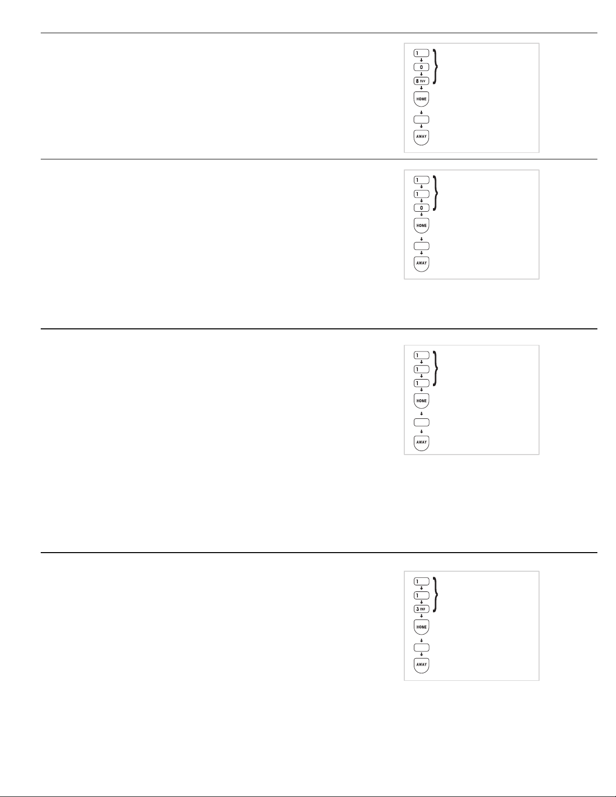
REPORT CONSOLE TROUBLE
The factory setting does not report Console
◆
trouble events to the Central Station.
Alternately, the communicator can be
◆
programmed to report Console trouble events.
These include all conditions that light the
Console’s BATTERIES or TROUBLE indicator. It
also includes low Console backup battery.
REPORT FORCE ARMING
The factory setting does not send force arming
◆
reports.
Alternately, the communicator can be
◆
programmed to report force arming anytime the
Console is armed with one or more bypassed
sensors.
The factory set reporting code for force arming is
◆
“65” (Code 574 with Ademco).
NOTE: If force arming is enabled, and the Console
✍
is force armed (armed with an open sensor)
remotely by telephone, or with the RA-2400
Remote Access software, the caller will be
disconnected if the communicator is enabled.
PROGRAMMING STEP #108
PROGRAM
0 FOR NO CONSOLE TROUBLE
1 FOR CONSOLE TROUBLE
STORE PROGRAM
PROGRAMMING STEP #110
PROGRAM
0 FOR NO FORCE ARMING RPTS.
1 FOR FORCE ARMING RPTS.
STORE PROGRAM
OPENING AND CLOSING REPORTS
The factory setting does not send opening and
◆
closing reports
Alternately, the communicator can be
◆
programmed to send an opening report when the
system is disarmed, and a closing report when
the system is armed for all users, or just the
master user.
NOTE 1: For commercial installations using
✍
opening and closing reports, it is recommended to
disable quick arming to prevent customers from
arming the system.
NOTE 2: The reporting codes are fixed for opening
✍
and closing. A unique code is reserved for the
master user code and each of the five restricted
user codes.
NOTE 3: Arming or disarming with the page alert
✍
user code dials the supervisory number, no
opening or closing report is sent.
POINT ID REPORTING
The factory setting enables Point ID and allows
◆
the communicator to send two-digit alarm and
trouble codes for each sensor. The individual
sensor that causes an alarm or trouble report can
be identified at the Central Station.
Alternately, Point ID can be disabled. The Central
◆
Station will only receive general alarm and
trouble reports.
PROGRAMMING STEP #111
PROGRAM
0 FOR NO OPEN/CLOSE REPORTS
1 FOR O/C RPTS. FOR ALL USERS
2 FOR O/C RPTS. FROM MASTER
USER ONLY
STORE PROGRAM
PROGRAMMING STEP #113
PROGRAM
0 FOR GENERAL REPORTS ONLY
1 FOR POINT ID REPORTING
STORE PROGRAM
37
Page 40

COMMUNICATOR REPORTING CODES
The two-digit communicator reporting code for
◆
each event has a factory set value. These values
may be customized to fit the specific installation
and the reporting requirements of the Central
Station monitoring the system.
If Point ID reporting is enabled (the factory
◆
default setting), each sensor can report a unique
alarm and trouble code.
If Point ID is disabled, the “general” reporting
◆
codes for each event type will be used.
Each programming function is performed with
◆
similar keystrokes. After the Console is in Setup
Mode, enter the programming step number,
press the [
the new value, and press the [
] key (HOME = program), enter
HOME
AWAY
] key
(AWAY = store).
Making a value 0 causes event to not
◆
communicate to central station.
NOTE: The reporting codes are fixed for opening
✍
and closing. A unique code is reserved for the
master and the five restricted user codes. See the
Opening & Closing Reporting Codes Table.
HOME
= PROGRAM
AWAY
= STORE
TEST
= REMOVE
GENERAL REPORTING CODES
Program Steps #201 - 206 for the communicator
◆
reporting codes when Point ID is disabled.
Refer to the Console & General Reporting Codes
◆
table to view/edit the reporting codes for each of
the five events. The factory settings are listed,
along with a blank area to write in the new
installation values.
Any value from 0-99 can be programmed for
◆
each event (0 = no report).
NOTE: Be careful not to duplicate codes unless
✍
the Central Station requires specific codes for
certain types of events.
SYSTEM REPORTING CODES
Program Steps #261 - 266 for the Console
◆
reporting codes.
Refer to the System Reporting Codes table to
◆
view/edit the reporting codes for the keypad
[EMERGENCY]
and
four Control Panel conditions. The factory settings
are listed, along with a blank area to write in the
new installation values.
[FIRE]
buttons and for each of the
ABC
2
PROGRAMMING STEPS
0
#201 TO #206
HOME
PROGRAM
0 - 99 FOR GENERAL
ALARM REPORTING CODE
AWAY
STORE PROGRAM
ABC
2
PROGRAMMING STEPS
MNO
6
#261 TO #266
HOME
PROGRAM
0 - 99 FOR SYSTEM
REPORTING CODE
AWAY
STORE PROGRAM
GENERAL REPORTING CODES
STEP #
201 GENERAL FIRE REPORT CODE 0 - 99 1
202 GENERAL EMERGENCY REPORT CODE 0 - 99 2
203 GENERAL SILENT PANIC REPORT CODE 0 - 99 3
204 GENERAL BURGLARY REPORT CODE 0 - 99 4
206 GENERAL TROUBLE REPORT CODE 0 - 99 6
PROGRAMMING
FUNCTION
POSSIBLE
VALUES
General Reporting Codes Table
38
FACTORY
VALUE
INSTALLATION
VALUE
Page 41
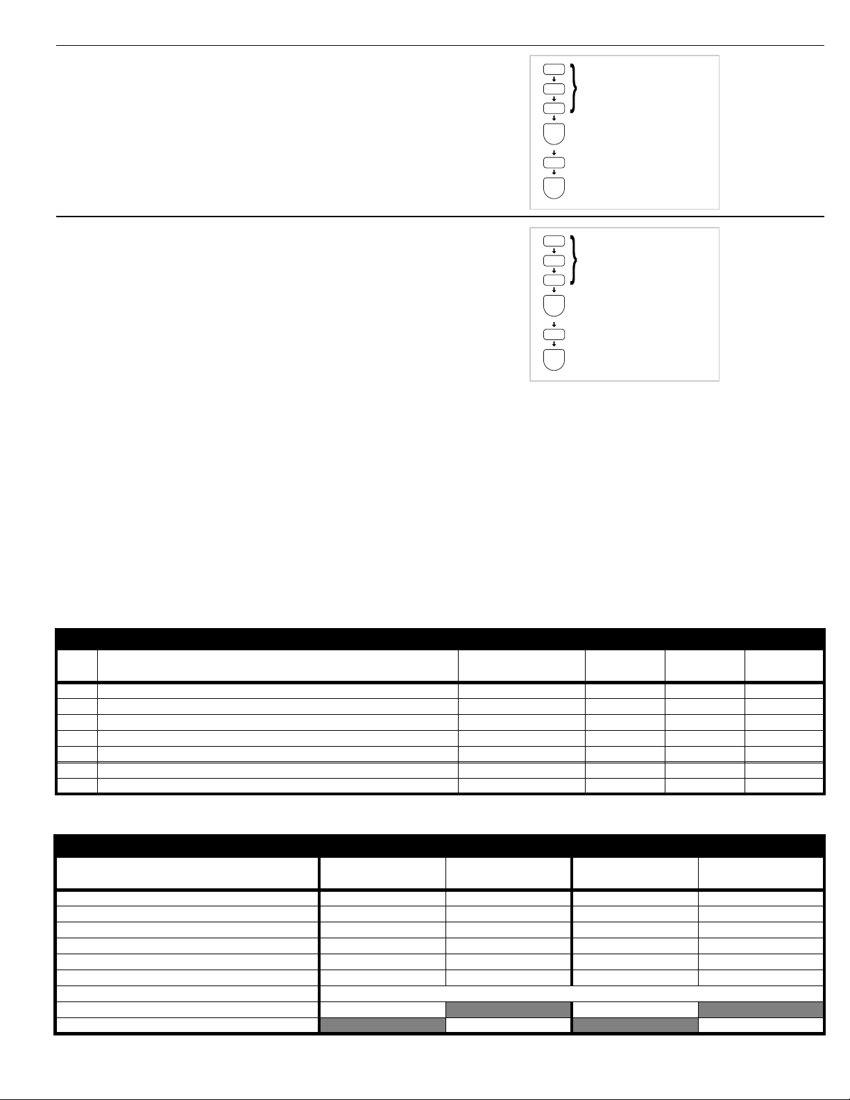
FORCE ARMING REPORTING CODE
Programming Step #258
◆
The factory set reporting code for force arming is
◆
“65” (Code 574 with Ademco).
Any value from 0-99 can be programmed for
◆
this event (0 = no report).
NOTE: For force arming reporting, force arming
✍
reports must be enabled. See Page 37.
ABC
2
JKL
5
PROGRAMMING STEP #258
TUV
8
HOME
PROGRAM
0 - 99 FOR FORCE ARMING
REPORTING CODE
AWAY
STORE PROGRAM
DURESS REPORTING CODE
Programming Step #259
◆
The factory set reporting code for Duress is “66”
◆
(Code 121 with Ademco).
Any value from 0-99 can be programmed for
◆
this event (0 = no report).
NOTE: For duress code reporting a keypad duress
✍
code must be programmed. See Page 30.
ABC
2
JKL
5
PROGRAMMING STEP #259
WXY
9
HOME
PROGRAM
0 - 99 FOR DURESS CODE
AWAY
STORE PROGRAM
SYSTEM REPORTING CODES
STEP #
261 SYSTEM FIRE REPORT CODE 0 - 99 68 110
262 SYSTEM EMERGENCY REPORT CODE 0 - 99 69 120
263 SYSTEM TEST/CANCEL REPORT CODE 0 - 99 70 406
264 SYSTEM LOW BATTERY RESTORAL REPORT CODE 0 - 99 71 R302
266 SYSTEM LOW BATTERY REPORT CODE 0 - 99 73 E302
258 FORCE ARMING REPORT CODE 0 - 99 65 574
259 DURESS REPORT CODE 0 - 99 66 121
PROGRAMMING
FUNCTION
POSSIBLE
4 x 2 VALUES
FACTORY
4 x 2 VALUE
ADEMCO
VALUE
INSTALLATION
4 x 2 VALUE
System Reporting Codes Table
OPENING & CLOSING REPORTING CODES TABLE
USER CODE
MASTER USER CODE 74 82 R401 C000 E401 C000
RESTRICTED USER CODE #1 75 83 R401 C001 E401 C001
RESTRICTED USER CODE #2 76 84 R401 C002 E401 C002
RESTRICTED USER CODE #3 77 85 R401 C003 E401 C003
RESTRICTED USER CODE #4 78 86 R401 C004 E401 C004
RESTRICTED USER CODE #5 79 87 R401 C005 E401 C005
PAGE ALERT USER CODE (DIALS PAGE NUMBER ONLY, NO CODES REPORTED)
REMOTE/HARDWIRE ARM (SENSOR TYPE 9) & QUICK ARM 81 R407 C007
REMOTE/HARDWIRE DISARM (SENSOR TYPE 9) 89 E407 C007
4 x 2 CLOSING
(ARMING) CODE
4 x 2 OPENING
(DISARMING) CODE
ADEMCO CLOSING
(ARMING) CODE
ADEMCO OPENING
(DISARMING) CODE
Opening & Closing Reporting Codes Table
39
Page 42

4 BY 2 FORMAT POINT ID REPORTING CODES
4 BY 2 FORMAT POINT ID ALARM REPORT CODES
Refer to the 4 by 2 Format Point ID Reporting
◆
Code table to view/edit the alarm reporting
codes for each of the 24 sensors. The
communicator will send these codes if Point ID is
enabled and any sensor triggers an alarm. The
factory settings are listed, along with a blank
area to write in the new installation values.
NOTE: Be careful not to duplicate codes unless
✍
the Central Station requires specific codes for
certain types of sensors.
Each programming function is performed with
◆
similar keystrokes. After the system is in Setup
Mode, enter the programming step number,
press the [
the new value, and press the [
] key (HOME = program), enter
HOME
AWAY
] key
(AWAY = store).
4 BY 2 FORMAT POINT ID TROUBLE REPORT CODES
Refer to the 4 by 2 Format Point ID Reporting
◆
Code table to view/edit the trouble reporting
codes for each of the 24 sensors. The
communicator will send these codes if Point ID is
enabled and any sensor has a low battery or
trouble condition. The factory settings are listed,
along with a blank area to write in the new
installation values.
NOTE: Be careful not to duplicate codes unless
✍
the Central Station requires specific codes for
certain types of sensors.
Each programming function is performed with
◆
similar keystrokes. After the Console is in Setup
Mode, enter the programming step number,
press the [
the new value, and press the [
] key (HOME = program), enter
HOME
AWAY
] key
(AWAY = store).
ABC
2
PROGRAMMING STEPS
#210 TO #233
HOME
PROGRAM
0 - 99 FOR SENSOR
ALARM CODE
(0 = NO REPORT)
AWAY
STORE PROGRAM
ABC
2
PROGRAMMING STEPS
#234 TO 257
HOME
PROGRAM
0 - 99 FOR SENSOR
TROUBLE CODE
(0 = NO REPORT)
AWAY
STORE PROGRAM
40
Page 43

POINT ID REPORTING CODES
STEP #
210 SENSOR 1 ALARM REPORT CODE 0 - 99 11
211 SENSOR 2 ALARM REPORT CODE 0 - 99 12
212 SENSOR 3 ALARM REPORT CODE 0 - 99 13
213 SENSOR 4 ALARM REPORT CODE 0 - 99 14
214 SENSOR 5 ALARM REPORT CODE 0 - 99 15
215 SENSOR 6 ALARM REPORT CODE 0 - 99 16
216 SENSOR 7 ALARM REPORT CODE 0 - 99 17
217 SENSOR 8 ALARM REPORT CODE 0 - 99 18
218 SENSOR 9 ALARM REPORT CODE 0 - 99 19
219 SENSOR 10 ALARM REPORT CODE 0 - 99 20
220 SENSOR 11 ALARM REPORT CODE 0 - 99 21
221 SENSOR 12 ALARM REPORT CODE 0 - 99 22
222 SENSOR 13 ALARM REPORT CODE 0 - 99 23
223 SENSOR 14 ALARM REPORT CODE 0 - 99 24
224 SENSOR 15 ALARM REPORT CODE 0 - 99 25
225 SENSOR 16 ALARM REPORT CODE 0 - 99 26
226 SENSOR 17 ALARM REPORT CODE 0 - 99 27
227 SENSOR 18 ALARM REPORT CODE 0 - 99 28
228 SENSOR 19 ALARM REPORT CODE 0 - 99 29
229 SENSOR 20 ALARM REPORT CODE 0 - 99 30
230 SENSOR 21 ALARM REPORT CODE 0 - 99 31
231 SENSOR 22 ALARM REPORT CODE 0 - 99 32
232 SENSOR 23 ALARM REPORT CODE 0 - 99 33
233 SENSOR 24 ALARM REPORT CODE 0 - 99 34
234 SENSOR 1 TROUBLE REPORT CODE 0 - 99 41
235 SENSOR 2 TROUBLE REPORT CODE 0 - 99 42
236 SENSOR 3 TROUBLE REPORT CODE 0 - 99 43
237 SENSOR 4 TROUBLE REPORT CODE 0 - 99 44
238 SENSOR 5 TROUBLE REPORT CODE 0 - 99 45
239 SENSOR 6 TROUBLE REPORT CODE 0 - 99 46
240 SENSOR 7 TROUBLE REPORT CODE 0 - 99 47
241 SENSOR 8 TROUBLE REPORT CODE 0 - 99 48
242 SENSOR 9 TROUBLE REPORT CODE 0 - 99 49
243 SENSOR 10 TROUBLE REPORT CODE 0 - 99 50
244 SENSOR 11 TROUBLE REPORT CODE 0 - 99 51
245 SENSOR 12 TROUBLE REPORT CODE 0 - 99 52
246 SENSOR 13 TROUBLE REPORT CODE 0 - 99 53
247 SENSOR 14 TROUBLE REPORT CODE 0 - 99 54
248 SENSOR 15 TROUBLE REPORT CODE 0 - 99 55
249 SENSOR 16 TROUBLE REPORT CODE 0 - 99 56
250 SENSOR 17 TROUBLE REPORT CODE 0 - 99 57
251 SENSOR 18 TROUBLE REPORT CODE 0 - 99 58
252 SENSOR 19 TROUBLE REPORT CODE 0 - 99 59
253 SENSOR 20 TROUBLE REPORT CODE 0 - 99 60
254 SENSOR 21 TROUBLE REPORT CODE 0 - 99 61
255 SENSOR 22 TROUBLE REPORT CODE 0 - 99 62
256 SENSOR 23 TROUBLE REPORT CODE 0 - 99 63
257 SENSOR 24 TROUBLE REPORT CODE 0 - 99 64
PROGRAMMING
FUNCTION
POSSIBLE
VALUES
FACTORY
VALUE
INSTALLATION
VALUE
Point ID Reporting Codes Table
41
Page 44

IMPORTANT INFORMATION
LINEAR LIMITED WARRANTY
This Linear product is warranted against defects in material and workmanship for
twelve (12) months. The Warranty Expiration Date is labeled on the product.
warranty extends only to wholesale customers
through Linear’s normal distribution channels.
product to consumers.
the nature of the dealer’s warranty, if any.
on the part of Linear Corporation for consequential damages arising out of
or in connection with use or performance of this product or other indirect
damages with respect to loss of property, revenue, or profit, or cost of
removal, installation, or reinstallation.
warranties for merchantability and implied warranties for fitness, are valid only until
Warranty Expiration Date as labeled on the product.
Warranty is in lieu of all other warranties express or implied.
For warranty service on Linear equipment return product, at sender’s expense to:
Linear Hong Kong
19/F Hounor Industrial Centre
6 Sun Yip Street
Chai Wan, Hong Kong
Attention: Repairs Department
Consumers should inquire from their selling dealer as to
who buy direct from Linear or
Linear does not warrant this
There are no obligations or liabilities
All implied warranties, including implied
This Linear Corporation
This
REPAIRS POLICY
Charges will be made for equipment that is not of warranty, shows
✶
customer abuse, or is damaged by the effects of lightning, water, fire, or
other abnormal happenings.
Customer’s equipment sent in for repair may be repaired or replaced with
✶
new or remanufactured equipment at Linear’s discretion.
The customer is always responsible for shipping and handling charges to
✶
the repairs facility. Linear will pay return shipping and handling charges
on “in warranty” products shipped back to the customer. The customer
will be billed for the return shipping and handling charges on “out of
warranty” products.
There will be a 50% expedite fee for any express requests.
✶
The International Sales Manager must be notified prior to the return of
✶
product to Linear. All international returns must have an International
Repair Authorization number (IRA#). The number must be marked on all
packages. Failure to do so will cause delays in processing.
IMPORTANT !!!
Linear radio controls provide a reliable communications link and fill an important
need in portable wireless signaling. However, there are some limitations which
must be observed.
The radios are required to comply with local rules and regulations as radio
✶
devices. As such, they have limited transmitter power and therefore limited
range.
A receiver cannot respond to more than one transmitted signal at a time
✶
and may be blocked by radio signals that occur on or near their operating
frequencies, regardless of code settings.
Changes or modifications to the device may void regulatory compliance.
✶
Infrequently used radio links should be tested regularly to protect against
✶
undetected interference or fault.
A general knowledge of radio and its vagaries should be gained prior to
✶
acting as a wholesale distributor or dealer, and these facts should be
communicated to the ultimate users
FCC NOTICE
This equipment generates and uses radio frequency energy and if not installed
and used properly, that is, in strict accordance with the manufacturer’s
instructions, may cause interference to radio and television reception. It has been
type tested and found to comply with the limits for a Class B computing device
in accordance with Part 15 of FCC Rules, which are designed to provide
reasonable protection against such interference in a residential installation.
However, there is no guarantee that interference will not occur in a particular
installation. If this equipment does cause interference to radio or television
reception, which can be determined by turning the equipment off and on, the
user is encouraged to try to correct the interference by one or more of the
following measures:
Relocate the Console away from the TV/radio receiver.
✶
Plug the Console into a different wall outlet so that the Console is on a
✶
different branch circuit.
Re-orient the TV/radio antenna.
✶
If necessary, the user should consult the dealer or an experienced
✶
radio/television technician for additional suggestions.
FCC TELEPHONE RULES AND REGULATIONS
The FCC requires that this alarm dialer system not make more than 15 repetitive
dialing attempts to a single telephone number. There are no limitations when
the calls are made sequentially to two or more alternative numbers, or when
these calls are spaced 10 minutes apart to a single number. The FCC Rules
and Regulations do not specify the re-attempt period as this can vary for specific
applications. When setting this period, take into consideration local, interstate,
foreign and special network call completion characteristics, network processing
time, a sufficient number of rings and busy/don’t answer modes
.
FIRE EVACUATION PLANNING
For systems that include fire protection, the following information should be
available to the users of the system.
Draw up a floor plan showing two exits for each room.
✶
The following procedures are to be discussed with the family:
Status of bedroom doors.
➀
Familiarity with alarm signals.
➁
Testing of door during a fire and use of alternate escape route if door is
➂
hot to touch.
Crawling and holding breath.
➃
Escape fast. No stopping for packing.
➄
Meet at designated outdoor spot.
➅
Emphasize that no one is to return to a burning house.
➆
Fire department notification from a neighbor’s phone.
➇
Periodic rehearsal is to be conducted.
➈
INDUSTRY CANADA NOTICES
: The ringer equivalence number (REN) assigned to each terminal
NOTICE
device provides an indication of the maximum number of terminals allowed to
be connected to a telephone interface. The termination on an interface may
consist of any combination of devices subject only to the requirement that the
sum of the ringer equivalence numbers of all the devices does not exceed 5.
: The Industry Canada label identifies certified equipment. This
NOTICE
certification means that the equipment meets certain telecommunications
network protective, operational and safety requirements. The Department does
not guarantee the equipment will operate to the user’s satisfaction.
Before installing this equipment, users should ensure that it is permissible to be
connected to the facilities of the local telecommunications company. The
equipment must also be installed using an acceptable method of connection.
The customer should be aware that compliance with the above conditions may
not prevent degradation of service in some situations.
Repairs to certified equipment should be made by an authorized Canadian
maintenance facility designated by the supplier. Any repairs or alterations made
by the user to this equipment, or equipment malfunctions, may give the
telecommunications company cause to request the user to disconnect the
equipment.
Users should ensure for their own protection that the electrical ground
connections of the power utility, telephone lines and internal metallic water pipe
system, if present, are connected together. This precaution may be particularly
important in rural areas.
CAUTION
should contact the appropriate electric inspection authority, or electrician, as
appropriate.
: Users should not attempt to make such connections themselves, but
Copyright © 2002 Linear Corporation 217157 B
 Loading...