

Page 1
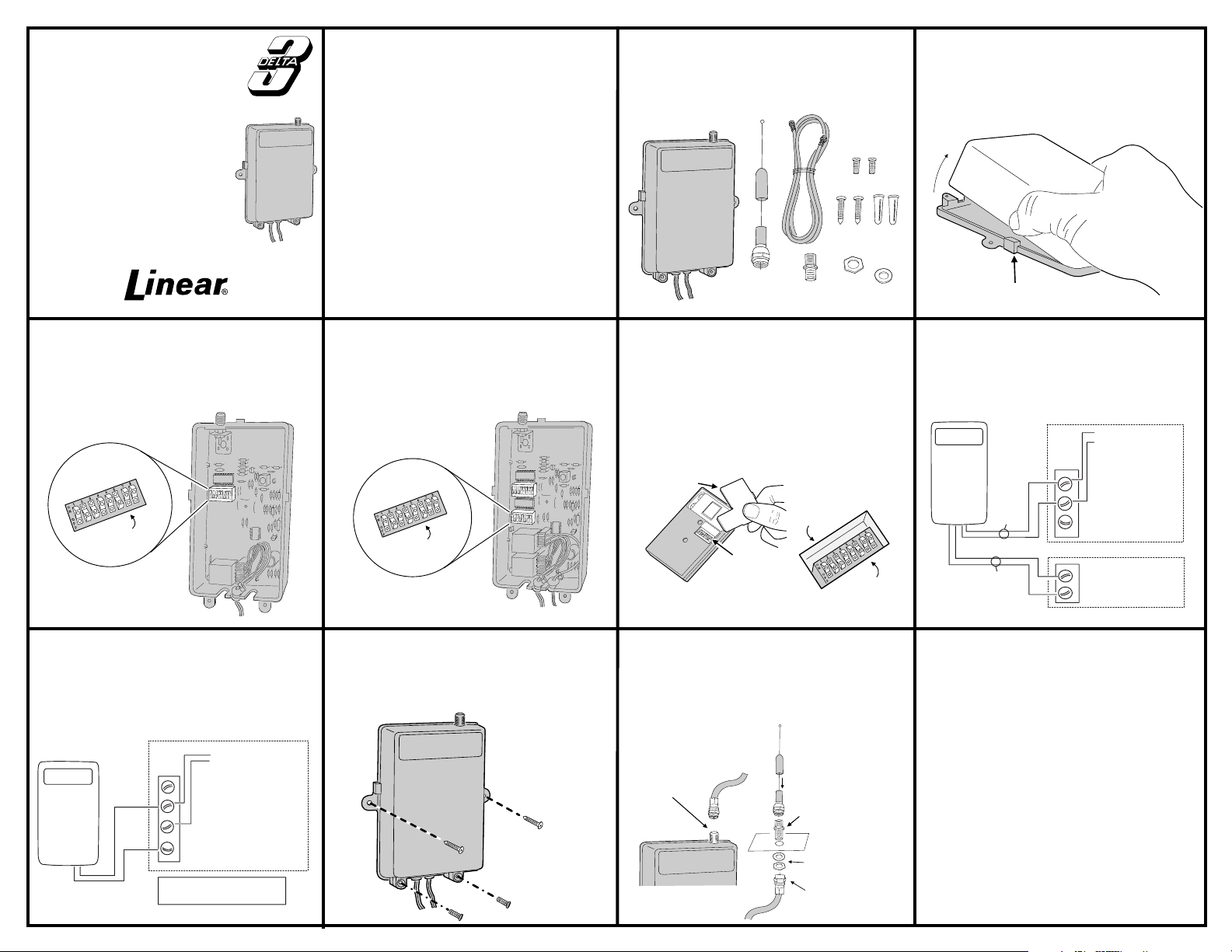
DRG-LV
SQUEEZE BOTH SIDES AT TABS
AND TILT UPWARD
DRG-2LV
DIGITAL
GATE
RECEIVER
Installation Instructions
(800) 421-1587 • www.linearcorp.com
DESCRIPTION
The DRG-LV is a digital receiver designed for use with
automatic gate operators or systems where a remote ante nna
is needed. The DRG-2LV will operate two gates, one gate and
an obstacle sensor or channel one can open the gate and
channel two can close the ga t e.
All of the Delta-3 transmitters, including the two and
four-channel transmitters, are compatible with the the DRG.
The Delta-3 radio format provides 256 different digital codes.
The codes are set using the 8-position coding switches in the
units. In order to avoid the possibility of duplicating codes in
adjacent systems, factory set codes should not be used.
The receivers can operate from 10.2-16 VDC or 12-16 VAC
and are normall y pow ered f rom th e gate oper ator . The relay
contact(s) are rated at 5 amps @ 30 volts AC/DC NEC Class
2 circuit.
The DRG has a “F” connector for attaching an antenna. The
receiver is supplied with a 9-inch local antenna, a three foot
75 ohm coaxial cable, and a bulkhead connector for
mounting the antenna outside the gate operator enclosure.
RECEIVER
LOCAL
ANTENNA BULKHEAD
CONNECTOR
3-FOOT
CABLE
CASE SCREWS
MOUNTING
HARDWARE
NUT
WASHER
STEP 1
Open receiver case.
To open case,
squeeze sides of case and rotate upward.
STEP 2A
DRG-LV code setting.
To set a
code, select any valid combination of ON and
OFF positions for the switch keys numbered 1- 8.
Use a paper clip to set the eight keys.
SET CODE
SWITCH KEYS
CHANNEL ONE
SWITCH KEYS
THIS SWITCH
HAS 2, 3 & 6 ON
DO NOT USE:
ALL ON; ALL OFF;
ALT ON/OFF, OR OFF/ON
STEP 5
Connect receiver to power.
Connect the red power input wire to the 12V radio
power and the black wire to the common terminal
on the gate operator. Alternately connect wires to
a 12-16 VAC transformer.
GATE OPERATOR
MANUAL
DRG
Digital Gate Receiver
BLACK
RED
INPUT VOLTAGE REQUIREMENT
10.2-16 VOLT DC or 12-16 VAC
ACCESS REQUEST
OBSTACLE
1
COMMON
2
RELAY
12 V RADIO POWER
3
STEP 2B
DRG-2LV code setting.
Select any
valid combination of ON and OFF positions for
each of the switch keys numbered 1 - 8.
Use a
different code combination than that used for
channel one switch.
SET CHANNEL TWO
CODE SWITCH KEYS
CHANNEL TWO
SWITCH KEYS
THIS SWITCH
HAS 2, 4 & 6 ON
DO NOT USE:
ALL ON; ALL OFF;
ALT ON/OFF, OR OFF/ON
STEP 6
Mounting the receiver.
Use the
screws provided to mount the receiver within the
operator housing. This provides protection from
the elements. Secure case with case screws.
MOUNT RECEIVER
INSIDE GATE
HOUSING
SECURE CASE
CLOSED WITH TWO
SCREWS AT BOTTOM
OF CASE
STEP 3
Transmitter code setting
. Locate
the coding switch on the transmitter and set the
eight keys identical to those on the desired
channel of the receiver.
If using a two or four-channel
exactly.
Be sure they match
transmitter, refer to the coding instructions
included with the transmitter for proper system
coding.
REMOVE BATTERY
ACCESS DOOR
SWITCHES IN
TRANSMITTER
CODING
STEP 7
SWITCH
Connect antenna.
THIS SWITCH
HAS 2, 3 & 6 ON
Connect the
coaxial cable to the “F” connector on the receiver.
Drill a 3/8" hole on the top of the operator housing
for the bulkhead connector. Insert the connector
and secure it with the nut and lock washer.
Connect the cable and antenna to the operator.
SLIDE WEATHER
RESISTANT CAP
CONNECT COAXIAL
CABLE TO "F"
CONNECTOR
OVER CONNECTION
INSERT BULKHEAD
CONNECTOR THROUGH
OPERATOR HOUSING
SECURE CONNECTOR
TO HOUSING USING
WASHER AND NUT
CONNECT CABLE TO
BULKHEAD CONNECTOR
STEP 4
Connect receiver relay output.
Connect the appropriate channel wires (Ch. 1 two gray wires), (Ch. 2 - two yellow wires) to the
appropriate activation terminals on the gate
operator.
GATE OPERATOR
DRG
Digital Gate Receiver
CHANNEL
ONE
GRAY
MANUAL ACCESS
REQUEST
1
COMMON
2
RELAY
3
12 V RADIO POWER
OBSTACLE INPUT
YELLOW
CHANNEL
TWO
This product is warranted to the consumer against defects in m aterial and workmanship
for one year from the date of purchase. This war ranty a pplies to f irst ret ail buyers of
new devices. Warrantor will repair, or at its option, replace, any device it finds that
requires service under this warranty, and will return the repaired or replaced device to
the consumer at the warrantor’s cost. For warranty service and shipping instructions
contact warrantor at t he ad dres s s hown below . D evice s must be sent to w ar ran tor for
service at owner’s ex pense. The remedies provi ded by this warranty are exclusive.
Implied warranti es un de r state law are to th e one year perio d of this written wa r r an ty.
Some states do not allow limitations on how long an implied warrant y lasts, so the above
limitation may not apply to you. In order to be protected by this warranty, save your
proof of purchase and send copy with equipment should repair be required. This
warranty gives you specific legal rights, and you may also hav e other rights which vary
from state to state.
All products returned for warranty service require a Return Product Authorization Number
(RPA#). Contact Linear Technical Services at 1-800-421-1587 for an RPA# and other
important detail s.
Linear radio controls provide a reliable communications link and fill an important need
in portable wireless signaling. However, there are some limitations which must be
observed.
For U.S. installations only: The radios are required to comply with FCC Rules and
✶
Regulations as Part 15 devices. As such, they have limited transmitter power and
therefore limite d range .
A receiver cannot resp ond to more than one trans mitted signal at a time and may be
✶
blocked by radio signals that occur on or near their operating frequencies, regardless of
code settings.
Changes or modific at io ns t o t he dev ice may void FCC c ompl ia nce.
✶
Infrequently u sed radio link s should be tes ted regularly to pro tect against undetected
✶
interference or fault.
A general knowledge of radio and its vagaries should be gained prior to acting as a
✶
wholesale distributor or d ealer, and these facts should be communicated to the ultimate
users.
Copyright © 1999 L ine ar Corporation 216267 B
LINEAR LIMITED WARRANTY
1
2
IMPORTANT !!!
COMMON
OBSTACLE
 Loading...