

Page 1
TRI-GARD 550/552LS SIGNATURE SERIES
The Signature Series™Tri-Gard is the first audio glassbreak
detector with microprocessor based,multiple signature
analysis. The detector filters amplitude components of sound
so that it can process all sounds at the same volume and
eliminate the need for sensitivity adjustments. This gives
maximum detection accuracy even in muffled (i.e.curtains,
shades,blinds,small glass sizes) glassbreak applications.
Through advanced signature analysis,common false alarm
sources are filtered out,while providing for the best
glassbreak detection.
TRI-GARD 550/552LS FEA TURES
• Specified for plate,wired, tempered & laminated glass
• Microprocessor-based for better discrimination
• Multiple SignatureAnalysis
• Signature Supervision
• Omnidirectional sensitivity
• No sensitivity adjustments
• Environmental switch feature
TRI-GARD 550/552LSAPPLICATIONS
• Glassbreak protection in residential,commercial
and industrial areas
• Protects plate,wired, tempered & laminated glass
• Omni direction detection to protect multiple windows
•Areas with closed drapes or blinds will reduce range.
T est with 515 tester for specific range
•Wall orceiling mount installations
SPECIFICATIONS
SENSING:Audio/air ,open space (enclosed area)
R
ANGE: The 550/552 is listed for plate, wired, tempered & laminated
glass. It is listed with drapes*, Blinds, curtains & sun film
T
HICKNESS: Plate
3
¼ 32" to1¼4"
Tempered–1¼ 8" to1¼4"
Wired–1¼ 4" Laminated–1¼ 4"
S
ENSING
FIELD: Omni-directional
S
ENSOR
: Electret condenser (F .E.T .pre-amp)
O
PERATING
VOLTAGE: 10–16 VDC filtered and regulated
P
OWER
CONSUMPTION:30 ma @13.6VDC normal.
O
PERATINGTEMPERATURE:14° to120° F . (-10° to 49° C)
R
ELAY
ACTIVATIONTIME: 3 seconds
A
LARM
LED: Latch or auto reset
A
LARM RELAY :SPDT (Form-C)- contacts .1Amp @30VAC/24VDC
T
AMPER CIRCUIT:Normally closed switch-contacts 50 milliamp s
@ 30V AC/24VDC.
V
OLTAGE M
ONITOR: Low or novoltage causesalarm
activation. Lowvoltage <10VDC causes red LED to flash slowly
I
NSTALLATION:Hardwire 6wires including 2 for tamper
T esting: Follow instructions & test once a year
MOUNTING: Surface– screw andanchors included
C
OLOR
:White or Cabin Brown
SIZE:3" x 3" x 3¼4"
TRI-GARD550/552LSSignature Series
™
AUDIO GLASSBREAK DETECTOR
GLASS CHART
T
ABLE 1
DIP Switch 1
position
ON
OFF
12" x 12"
or larger
12" x 12"
or larger
6" x 10"
to
12" x 12"
6" x 10"
to
12" x 12"
Glass size
Plate Tempered Wired Laminated
NOTE 1: The use of mini-blinds, shades, drapes* and sun film* can reduce the
range of the detector by 50%. Since room acoustics and window coverings can
vary considerably, all detector inst allations should be checked with the 515 tester.
* Not for sound deadening drapes
* Tested w/ 3M sun film #SH2CLAR (3M is a trademark of 3M Company)
30' 25' 25' 25'
30' 25' n/a
n/a n/a
n/a
15'
15'
550LS
552LS
(12"x12" minimum size)
(12"x12"
min size)
®
,
Page 2
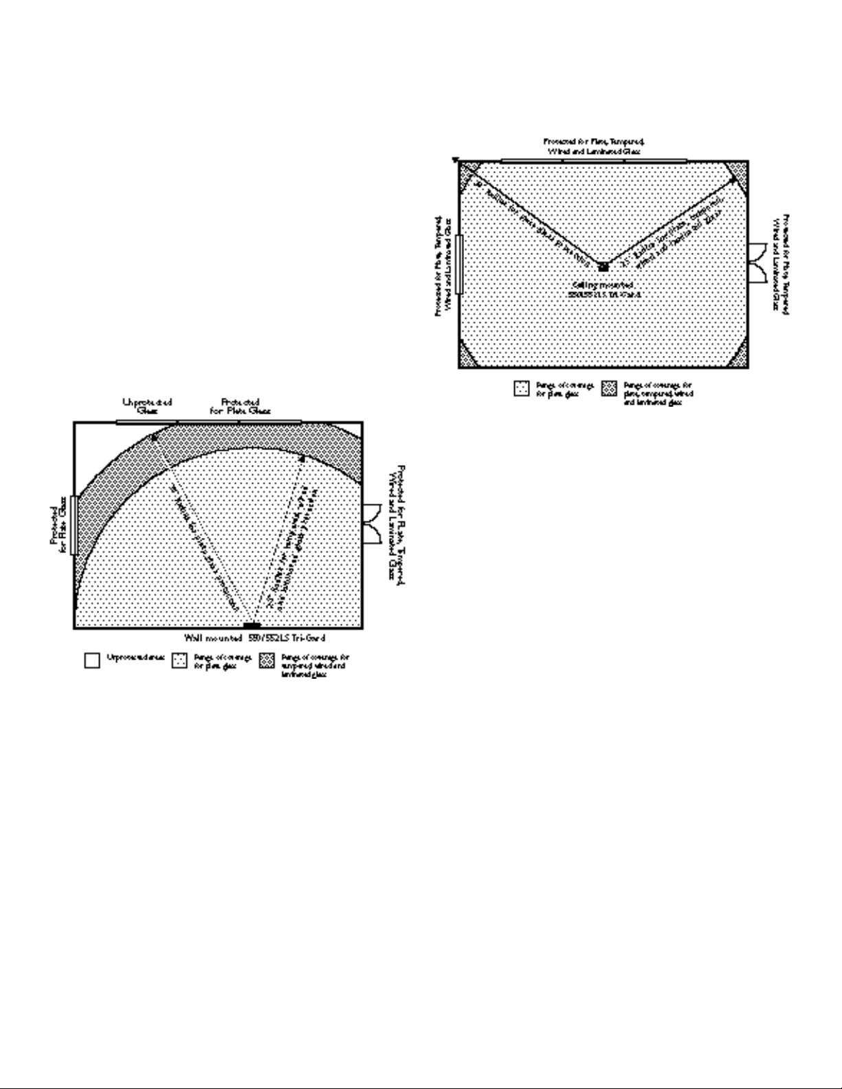
MOUNTING LOCATIONS
The Tri-Gard can be mounted on any type of ceiling or wall.
For best false alarm immunity the detector should be mounted at least 4’ from the glass to be protected and from noise
sources such as kitchen sinks,stereos,television,etc.For
maximum performance install the detector in direct line of
sight to all glass that you are protecting.
WALL MOUNTING
Mount the 550/552LS on an opposite or adjacent wall from
the glass to be protected.
The detector should be no closer than 4 feet from the glass to
be protected.Since the sound waves of breaking glass travel
directionally out from the broken window the best mounting
location is on the opposite wall,assuming the wall is within
detection range.
NOTE:The unit should not be mounted on the same wall as
the glass to be protected.
CEILING MOUNTING
Mount the 550/552LS in any location on the ceiling which is
in direct line of sight of the glass to be protected.Mount the
550LS on any solid material.
550/552LS OPERATIONS AND WIRING
On power-up the microprocessor will momentarily turn on
each LED. If Signature Supervision is selected, the amber
LED will latch until reset (see signature supervision).
LEDs
• Green LED ON–solid indicates unit is properly powered.
• Green LED OFF–indicates that the relay has dropped out,
due
to the detector being tripped or no/low power (<10VDC).
• Green LED FLASHES–slowly to indicate that the unit is in
test mode (see test mode).
•Amber LED FLASHES–when there are background noises
present within the detection range.
•Amber LED ON– solid indicates that the “Signature
Supervision” has not been able to test all circuits within the
last120 hours.
• Red LED ON–solid indicates that the detector has been
tripped and is in a latched alarm memory condition.
• Red LED FLASHES–to indicate that there is an alarm for
low power condition, input voltage is (<10VDC).
Page 3

I
NSTALLATION OPTIONS
DIP SWITCH 1– (Environmental Switch) (Laminated
glass/commercial applications)
ENVIRONMENT AL
SWITCH MODE (SEE TABLE 1)
For laminated glass and commercial and industrial applications,
put DIP switch 1 in the ON POSITION. Often replacement glass
for commercial and industrial applications will be laminated glass.
For most residential applications, keep DIP switch 1 in the OFF
POSITION.
DIP SWITCH 2– (Alarm LED Latch Mode)
• OFF–Red LED lights for 3 seconds on alarm and then turns off.
• ON– Red LED will latch in memory upon an alarm.Interrupt
power or turn off & on dip switch 2 to reset.
DIP SWITCH 3– (Signature Supervision)
• OFF– Normal operation- without “Signature Supervision”.
• ON– Enables “Signature Supervision” processing.
SIGNA TURE SUPERVISION
™
Using a microprocessor enables the detector to process more
data to make better decisions in determining a glass break event
and also provide more information back to the user regarding the
operating status of the device. A glass break event occurs over a
broad frequency range. There are frequencies present from10 to
10,000 cycles during a glass break event.Signature Supervision
monitors the input from the microphone and the associated circuitry to insure that the unit continues to “hear” across the frequency
spectrum.If,after120 hours (5 days),the sensor has not heard the
individual frequency elements associated with the signature frequencies within glass break the amber LED will come on and stay
latched to indicate a potential trouble situation (NOTE: this does
not trip the alarm relay).When the detector has heard those particular frequencies associated with glass break,the amber LED will
reset.Clapping,for example,will often produce the range of
frequencies that are present in glass break and can be used to
reset the unit.Notice that while clapping will reset the Signature
Supervision,it will not cause an alarm because it does not meet
other criteria that the microprocessor is using to determine a true
glass break event.This feature is dip switch selectable.
NOTE: If the amber LED is lit and is unable be to reset by
clapping,the customer should contact the installing dealer .
MOMENT ARY TEST SWITCH– (Test Mode)
•T est mode is disabled upon power up,but may be enabled by
momentarily depressing the test switch.
TESTMODE
T est mode allows the installer to properly test theTri-Gard with the
IEI 515 G
LASS BREAK SIMULATOR.Upon power up the unit will be in
normal operating glass break mode indicated by solid green LED.
T o enable the test mode momentarily depress the test switch. This
will start the green LED flashing slowly . Y ou now have two minutes
to test the detector.Every time you trip the detector,indicated by
the green LED turning off and the red LED turning on for four seconds,you will re-start the two minute test time (NOTE:the red LED
will not latch during test mode even if you have DIP switch 2 alarm
memory on).If you do not trip the detector within the two minutes
test period then the detector will return to normal glass break
mode,indicated by the solid green LED. To immediately return to
normal glass break mode after the detector is tested correctly ,simply interrupt power for one second.
NOTE:T est mode does not prevent the 550/552LS from detecting
breaking glass.
550LS
CIRCUIT
BOARD
552LS
CIRCUIT
BOARD
NOTE: Tamper spring is in hardware package with screws
Page 4

THIS DEVICE COMPLIESWITH PART15 OF THE FCC RULES.OPERATION IS
SUBJECT TOTHE FOLLOWINGTWO CONDITIONS: (1) THIS DEVICE MAYNOT
CAUSE HARMFULINTERFERENCE,AND (2)THIS DEVICE MUSTACCEPTANY
INTERFERENCE RECEIVED,INCLUDING INTERFERENCE THATMAYCAUSE
UNDESIRED OPERATION.
WARNING: Changes or modifications to this unit not expressly approved by the party responsible for compliance could
void the user’s authority to operate the equipment.
NOTE:This equipment has been tested and found to comply with the limits for a Class B digital device,pursuant to Part
15 of the FCC Rules. These limits are designed to provide reasonable protection against harmful interference in a residential installation. This equipment generates,uses and can radiate radio frequency energy and, if not installed and used
in
accordance with the instructions,may cause harmful interference to radio communications.However, there is no guarantee that interference will not occur in a particular installation.
If this equipment does cause harmful interference to radio or television reception,which can be determined by turning the
equipment off and on,the user is encouraged to try to correct the interference by one or more of the following measures:
• Re-orient or relocate the receiving antenna
• Increase the separation between the equipment and the receiver
• Connect the equipment into an outlet on a circuit different
from that to which the receiver is connected
• Consult the dealer or an experienced radio/TV
technician for help
IEI LimitedWarranty:
Because the manufacturer does not install or connect this security device the manufacturer cannot guarantee its performance. Therefore,there are no warranties,
expressed or implied (except as stated below),attached to the sale or use of this product.
The manufacturer warrants against defects in material and workmanship in this device
for 3 years from the date of manufacture.During the warranty period the
manufacturer,at its sole option,will repair or replace free of charge any defective unit
returned freight prepaid. This warranty shall remain in force and effect for 3 years provided the unit was properly installed and operated,has not been subject to misuse and
has not been repaired or altered other than by the original manufacturer.
The foregoing states the buyer's sole and exclusive remedy for any breach of warranty
or for any claim,whether sounding in contract, tort,strict liability,or negligence, based
upon any defect in this security device.
The manufacturer shall in no event be responsible for any incidental or consequential
damages incurred by the buyer.
This warranty supercedes all previous warranties.
PRE-TESTING THE TRI-GARD 550/552LS
FOR DESIRED LOCATION
Pre-testing of the detector prior to final installation can be
performed to ensure that the detector is installed in the proper
location with respect to all glass being protected. The IEI 515
Glass Break Simulator is required to perform this test.
WARNING:
The 550/552LS detector has been designed to detect glass break
within a specified range from the glass–(30' for plate glass and 25'
for tempered,laminated and wired glass). You should not extend
past these rated ranges for any reason. Acoustics of different
areas can artificially extend the range of the 515 tester.
1) Before you test the unit in the desired location,close all
curtains,drapes and blinds to ensure that the detector will be
tested for worst case environmental conditions.
2) Remove the cover from theTri-Gard
3) Connect a 9V olt DC alkaline battery .
NOTE: the red LED will flash slowly indicating low voltage (input
voltage <10VDC) and also the relay will not be energized (common and normally closed will be open). These battery clips are
available at Radio Shack Part # 270-325
4) Momentarily depress the test switch to enable test mode.
NOTE: the green LED will flash while in test mode.
5) Replace the cover
6) Set the 515 tester in auto mode and place it near the window
that you are protecting.Place tester behind any curtains,drapes or
blinds.NOTE: the 515 will trip every 8 seconds in auto mode.
7) Position the unit in the desired mounting location and hold in
place and observe the following response:
If the green LED goes out and the red LED turns on for three
seconds then the glass is within range. Note:T est several times
with the 515 tester to ensure consistent detection. If the green
LED continues to flash then the detector is out of range and should
be reposi-tioned closer to the glass being protected.If the
550/552LS still does not trip then it is possible that the battery
being used for the detector is low and should be replaced or the
515 battery is low and should be replaced.
CAUTIONS
• T o improve false alarm rejection do not use for 24 hour applications in occupied areas, areas where white noise, such as air
compressors or machinery may be present or within 4 feet of
the glass being protected.
• Performance of any audio detection device depends upon an
audible signal and may be compromised when detecting
glassbreak if little or no sound is generated. For example, avoid
installations with sound insulating window coverings.
• T o learn more about detecting glass break, call IEI at
1-800-343-9502 for further information on audio detectors
and other devices that provide glassbreak detection.
427 TURNPIKE STREET, CANTON, MA 02021 U.S.A.
800-343-9502 OR IN MA 800-733-9502
www.ieib.com
®
,
 Loading...