

Page 1
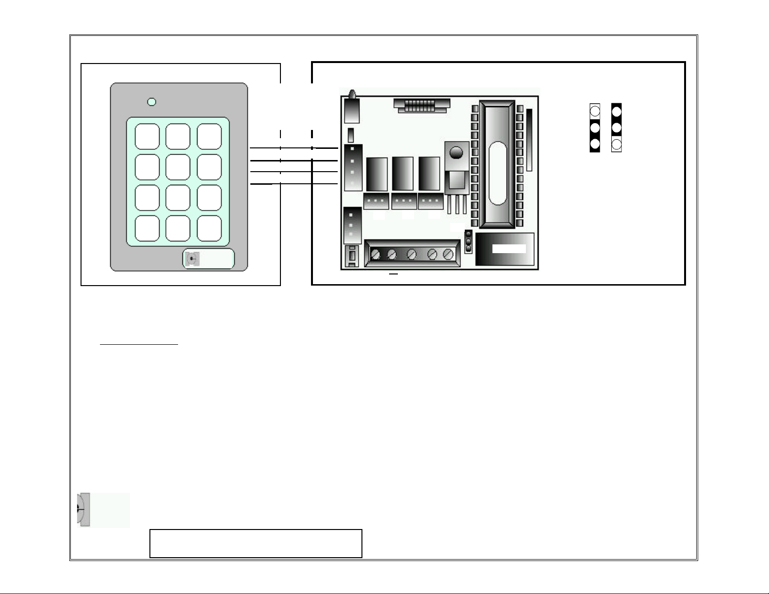
212xt Wiring Diagrams and Specifications
Wire Xtreme Pad
to Appropriate color
wires on Programmer
(Red to Red, etc.)
1
2
4 5 6
3
( White / Yellow )
( White / Black )
( Red )
( Black )
Voltage Selection Settings
P5*
Position
2
12-24VAC
15-24VDC
Position
1
12-15VDC
7 8
0
9
#
P1
*
SW1
*P5 is the Voltage Selector. With the jumper in position one, 12-15vdc only operation is
selected. With the jumper in position two 15-24vdc/12-24vac operation is selected.
Packing Checklist:
Xtreme™ Keypad
212 XT Programming Controller
Four Conductor Wire Harness (1)
Three Conductor Wire Harness (4)
Slotted Screws (4)
Plastic Anchors (4)
Machine Screws (2)
5/64 Allen Head Wrench (1)
Tech Supp. With Warranty card
Command & Control Features and Programming Guide
INTERNATIONAL
ELECTRONICS, INC
INTERNATIONAL ELECTRONICS, INC.
427TURNPIKE STREET, CANTON,MA 02021 U.S.A.
800-343-9502, 617-821-5566 (FAX)617-821-4443
TM
Visit our website for Access Control & Glassbreak information,
New Products, Specifications, Applications, Seminars, and Partners
@ WWW.IEIB.COM
P2
+
P3
NC C
P4
P5*
RELAY
NO
P1-REX INPUT
P2-RELAY 2
P3-RELAY 3
P4-RELAY 4
P5-VOLTAGE SELECTOR
SW1-PROGRAMMING SWITCH
SPECIFICATIONS:
MECHANICAL:
XT CASE DIMENSIONS:
2.75”w x 4.50”h x 1.50”d
PROGRAMMER CASE DEMENSIONS:
2.75”w x 4.50”h x 2.50”d
ELECTRICAL:
VOLTAGE:
12-24 Volts AC/DC (selected by jumper)
CURRENT:
@12-24 Volts AC/DC- 20ma typical-150 max with all relays
energized
OUTPUTS:
Main relay: 8 Amp, Form-C @ 24volts-10 AMP surge
Relays 2, 3, & 4 are Form C relays-1 AMP MAXIMUM
ENVIRONMENTAL:
TEMPERATURE:
-20°F TO 130°F (-28°C TO 54°C)
6061170 REV 1.01
Page 2
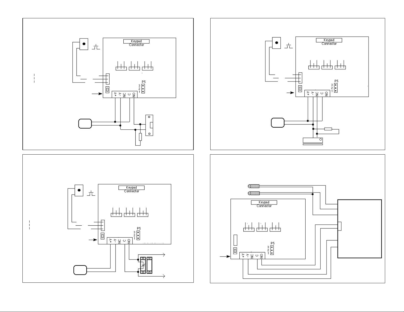
Basic Access Control with an Magnetic LockBasic Access Control with an Electric Door Strike
Remote Triggering Input
Not Used
Remote Triggering Input
12 or 24 volt AC/DC
power supply
Note: Lock voltage must
match power supply voltage
Remote Triggering Input
Not Used
Remote Triggering Input
12 or 24 volt AC/DC
power supply
Normally Open
Remote Switch
White/Orange
Brown
Programming
Switch
White
NO NC
OUTPUT
SW1
Shunting an Alarm Zone
Normally Open
Remote Switch
White/Orange
Brown
Programming
Switch
White
SW1
NO NC
C
OUTPUT
2
TS 1
NO NC
C
C
OUTPUT3OUTPUT
2
TS 1
Transorb
NO NC
C
OUTPUT3OUTPUT
NO NC
C
4
-Jumper on 2&3 for
12-15 VDC only
-Jumper on 1&2 for
15-24 VDC
12-24 VAC
Electric door strike
( Fail secure )
NO NC
C
4
-Jumper on 2&3 for
12-15 VDC only
-Jumper on 1&2 for
15-24 VDC
12-24 VAC
To Alarm Panel
Closed Circuit
Loop
Green LED
( panel disarmed )
( panel armed )
Programming
Switch
Normally Open
Remote Triggering Input
Not Used
Remote Triggering Input
12 or 24 volt AC/DC
power supply
Note: Lock voltage must
match power supply voltage
Remote Switch
White/Orange
White
Brown
Programming
Switch
Magnetic Doorlock
( Fail Safe )
SW1
NO NC
C
OUTPUT
2
TS 1
NO NC
NO NC
C
C
OUTPUT3OUTPUT
4
-Jumper on 2&3 for
12-15 VDC only
-Jumper on 1&2 for
Transorb
15-24 VDC
12-24 VAC
Arming and Disarming a typical Alarm Control Panel
NOTE: LED’s not provided with Keypad.
Connections are shown for a typical panel with
sink outputs.
Red LED
SW1
NO NC
C
OUTPUT
2
TS 1
NO NC
NO NC
C
C
OUTPUT3OUTPUT
4
-Jumper on 2&3 for
12-15 VDC only
-Jumper on 1&2 for
15-24 VDC
12-24 VAC
TYPICAL ALARM
CONTROL PANEL
GREEN LED (-)
RED LED (-)
12 VOLTS (+)
ARM/DISARM
TERMINALS
12 VOLTS (-)
12 VOLTS (+)
6061170 REV 1.01
Page 3

Auxiliary Outputs
The Extreme™ programming controller comes equipped with 3 auxiliary relay outputs and 3 internal timer circuits. The outputs can operate from 01-90 seconds, or you can program them to latch in
the energized position until the same code, or another latch code is entered. These outputs maybe
used to turn on or off, or shunt most devices after a valid code entry. The relays are form C relay
and are rated to handle one (1) amp of current at either 12 volts or 24 volts, type AC or DC.
To incorporate this feature into your system, simply locate one of the five connectors, each one with
three (3) wires, green, blue, and gray, located in the box with the XtremeTMprogramming controller.
With the controller powered down, unlatch the keypad from the plastic housing and slide the printed
circuit board out of housing. With the circuit board out, you may now choose one of the exposed
outputs as shown in Diagram A.
Wiring the Auxiliary Relays
Example: to a sounder
1. Connect the three conductor harness with the green,
blue, and gray wire to the auxiliary output relay jack as
shown in diagram A.
2. Connect green wire to V+ on sounder.
3. Connect blue wire to V+ from power supply.
4. Connect V- from power supply to V- on sounder.
5. Gray wire is not used.
XtremeTMCONTROL RELAY BOARD
DIAGRAM A
Propped
Door
Relay
Programming the Auxiliary Outputs
To program how long the output can operate for, Program
as follows:
1. Enter programming mode. Press 99 # (master code) *
Verify controller is in programming. Yellow light should
be flashing slowly.
2. Select the output that you want to program.
For output #2, press 12# (relay time)# 0# * *
For output #3, press 13# (relay time)# 0# **
For output #4, press 14# (relay time)# 0# * *
* Relay time must always be represented by
two digits. for 5 seconds (05).
To operate selected output(s) with a user code.
3. Verify that you are still in programming mode.
4. Press 59# (The output you choose: ie 2) #
(user number) # (new code) * (repeat code) *
5. Exit programming mode by pressing the *
user number is where your code is stored in the memory of
the keypad.
door contact
V+
white wire
with orange
stripe
white wire
GREEN (NO)
V-
GRAY (NC) NOT USED
BLUE (C)
V+
To
Power Supply
DIAGRAM B.
 Loading...