

Page 1
212w Wiring Diagrams and Specifications
TECHNICAL NOTES
This product was re-designed using a new
manufacturing technology, which changed the
physical appearance of the keypad electronics. Also,
the voltage selection jumper on the main circuit board
is no longer required.
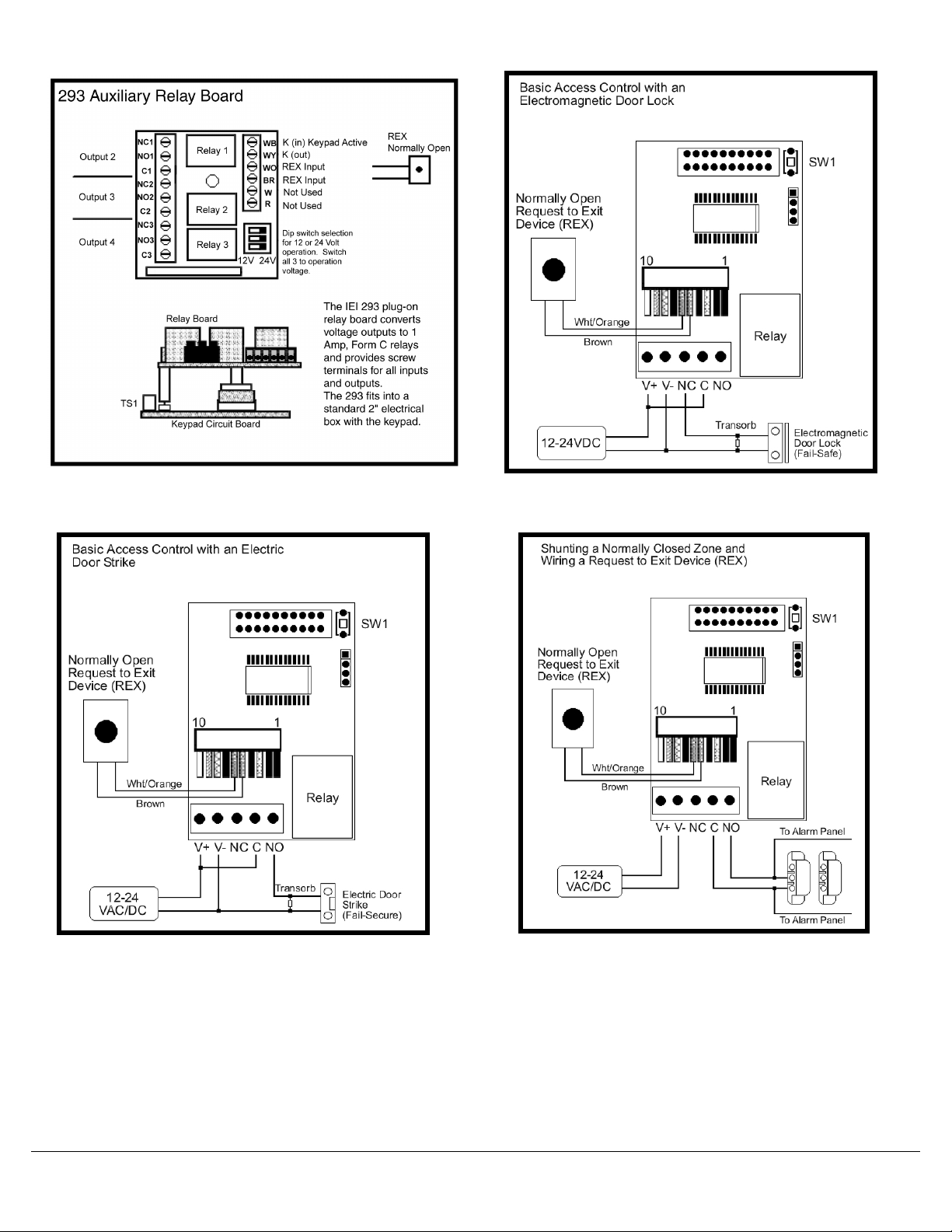
To prevent electrical kick back voltage from damaging the
keypad, when using an electrical locking device, you
MUST install the transorb as close as possible to the lock.
Wire the transorb in parallel with the lock power terminals.
Also, to avoid ESD (electro-static discharge) from
interfering with the operation of the keypad, ground the
negative terminal of the keypad to earth ground. If you
cannot ground the power supply, then you must ground
the keypad housing.
IEI recommends using a filtered and regulated power
supply
When mounting the 212w outside, use a weatherproof
back box and apply silicone to the area where the wires
enter the case. Also, provide a weep hole at the bottom
of the back box to prevent condensation from collecting
on the circuit board. This keypad is not for use in extreme
weather conditions; please consult the factory for
additional keypad models
6041222 Rev 1.0
SPECIFICATIONS:
MECHANICAL:
BOARD DIMENSIONS: 1.80”W x 2.555”H x 1.125”D
ELECTRICAL:
VOLTAGE: 12-24 Volts AC/DC (No Jumper Required)
CURRENT: 8mA@12VDC typical;
35ma with relay energized.
16mA@24VDC typical;
45ma with relay energized.
21mA@12VAC typical;
74mA with relay energized.
43mA@24VAC typical;
91mA with relay energized.
Note: Keypads using the 293 Relay Board,
need an additional 30mA for each
relay energized.
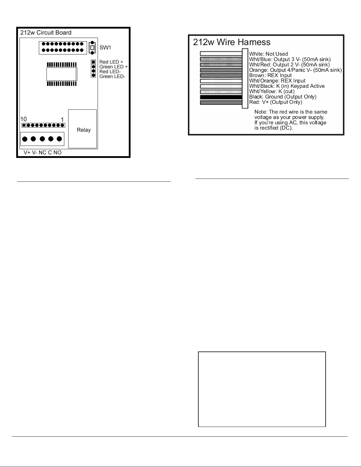
OUTPUTS: Main Relay: 5 Amp, Form C @ 24VDC
with 10 Amp surge.
Outputs 2, 3, and 4 are 50mA negative
voltage outputs
ENVIRONMENTAL:
TEMPERATURE: -20°F TO 130°F (-28°C TO 54°C)
Weather Resistant
Packing Checklist
212w Keypad
10 Conductor Wire Harness (1)
4 Conductor Wire Harness (1)
Slotted screws (2)
Security Screws (2)
Transorb (1)
Mounting Gasket (1)
Features & Programming Guide
Warranty Guide
1
Page 2
2
6041222 Rev 1.0
Page 3

To control the LED’s externally cut the four
wires going to the green and red LEDs. Each
LED has a black and red wire. Black is the
negative and red is the positive. These LED’s
require 12VDC to operate.
6041222 Rev 1.0
3
Page 4

p
INTERNATIONAL ELECTRONICS, INC.
427 TURNPIKE STREET
CANTON, MA 02021 USA
800-343-9502, 781-821-5566,
781-821-4443 (FAX)
WEB ADDRESS: www.ieib.com
The diagram above shows how to connect
two keypads to control a single door.
Entering your code on keypad 2 unlocks the
maglock directly. When you enter your code
on keypad 1, it triggers the REX input of
keypad two, which unlocks the door.
Please note that user codes must be
rogrammed into both keypads.
4
6041222 Rev 1.0
 Loading...