

Page 1

IEI PowerKey AC
®
USA & Canada (800) 421-1587 & (800) 392-0123
(760) 438-7000 - Toll Free FAX (800) 468-1340
www.linearcorp.com
GENERAL SPECIFICATION: The IEI PowerKey AC 110v Machinery Access Control System is an indoor unit designed
to limit access to power devices only to authorized users. Up to 99 users may be programmed with a 1-6 digit code. The
PowerKey AC 110V is wired for 110 VAC devices only. Both sensed and unsensed switching is available. This will allow, for
example, wiring both a saw (sensed) and a blower (unsensed) to the PowerKey AC. The saw and the blower will turn on
simultaneously when a valid code is entered. The saw may be started and stopped over and over again using the trigger
or switch on the saw. Each time the saw is turned off the PowerKey AC will sense that the device is not being used and
an Auto Shut-Off Timer will start. If the saw is started once again the timer will reset. If the saw is not used again and the
timer runs out, the PowerKey AC will turn off power to both the saw and blower. To again allow power to the saw and to
start the blower, re-enter a valid code.
POWER RATINGS: The PowerKey AC can control a maximum of 20 AMPS or up to a 1 ½ HP motor. Exceeding these
ratings will cause permanent damage to the PowerKey AC. The current sensor within the device can detect loads over
.150 amps and up to 20 amps. If the PowerKey AC senses more than 20 amps through the red wire (due to a possible
overload of the motor), the unit will automatically shut down and the red and green LED’s will fl ash alternately indicating
an overload condition.
WEATHER RATING: The PowerKey AC is for indoor use only and should not be mounted outdoors.
TEMPERATURE RANGE: -20°F to 130°F, -28°C to 54°C
AUTO SHUT-OFF TIMER: When a proper code followed by the * key is entered, the power will be turned on to both the
sensed and unsensed device(s). Power will stay on as long as the sensed device is being used. After the sensed device is
turned off, the PowerKey AC senses the device is no longer drawing power (not being used) and the Auto Shut-Off Timer
starts. As a warning that the timer is about to run out, the PowerKey AC will fl ash green for the last 10 seconds of the
timer. After the timer completely elapses (programmable from10-990 seconds), the PowerKey AC will turn off the power to
the controlled device(s). A valid code must be entered to turn power on again. Power to the controlled device is on when
the green LED is on solid or fl ashing. Power may also be turned off manually by pressing and holding any key for ½ a
second.
Machinery Access Control System
Model 110v
LOCKOUT CODE: If there is some reason for which you do not want to let anyone operate the machinery being
controlled, (such as a worn belt which needs replacing for example), you can enter a “LOCKOUT” code, which will disable
all “NORMAL” user codes from operating the machinery. A fl ashing red LED will indicate this “LOCKOUT” condition. Enter
a “LOCKOUT” code again to release the PowerKey AC from this condition.
INSTALLATION STEPS: The PowerKey AC unit should ONLY be installed by a licensed electrician.
1. Mount the PowerKey AC in an indoor location convenient to the device to be controlled.
2. Check the power rating of each device to be controlled. The total power of both the sensed or unsensed devices
should not exceed 20 amps or 1 ½ horsepower.
3. Running a 110v line wiring coming to the PowerKey AC from the breaker panel is recommended.
4. Remove the outer cover of the PowerKey AC by removing the 4 screws of the cover. This will reveal access to the
wiring compartment of the PowerKey AC.
IMPORTANT: Access to the electronics is not necessary for installation. Removal of the inside cover will void
the warranty!
5. Connect (Hot) 110 VAC line wiring to black wire of PowerKey AC and to one red wire for sensed load. Also connect
Hot of 110VAC to one blue wire if needed for the auxiliary unsensed load (e.g. a vacuum system).
6. Connect (Neutral) 110 VAC line wiring to the white wire of the PowerKey AC and to the neutral load wire(s) coming
from the controlled equipment.
7. Connect the load wire from the device to be controlled to the other red wire. Connect the load wire from the
auxiliary device to the other blue wire.
8. IMPORTANT: Connect the Ground to the lug inside the wiring compartment.
Page 1
Page 2
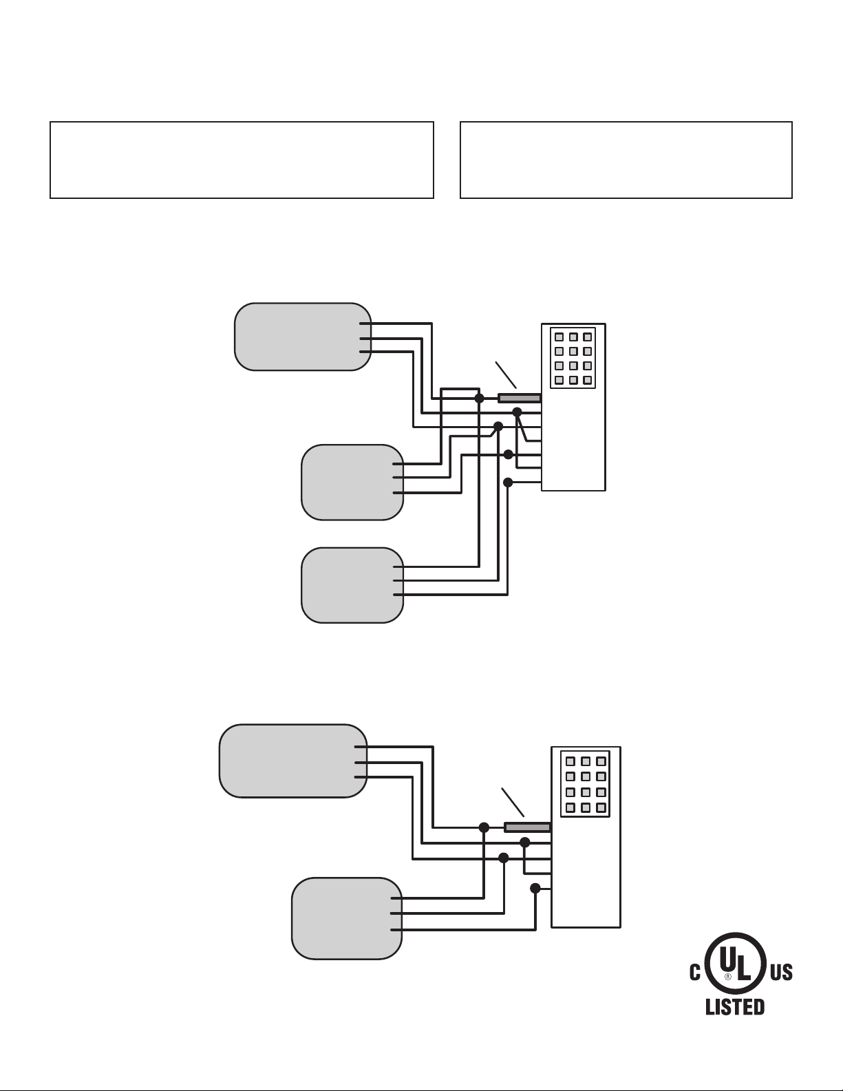
❏ 110 VAC POWER INPUT:
Black & White
Control Relay wiring:
Red Line 1 Sensed
Red Load 1 Use this wire for the controlled machinery
Example: a radial arm saw
This load is monitored.
B r e a k e r P a n e l
G R O U N D
H O T ( 1 1 0 V A C )
N E U T R A L ( 1 1 0 V A C )
C o n t r o l l e d L o a d 1
G R O U N D
L I N E 1
L O A D 1
( S E N S E D )
Blue Line 2 Unsensed
Blue Load 2 Use this power for auxiliary
Example: a sawdust vacuum system
This load is NOT monitored.
P o w e r K e y A C
G R O U N D L U G
G r o u n d L u g
B l a c k
W h i t e
R e d
R e d
B l u e
B l u e
C o n t r o l l e d L o a d 2
G R O U N D
L I N E 2
L O A D 2
( U N S E N S E D )
Wiring Diagram for PowerKey with an Auxiliary Device
B r e a k e r P a n e l
G R O U N D
H O T ( 1 1 0 V A C )
N E U T R A L ( 1 1 0 V A C )
C o n t r o l l e d L o a d 1
( S E N S E D )
G R O U N D L U G
G R O U N D
L I N E 1
L O A D 1
P o w e r K e y A C
G r o u n d L u g
B l a c k
W h i t e
R e d
R e d
B l u e
B l u e
Wiring Diagram for PowerKey without an Auxiliary Device
Page 2
Page 3

IEI PowerKey AC Programming Guide
Step 1. Install the IEI PowerKey AC following installation instructions.
Step 2. Make a list of users and the code numbers you wish to assign to each of them. The codes may be 1 - 6 digits long.
Users can be programmed with a “type” designation to perform different functions:
Type 1 - A normal user which may start and operate the controlled equipment
Type 3 - A lock out user code which prevents all Type 1 users from operating the equipment.
Users List:
User Number Name Code Number Type
01 John Smith 5678 1
02 __________________ __________________ ____
03...99 __________________ __________________ ____
Step 3. Defi ne the operating parameters of the controlled equipment. After a valid code is entered power is available to the
saw (for example). The operator may start or stop the saw as necessary. A timer in the PowerKey AC starts each time the
saw is stopped. If the saw is stopped for longer than the programmed time, the power will be turned off. The operator must
reenter the code to use the saw again. Determine a time from 10-990 seconds that you think would be required for the
operator to set up the saw between cuts.
PROGRAMMING:
Once you have prepared the information above you are ready to begin programming. To access the
programming mode on the PowerKey AC, press the following sequence on the keypad: 99 # Master code *
The master code is always assigned to user #1. This code comes from the factory as 1234. You should
change this to your own number. To enter programming mode for a new unit press: 99 #1234* When the
PowerKey AC is in programming mode, the Yellow LED fl ashes about once a second.
While you are in programming mode you may use the following command sequences to program functions.
To exit programming mode press the * key several times or wait 45 seconds and the unit will return to normal
automatically.
Function: Programming Command:
Enter (or change) user 50 # Type (1 or 3) # User Number (01-99) # code * repeat code *
Delete user 50 # Type (1 or 3) # User Number (01-99) # * *
Set shut off time
(Default shut off time is 15 seconds)
Clear memory/Reset Defaults 46 # 00000 # 00000 # * *
85 # Time (10-990) # 0 # * *
The Yellow LED will fl ash fast after you enter a new code number and go back to slow fl ash on repeat entry. A
steady Yellow indicates a mistake. Press * to go back to programming.
Normal Operation:
EVENT ACTION LED STATUS
To turn on power Enter Code number and * key Led turns from Red to Green
To turn off power Press and hold any key or keys Led turns from Green to Red
Automatic shut off Controlled equipment turned off Green LED on for programmed shut off time period
LED fl ashes GREEN for last 10 seconds
Then power is off to equipment
To lock out users: Enter lock out code (see above) Then RED LED fl ashes
To unlock users: Enter lock out user code again LED returns to steady RED
Page 3
Page 4

LINEAR LIMITED WARRANTY
This Linear product is warranted against defects in material and workmanship for twenty four (24) months.
This warranty extends only to wholesale customers who buy direct from Linear or through Linear’s normal
distribution channels. Linear does not warrant this product to consumers. Consumers should inquire from their
selling dealer as to the nature of the dealer’s warranty, if any. There are no obligations or liabilities on the part
of Linear LLC for consequential damages arising out of or in connection with use or performance of this
product or other indirect damages with respect to loss of property, revenue, or profi t, or cost of removal,
installation, or reinstallation. All implied warranties, including implied warranties for merchantability and
implied warranties for fi tness, are valid only until the warranty expires. This Linear LLC Warranty is in lieu of
all other warranties express or implied.
All products returned for warranty service require a Return Product Authorization Number (RPA#). Contact
Linear Technical Services at 1-800-421-1587 for an RPA# and other important details.
USA & Canada (800) 421-1587 & (800) 392-0123
(760) 438-7000 - Toll Free FAX (800) 468-1340
Copyright © 2013 Linear LLC 610-8153 Rev 1.1
www.linearcorp.com
Page 4
 Loading...