

Page 1
INSTALLATION INSTRUCTIONS
POWER ADAPTER CABLE
Model 1092-06
WARNING:
• Disconnect power before any installation or repair.
• Wear safety glasses.
The Model 1092-06 Power Adapter Cable permits the connection of a three-tab radio control
receiver to a garage door operator having three terminals that are not readily accessible for
direct mounting of the receiver or the numbering sequence doesn’t conform to the standard
adopted by DORCMA.
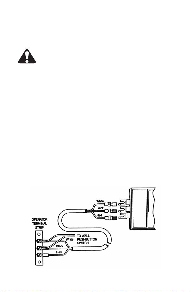
To Connect a Three-Tab Receiver:
1. Connect the cable wires to the receiver power terminals kee ping the wire col ors in order
as shown in the figure. The push-on receptacle on each wire is connected to the straight
tab of the receiver terminals.
2. Connect the wires from the other end of the cable to the operator terminals as follows:
(a) White wire to the terminal marked “1” or “24v”.
(b) Black wire to terminal marked “2” or “Relay”.
(c) Red wire to terminal “3” or “Common” - sometimes marked “Radio Power”.
(d) Connect the wall pushbutton switch across terminals 1 and 2, in parallel with the
white and black wires.
The numbers marked on terminals on some operators may be different from those
Note:
shown in the diagram. In all cases where the operato r terminals are lab eled “24v”, “Relay”,
and “Radio Power”, the wire color and word designation should be matched as shown in
the diagram.
Copyright © 1999 Linear Corporation 216665 A
Page 2
INSTRUCTIONS D’INSTALLATION
CÂBLE D’ADAPTATEUR D’ALIMENTATION
Modèle 1092-06
ATTENTION:
• Débranchez l’électricité avant toute installation ou réparation.
• Portez des lunettes de sécu rit é.
Le câble d’adaptateur d’alimentation, modèle 1092-06, permet de relier un récepteur de
télécommande à trois pattes à un ouvre-porte de garage qui a trois bornes peu accessibles
pour le montage direct du récepteur ou quand la séquence de numérotation n’est pas
conforme à la norme adoptée par le DORCMA.
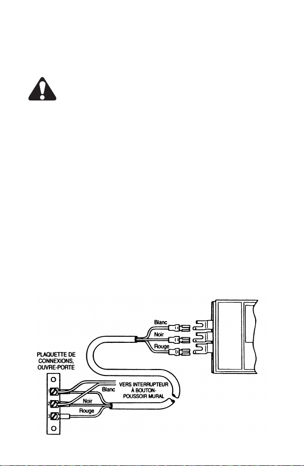
Pour Brancher Le Récepteur à Trois Pattes:
1. Branchez les fils du câble aux bornes d’alimentation du récepteur, avec les couleurs dans
l’ordre montré par la figure ci-dessous. La fiche à emboîter de chaque fil se relie à la
patte droite des bornes du récepteur.
2. Branchez les fils de l’autre extrémité du câble de borne de l’ouvre-porte, comme suit :
a) Fil blanc à la borne marquée “1” ou “24v”.
b) Fil noir à la borne marquée “2” ou “Relay”.
c) FiI rouge à la borne “3” ou “Common” - parfois marquée “Radio Powe r”.
d) Branchez l’interrupteur à bouton-poussoir mural aux bornes 1 et 2, en parallèle avec
les fils blanc et noir.
Remarque:
de ceux indiqués ci-dessous. Dans tous les cas où les bo rnes de l’ouvre-porte sont marquées “24v”, “Relay” et “Radio Power”, on doit respecter la couleur et la désignation des fils,
comme indiqué par la figure ci-dessous.
Les numéros indiqués sur les bornes de certains ouvre-portes peuvent différer
 Loading...