

Page 1

ATX Power Supply Tester
User Manual English
Benutzerhandbuch Deutsch
Manuel Utilisateur Fançais
Manuale d’uso Italiano
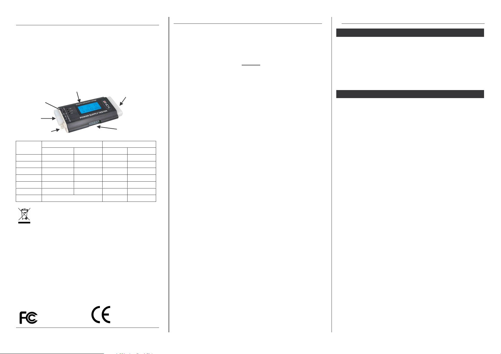
+12V/+3.3V/+5V
Indicator
4P/ 6P/ 8P
Connector
3.5” Connector
+5V
-12V
+12V1
+12V2
3.3V
5VSB
P.G.
For Home and Office Use
Tested to Comply with FCC Standards
© LINDY ELECTRONICS LIMITED & LINDY-ELEKTRONIK GMBH - 2nd Edition - JAN 2008
SATA Connector
20/ 24 Pin PSU Connector
5.25” Connector
Permissible Range Indicated Range
(Min) (Max) (Min) (Max)
+4.75V +5.25V 4.0V 6.0V
-11V -13V -10V -14V
+11V +13V +10V +14V
+11V +13V +10V +14V
+3.14V +3.47V +2.0 +4.5V
+4.75V +5.25V +4.0V +6.0V
100ms 900ms 0ms 990ms
LINDY No. 43058
www.LINDY.com
English Manual
Specifications
• Accurate voltage indicator (+/- 0.1V) tests:
o +12V1 / +5V / +3.3V / +5V / 5V Standby / +12V2 / -12V
• Connections:
o 20 Pin ATX PSU or 24 Pin ATX PSU
o 4P / 6P / 8P connector
o 5.25" type power / 3.5" type power / SATA power
• Low voltage, over voltage and no voltage, with audio alarms
• ATX PG (Power Good) value display
Operation
Important:
1. You must only connect one of the three 5.25”, 3.5” or a SATA
power connector to the unit at any one time,
2. Your ATX power supply must not be powered when
connecting and disconnecting any of the connectors.
1. Once all power connections have been made, switch on the
power. After switching on, you will hear two short beeps and the LCD
display will show the PG (Power Good) values. The value for PG
must be within a 100 to 900ms tolerance level.
2. If the PG values are out of tolerance or if there is no voltage
detected on one of the connectors, the unit will beep constantly. The
LCD screen will display LL on the affected connector.
3. The voltage level “+12V2” refers to the P4/P6/P8 connector only.
If there is no P4/P6/P8 plug attached, then "LL" will flash on the LCD
and the unit will constantly beep – anyhow, this is NOT an
indication for a faulty power supply!
If any voltage is lower or higher than the stated
(see table), or not available, the LCD will only show "LL" or "HH"
respectively, indicating that the power supply is NOT OK.
A voltage within the Indicated Range will be displayed on the LCD.
20/24 Pin:
When either a 20 pin or 24 pin connector is attached, the values of
the voltage input will be shown on the LCD
P4/P6/P8:
When either a P4, P6 or P8 connector is attached, the values of the
voltage input will be shown on the LCD under +12V2
5.25”/3.5”/ SATA :
When a 5.25” or 3.5” or SATA connection is made, only the
+12V/+5V/+3.3V indicator lights (+3.3V only for SATA) will light to
show a correct voltage input.
Indicated Range
Deutsches Benutzerhandbuch
Der Tester testet die Anschlüsse / Spannungen eines ATX Netzteils und zeigt an, ob Sie im Rahmen der Toleranzwerte liegen.
Ferner misst er, ob beim Einschalten des Netzteils alle Spannungen in der vorgegebenen Zeitspanne aufgebaut werden (PGWert). Daher müssen die ATX 20/24 Pol und einer der 4P/6P/8P
Stecker
werden.
Die SATA, 5,25“ und 3,5“ Anschlüsse können danach im laufenden
Betrieb angesteckt und geprüft werden.
HINWEIS: Schließen Sie von den drei SATA-, 5,25“- und 3,5“-Anschlüssen keine der Stecker gleichzeitig an den Tester an. Testen Sie
diese immer einzeln.
HINWEIS: Ältere Netzteile hatten einen 20 Pol ATX Stecker, später
abgelöst durch einen 24Pol ATX Stecker. Oft finden sich heute 24 Pol
Stecker an denen seitlich ein 4 Pol Stecker abgeklippst werden kann,
so dass der ATX 20 Pol Stecker (für ältere Mainboards) übrig bleibt.
Beide Arten können angeschlossen werden.
Nach dem Einschalten ertönen zwei kurze Pieptöne und das LCD
Display zeigt die Spannungen an. Der Wert für PG muss im Bereich
100 bis 900ms liegen. Liegt er außerhalb, so baut das Netzteil die
Spannungen NICHT im vorgegebenen Zeitraum auf.
Werden ungewöhnliche Spannungen außerhalb der zulässigen
Toleranzwerte (siehe Tabelle: Permissible Range) erkannt, so wird
ein Alarm (Piepton) ausgelöst. Die Alarm auslösenden Werte werden
durch Blinken am Display signalisiert.
Der Spannungswert +12V2 bezieht sich AUSSCHLIEßLICH auf die an
den P4/P6/P8-Steckern anliegende Spannung. Ist dort kein Stecker
angeschlossen, so blinkt in dieser Anzeige „LL“ und der Alarmton wird
ausgelöst. Falls alle anderen Anzeigen im LCD Display korrekt
innerhalb der Toleranzwerte liegen, ist das ATX Netzteil in Ordnung.
Die Spannungswerte werden, sofern sie im Angezeigten Bereich (s.
Tabelle Indicated Range) liegen, im LCD Display angezeigt, andernfalls wird „HH“ bei zu hoher oder „LL“ bei zu niedriger oder ganz
fehlender Spannung angezeigt. Die Spannungswerte sind OK wenn
sie im Toleranzbereich (s. Tabelle Permissible Range) liegen.
Wenn Ihr Netzteil mehrere 4P/6P/8P Anschlüsse aufweist, prüfen
Sie diese bitte nacheinander einzeln bei angeschlossenem ATX 20/24
Pol Stecker. Schalten Sie dazu jeweils das Netzteil aus und ein.
Prüfen Sie nach Abschluss dieser Tests die SATA, 5,25“ und 3,5“
Anschlüsse. Lassen Sie dazu die ATX 20/24 Pol und einen der
P4/P6/P8 Stecker angeschlossen.
Schließen Sie nacheinander die SATA-, 5,25“- und 3,5“-Stecker
einzeln an und überprüfen Sie die LED Kontrollleuchten (+12V /
+3,3V / +5V) links neben dem LCD Display.
Für den SATA-Anschluss müssen alle 3 LEDs leuchten. (Falls Sie
diesen Stecker verkehrt herum anschließen hat er keinen Kontakt und
es werden keine Spannungen angezeigt.)
Für den 5,25“- und 3,5“-Anschluss müssen nur die +12V und +5V
LEDs leuchten.
VOR EINSCHALTEN
des Netzteils angeschlossen
Page 2
Specifications
Le testeur teste les prises/tensions d’une alimentation ATX
doivent être
For
Home and Office
use
• Accurate voltage indicator (+/- 0.1V) tests:
o +12V1 / +5V / +3.3V / +5V / 5V Standby / +12V2 / -12V
• Connections:
o 20 Pin ATX PSU or 24 Pin ATX PSU
o 4P / 6P / 8P connector
o 5.25" type power / 3.5" type power / SATA power
• Low voltage, over voltage and no voltage, with audio alarms
• ATX PG (Power Good) value display
+12V/+3.3V/+5V
Indicator
SATA Connector
20/ 24 Pin PSU Connector
P4/P6/P8
Connector
3.5” Connector
Permissible Range Indicated Range
5.25” Connector
(Min) (Max) (Min) (Max)
+5V
-12V
+12V1
+12V2
3.3V
5VSB
P.G.
Europe
In 2006 the European Union introduced regulations (WEEE) for the collection and
recycling of all waste electrical and electronic equipment. It is no longer allowable to
simply throw away electrical and electronic equipment. Instead, these products must
enter the recycling process.
Each individual EU member state has implemented the WEEE regulations into national
law in slightly different ways. Please follow your national law when you want to dispose of
any electrical or electronic products. More details can be obtained from your national
WEEE recycling agency.
Deutschland
Die Europäische Union hat mit der WEEE Direktive umfassende Regelungen für die
Verschrottung und das Recycling von Elektro- und Elektronikprodukten geschaffen.
Diese wurden im ElektroG in deutsches Recht umgesetzt. Dieses Gesetz verbietet vom
24.März 2006 an das Entsorgen Elektro- und Elektronikgeräten über die Hausmülltonne!
Diese Geräte müssen den lokalen Sammelsystemen bzw. örtlichen Sammelstellen
zugeführt werden! Dort werden sie kostenlos entgegen genommen. Die Kosten für den
weiteren Recyclingprozess übernimmt die Gesamtheit der Gerätehersteller.
+4.75V +5.25V 4.0V 6.0V
-11V -13V -10V -14V
+11V +13V +10V +14V
+11V +13V +10V +14V
+3.14V +3.47V +2.0 +4.5V
+4.75V +5.25V +4.0V +6.0V
0ms 990ms
WEEE
Waste of Electrical and Electronic Equipment,
Recycling of Electronic Products
© LINDY ELECTRONICS LIMITED & LINDY-ELEKTRONIK GMBH - 2nd Edition - JAN 2008
Tested to comply with
FCC Standards.
LINDY No. 43058
Manuel Utilisateur
et montre si les résultats sont dans la plage de tolérance.
De plus, il mesure toutes les tensions de l’alimentation dans
un temps donné (Valeur PG).
Pour cela, les prises ATX 20/24 pins et 4P/6P/8P
connectées/déconnectées AVANT le branchement de
l’alimentation ATX.
Les connecteurs SATA, 5,25“ et 3,5“ peuvent ensuite être testés et
connectés.
NOTE: ne connectez pas ensemble les 3 prises SATA, 5,25“ et 3,5“, sur
le testeur. Testez les toujours une par une.
NOTE: les anciennes alimentations avaient un connecteur ATX 20 pins,
qui a ensuite été changé en connecteur ATX 24 pins. On trouve souvent
des connecteurs ATX 24 pins sur lesquels une prise 4pins
supplémentaire est clipsée, pour que la compatibilité avec les prises
ATX 20 pins reste (anciennes cartes mère). Dans les deux cas de figure,
vous pouvez utiliser le testeur.
Après la connexion du testeur, 2 courts bips sonores sont émis et l’écran
LCD affiche les tensions. La valeur PG doit être entre 100 et 900ms.
Sinon les tensions de l’alimentation ne sont pas dans la plage de
tolérance (tension dans un temps donné).
Si les tensions sont en dehors de la tolérance (voir tableau: Permissible
Range), une alarme (bip sonore) sera émise. Les valeurs seront
affichées sur l’écran LCD.
La valeur de tension +12V2 se réfère GENERALEMENT aux tensions
des connecteurs P4/P6/P8. Si aucune prise n’est connectée au testeur,
l’indicateur “LL“ clignote et une alarme sonore est émise. Si tous les
indicateurs de l’écran LCD sont compris dans la plage de tolérance,
l’alimentation ATX fonctionne correctement.
Les valeurs de tension s’afficheront sur l’écran LCD, si elles
correspondent à la plage de tolérance (voir tableau Indicated Range).
Sinon l’indicateur “HH“ s’affichera pour des surtensions, ou “ LL“ pour
des sous-tensions. Les valeurs de tension sont donc correctes tant
qu’elles sont comprises dans la plage de tolérance (voir tableau
Permissible Range).
Quand votre alimentation possède plusieurs connecteurs P4/P6/P8,
testez les un par un depuis le connecteur ATX 20/24 pins. Eteignez et
allumez à chaque fois l’alimentation.
Testez ensuite les connecteurs SATA, 5,25“ et 3,5“. Laissez les prises
ATX 20/24 pins et P4/P6/P8 connectés.
Connectez les prises SATA 5,25“ et 3,5“, une par une et contrôlez les
LEDs à gauche de l’écran LCD (+12V / +3,3V / +5V).
Pour les connecteurs SATA, les 3 LEDs doivent s’allumer. (Dans le cas
où ces connecteurs SATA sont montés à l’envers, aucune tension ne
sera affichée)
Pour les prises 5,25“ et 3,5“, les LEDs +12V et +5V LEDs doivent
s’allumer.
Manuale d’uso
Specifiche
• Indicatore di voltaggio (+/- 0.1V):
o +12V1 / +5V / +3.3V / +5V / 5V Standby / +12V2 / -12V
• Connettori:
o 20 Pin ATX PSU o 24 Pin ATX PSU
o 4P / 6P / 8P
o 5.25" power / 3.5" power / SATA power
• Allarme acustico per voltaggio basso, alto o assente
• Display ATX PG (Power Good)
Istruzioni per l’uso
Importante:
1. Occorre collegare uno dei tre connettori di alimentazione da
5.25”, 3.5” o SATA
2. L’alimentatore ATX non deve essere acceso durante la
connessione e la disconnessione dei connettori.
1. Una volta collegata l’alimentazione, accendere l’alimentatore. Dopo
l’accensione, sentirete due brevi segnali acustici e il display mostrerà
il valore PG (Power Good). Questo valore deve essere entro il livello
di tolleranza da 100 a 900ms.
2. Se il valore PG non rientra nel livello di tolleranza oppure se non
viene rilevato alcun voltaggio, il tester emetterà continuamente un
segnale acustico. Sul display LCD apparirà LL in corrispondenza del
connettore sul quale viene rilevato l’errore.
3. Il livello di voltaggio “+12V2” è riferito solo al connettore P4/P6/P8.
Se non viene collegato alcun connettore P4/P6/P8, apparirà sul
display "LL" e l’unità emetterà continuamente un segnale acustico –
In questo caso NON significa che l’alimentatore è difettoso!
Se il voltaggio è inferiore o superiore a quello indicato nelle colonne
Indicated Range
apparirà rispettivamente solo "LL" o "HH", e ciò significa che
l’alimentatore è difettoso.
Il voltaggio apparirà sul display qualora rientrasse tra quelli indicati
nella tabella.
20/24 Pin:
Se si collega un connettore da 20 o 24 pin, il voltaggio in ingresso
verrà visualizzato sul display LCD.
P4/P6/P8:
Se si collega un connettore P4, P6 o P8, il voltaggio in ingresso verrà
visualizzato sul display LCD sotto +12V2.
5.25”/3.5”/ SATA :
Con connessioni da 5.25”, 3.5” o SATA, appariranno gli indicatori
+12V/+5V/+3.3V (+3.3V solo per SATA) per segnalare il corretto
voltaggio in ingresso.
(vedi tabella), o non rilevabile, sul display
 Loading...