

Page 1

With Deutz Engine
351 807 1301 GB
Linde Fork Lift Truck
H 25 - 04 / H 30 - 04
Operating Instructions
0407
Page 2
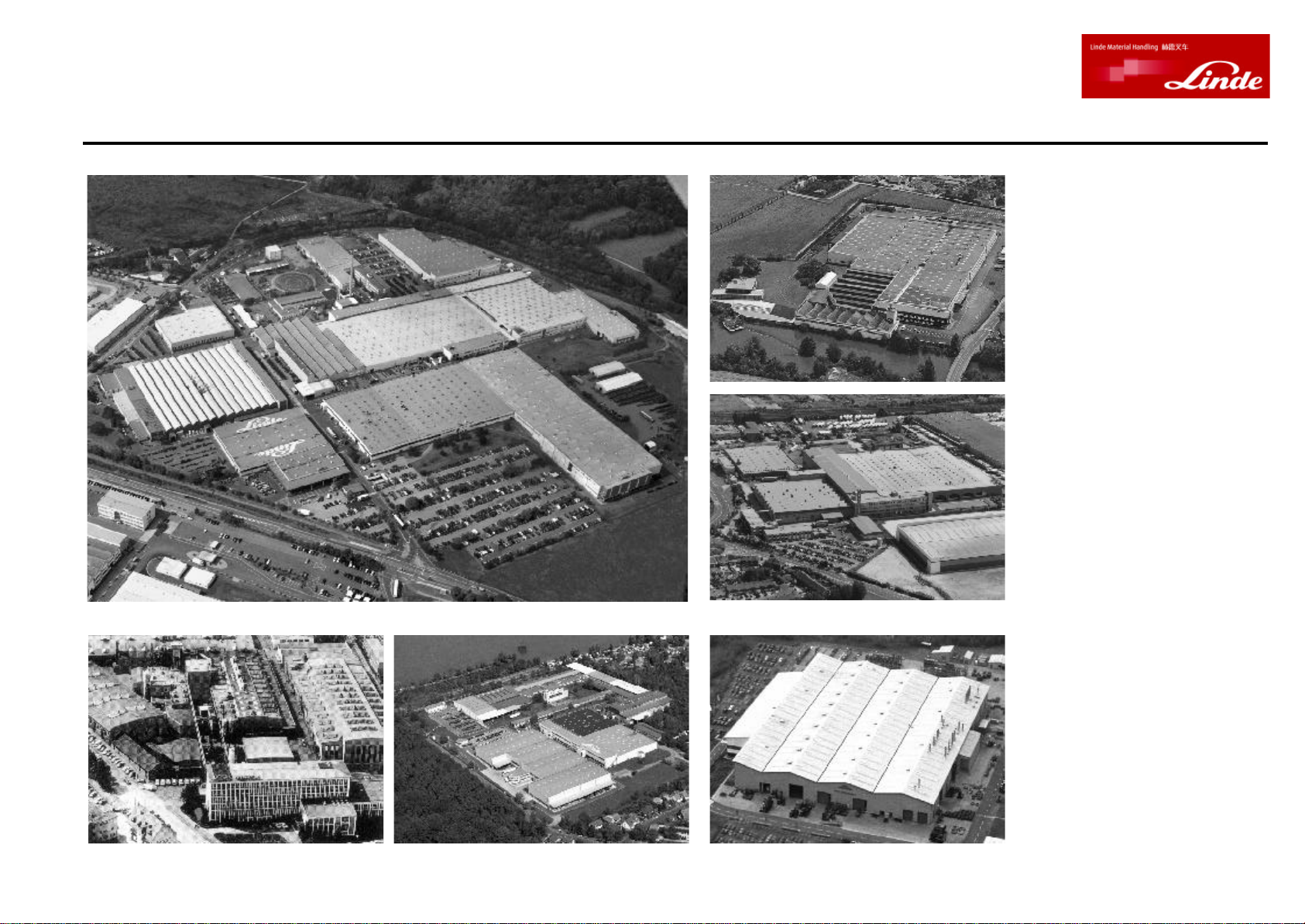
Linde - Your Partner
Linde AG
Linde Material Handling Division
Linde, an enterprise operating
worldwide in the investment
and service sector, is one of
the large industrial enterpris-
es in the EC with its three
business segments and six
divisions.
The Linde Material Handling
division is a leading manufac-
turer of industrial trucks and
hydraulics. It includes eight
manufacturing plants in the
Federal Republic of Germany,
France and Great Britain, as
well as subsidiaries and bran-
ches in all economically im-
portant countries.
Linde industrial trucks enjoy a
worldwide reputation - thanks
to their high quality in engin-
eering, performance and serv-
ice.
Werk II, Aschaffenburg-Nilkheim
Werk I, Aschaffenburg
Lansing Linde Ltd., Basingstoke
Fenwick-Linde, Ch鈚ellerault
Werk III, Kahl am Main
Linde Heavy Truck Division Ltd., Merthyr Tydfil
Page 3

Foreword
Your Linde lift trucks
offer the best in economy, safety and driving convenience.
Therefore it is mainly in the hands of the operator to preserve
the qualities of the trucks for a long and profitable service life
and to make full use of their benefits on the job.
These operating instructions tell you all you need to know
about starting, operation, running, and servicing the truck.
For maintenance and repair work not described in these
operating instructions special technical skill and knowledge, measuring equipment and special worshop tools are
often required. Please contact your authorised Linde dealer
for this service.
Only qualified persons authorised by Linde are allowed to
service the trucks.
For some attachments, the own operating instructions supplied with them are applicable.
Follow all hints for operating the lift truck and carry out the
maintenance and care prescribed in the inspection and
maintenance schedule regularly, on time and with the specified lubricants.
Keep a record of all maintenance services, otherwise your
warranty may become void.
The terms "front" "rear" "left" and "right" "refer to the position
in which the item concerned is installed in the truck, looking
forward in the travel direction.
Approved applications
Linde lift trucks are designed for transporting and lifting the
loads stated in the load capacity diagram.
In particular, we refer to the attached rules for the normal and
proper use of industrial trucks (VDMA) , the regulations of your
employer's liability insurance the traffic regulations.
The safety rules for the use of industrial trucks must be
followed under all circumstances by the responsible persons, especially by the operator and service personnel.
The user, and not Linde, is responsible for any danger
arising from applications not authorised by the manufacturer.
If you desire to use the truck for applications not mentioned
in the manual and convert or supplement it for this purpose,
please first contact your authorised Linde dealer.
No changes, especially conversions or modifications, may
be made on your fork truck without the prior permission of the
manufacturer.
351 807 1301 0407
Page 4

Foreword
Technical note
These operating instructions or excerpts thereof may only be
copied, translated or transmitted to third parties after prior
written approval by the manufacturer.
Linde pursues a policy of continuous progress in the design
and construction of its products. As a result, the illustrations
and technical details referring to design, fittings and engineering of lift trucks are subject to change if progress warrants it.
Therefore, the manufacturer will not accept any claims based
on the specifications, illustrations and descriptions contained in this operating manual.
Please submit all enquiries concerning your fork truck and all
orders for spare parts to your authorised distributor, making
sure to state your correct shipping address.
For repairs, use only genuine Linde spare parts to ensure
that your Linde fork truck will maintain its original technical
standard.
When ordering spare parts, it is important to specify the part
numbers and to include the following truck data:
Lift truck model:________________________________
Serial number/Year built: _________________________
351 807 1301 0407
Handing-over date: _____________________________
Truck takeover
Every fork truck undergoes careful inspection before leaving
the factory in order to make sure that it will be in satisfactory
condition and fully equipped as ordered when delivered to
the customer. Authorised distributors are under obligation to
re-inspect the truck before delivery and to hand it over in good
order.
In order to avoid later complaints and inconvenience to
customers, you are requested to ascertain that the truck is in
satisfactory condition and fully equipped at the time of delivery and to acknowledge orderly handing/taking over of the
truck in the manufacturer's certificate of conformity.
The following technical manuals are supplied with each fork
truck:
1 Operating manual
1 EC certificate of conformity
(The manufacturer certifies that the industrial truck conforms to EC directives for machines)
1 Rules for the normal and proper use of industrial trucks
(VDMA)
Additionally specify the production no. of engine, mast, hydraulic pump and compact axle when ordering parts for
these assemblies.
Engine number:________________________________
Mast number: _________________________________
Mast lift height: _____________________________ mm
Hydraulic pump number: _________________________
Compact axle number: __________________________
When taking over the fork lift truck, transfer the data from the
assembly type plates into this manual.
Wishing you satisfactory operation,
Linde AG
Linde Material Handling Division
Aschaffenburg
Page 5

351 807 1301 0407
Page 6
1254378
6
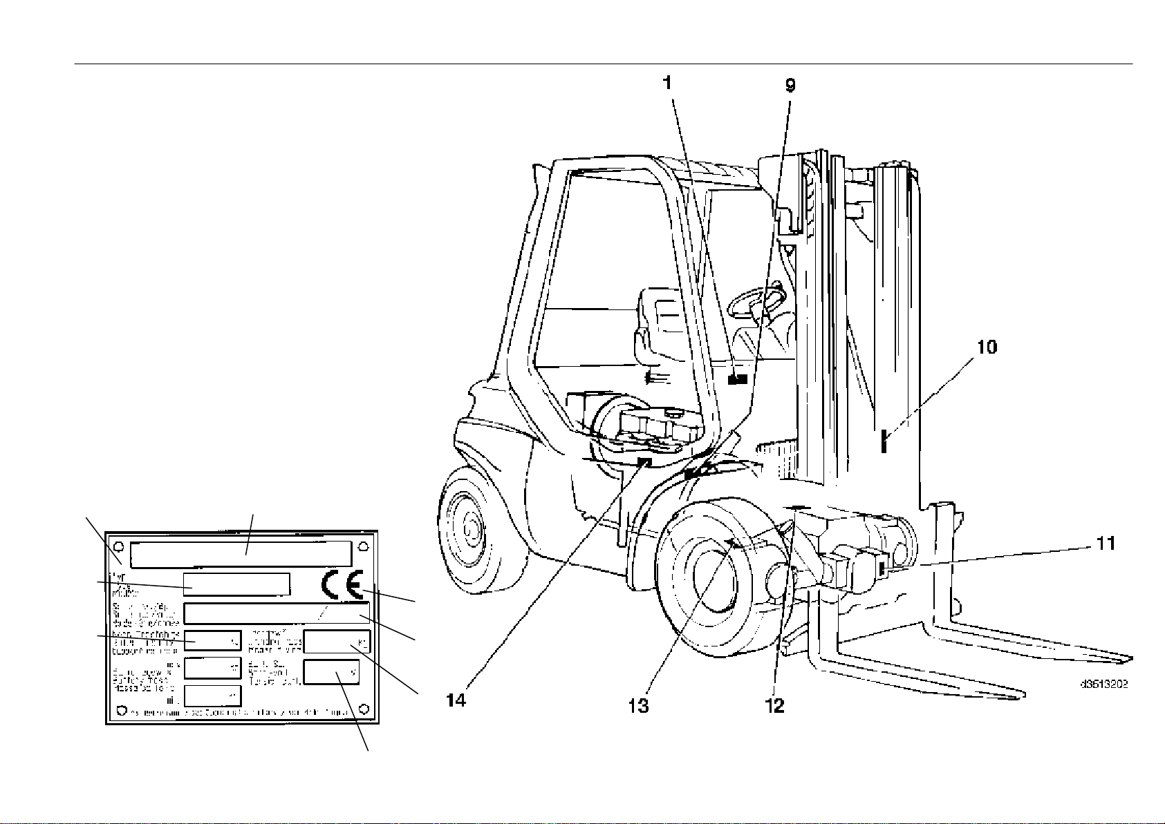
Type plates Description
1 Lift truck type plate
2 Manufacturer
3 CE symbol
(The symbol certifies that EC directives for machines
and all applicable guidelines are fulfilled.)
4 Serial no./year
5 Unladen mass
6 Battery voltage
7 Rated load capacity
8 Type
9 Chassis no. (stamped on side)
10 Mast no. (glued)
11 Hydraulic pump type plate
12 Compact axle type plate
13 Right hub differential type plate
14 Engine type plate
351 807 1301 0407
Page 7
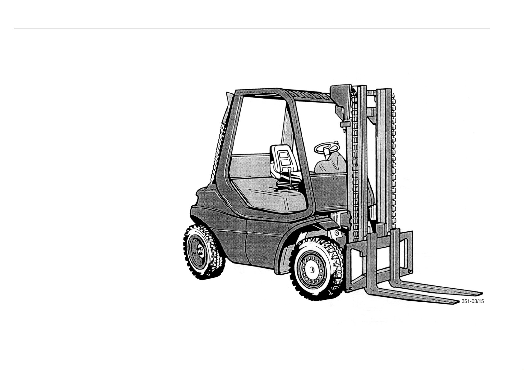
Fork lift truck H 25 / H 30 with Deutz engine Description
The latest technology,
simple and ergonomic operation,
energy saving, environment-conscious and minimal
maintenance,
simple and ergonomic operation,
solid manufacture
and for availability of your lift truck
nearly all parts of our own manufacture!
The success of a company
with about 9600 employees in eight manufacturing sites.
351 807 1301 0407
Driver's position and operating features are according to the
latest findings of ergonomics. Each control is designed in
regard to positioning and operation for the driver's convenience to guarantee effortless and therefore safe operation.
Of course, this also includes the easy hydrostatic power
steering with a kick-back safety, the service-proved doublepedal travel control system: forward travel with the right foot,
reversing with the left, and only one main control lever for all
mast functions.
Page 8

351 807 1301 0407
Page 9

Page
Page
Page
Table of contents Description
Foreword ............................................................2
Approved applications .............................................................. 2
Technical note ............................................................................ 3
Truck takeover ............................................................................ 3
Description............................................................................ 5
Type plates .................................................................................. 5
Technical data ..........................................................................10
Noise emission value ............................................................12
Technical description .............................................................13
Engine ....................................................................................13
Hydraulic system ..................................................................13
Operation ...............................................................................13
Brakes ....................................................................................13
Steering..................................................................................13
Electrical system ..................................................................13
General view .............................................................................14
Controls and indicators ..........................................................15
Composite instrument ...........................................................17
Beginning operation......................................................18
Safety rules ...............................................................................18
Important safety information .................................................18
Handling fuels and lubricants ..............................................18
Accident prevention check .....................................................19
Operation of industrial trucks in the plant area.................19
Diesel engine emissions ......................................................19
Soot particulate filter inspection ...........................................19
Running-in instructions ..........................................................19
Experts .......................................................................................19
Checks and services before initial operation....................19
Daily checks ..............................................................................19
Daily checks and servicing before operation ....................20
Opening the engine cover......................................................20
Closing the engine cover .......................................................20
Checking the fuel level ...........................................................20
Filling fuel ..................................................................................21
Checking the engine oil level................................................21
Checking the tyre pressure ...................................................22
Applying, opening the seat belt ............................................23
Adjusting the operator seat ...................................................23
Starting the engine ..................................................................24
Cold start ...................................................................................25
Stopping the engine................................................................25
Malfunctions during operation ..............................................25
Operation..............................................................................26
Driving ........................................................................................26
Forward travel .......................................................................26
Reverse travel .......................................................................26
Changing the travel direction ............................................26
Stopping.................................................................................26
Single-pedal model ................................................................27
Steering system .......................................................................30
Steering..................................................................................30
Braking system ........................................................................30
Service brake ........................................................................30
Parking brake........................................................................30
Applying the parking brake.................................................30
Releasing the parking brake .............................................30
Central-lever control of lifting device and attachments ...31
Tilting the mast forward ......................................................31
Tilting the mast back ...........................................................31
Lifting the fork carriage .......................................................31
Lowering the fork carriage .................................................31
Operating the attachments ................................................31
Operating the sideshift .......................................................31
Operating the clamp ............................................................ 31
Single-lever control of lifting device and attachments .....32
Installation of additional equipment....................................33
Switching on the front working lights ...................................33
Switching on the rear working lights ...................................33
Switching on the lighting ........................................................33
Switching on the hazard warning light ................................33
Turning on the front windscreen wiper ...............................33
Turning on the rear windscreen wiper ................................33
Switching on the directional indicators ...............................33
Water heater .............................................................................34
Controls .................................................................................34
Fan motor fuse .....................................................................34
Operating the horn ..................................................................34
Data Logger ..............................................................................34
Fuses .........................................................................................35
Check the fuses, replace if necessary............................35
Fuses, soot particulate filter system ................................36
Before lifting a load .................................................................37
Adjusting the fork spread .......................................................38
Loading......................................................................................38
Travel with a load.....................................................................39
Unloading..................................................................................39
Parking the lift truck .................................................................39
Transport ...................................................................................40
Transport with lorry or low-bed semi-trailer.......................40
Hoisting the truck.....................................................................40
Hoisting the truck with a crane..........................................40
Hoisting the truck with the eyebolts .................................40
Changing wheels ....................................................................41
Trailer coupling ........................................................................41
Mast removal ............................................................................41
Towing instructions .................................................................42
Towing ....................................................................................42
Towing procedure ................................................................42
Releasing the multiple disc brake ...................................42
Opening the hydraulic by-pass valve ...............................42
After towing ............................................................................42
Re-establishing braking power ........................................42
Emergency exit for trucks with rear windscreen ...............43
Taking the truck out of operation ..........................................44
Measures before taking the truck out of operation .......44
Putting the truck back into operation................................44
Maintenance .......................................................................44
General information ................................................................44
Mast types .................................................................................45
Work on the mast and on the front part of the truck .........45
Securing the mast against tilting back ...............................45
Standard mast..........................................................................45
Securing the raised standard mast.....................................45
Duplex mast..............................................................................45
Securing the raised duplex mast.........................................46
Triplex mast ..............................................................................46
Securing the raised triplex mast ..........................................46
Checks and services after the first 50 service hours ......46
Inspection and maintenance schedule ..............................47
351 807 1301 0407
Page 10

Page
Page
Page
Table of contents Description
Inspection and maintenance as required.........49
Clean the lift truck ....................................................................49
Cleaning and spraying the mast chain...............................49
Cleaning the air filter...............................................................50
Cleaning with compressed air .........................................50
Renewing the safety element ...............................................51
Checking the dust discharge valve ......................................51
Cleaning the prefilter ..............................................................51
Regenerate the soot particulate filter (variant I)................52
Remove the soot particulate filter.....................................52
Clean the soot particulate filter .........................................52
Regenerate the soot particulate filter (variant II)...............53
Clean and check the radiator and hydraulic oil cooler
for leaks .................................................................................54
Drain the fuel system water preseparator .........................55
Tighten the wheel fasteners ..................................................56
Check the tyres for damage and foreign objects ..............56
Lubricate the steer axle, mast and tilt cylinder bearings 56
Check seat belt for condition and proper operation ........57
500-hour inspection and maintenance ..............58
Change the engine oil ............................................................58
Drain the engine oil.................................................................58
Top up engine oil.....................................................................58
351 807 1301 0407
Renew the engine oil filter cartridge....................................59
Clean the radiator and hydraulic oil cooler ........................59
Check and oil the pedals, travel control
and engine control linkages ..............................................59
Cleaning the air filter...............................................................60
Cleaning with compressed air .............................................60
Check the hydraulic system oil level ...................................61
Renew the fuel filter (every 12 months minimum) ...........61
Drain the fuel system water preseparator .........................62
Bleed the fuel system .............................................................62
Check and adjust valve clearance .......................................62
Battery: Check condition, electrolyte level and specific
gravity......................................................................................65
Check and oil other pivots and joints ..................................65
Clean and grease the steering axle ....................................66
Grease the mast and tilt cylinder bearings ........................66
Clean and lubricate the sideshift, check the fasteners ...67
Check the forks and fork quick-releases ...........................68
Check the pre-tension of double hoses
if attachments are fitted ......................................................68
Check the mast, lift chains and stops for condition,
mounting and operation .....................................................69
Adjust the lift chain length ......................................................69
Lubricate with chain spray.....................................................69
Renew the air filter element, check the vacuum switch ..69
Check the engine mounting for condition and tightness 69
1000-hour inspection and maintenance ...........70
Renew the air filter element,
check the vacuum switch ...................................................70
Check the engine mounting
for condition and tightness ................................................70
Check the air intake and exhaust pipes for leaks ............71
Check the hydraulic system, compact axle, pumps,
valves and lines for leaks ...................................................71
Hydraulic system: Renew the pressure, suction,
and breather filters ..............................................................72
Renew the pressure filter...................................................72
Renew the suction filter ......................................................72
Renew the breather filter ....................................................73
Check the soot particulate filter system (variant II) ..........73
Check the parking brake ........................................................73
Clean strainer of fuel pump...................................................74
Check the V-belt.......................................................................74
Tighten the V-belt.....................................................................75
Check and adjust the time belt and tension pulley..........75
Renew the hydraulic oil ..........................................................77
Filling/adding hydraulic oil.....................................................77
6000-hour inspection and maintenance ...........78
Renew the injection nozzles ..................................................78
Renew the mounting of the engine .....................................78
Inspection and maintenance data .......................................79
Fuel and oil recommendations ............................................80
Engine oils ............................................................................80
Oil grades ..............................................................................80
Oil viscosity............................................................................80
Diesel fuel .............................................................................81
Hydraulic oil...........................................................................81
Lubricating grease ..............................................................81
Battery grease.......................................................................81
Chain spray...........................................................................81
Troubleshooting guide (Diesel engine) .............................82
Troubleshooting guide (hydraulic system)........................84
Wiring diagram .........................................................................85
Wiring diagram (options).......................................................87
Hydraulic circuit diagram .......................................................90
Check the mounting of the compact axle at the engine ..63
Check the mounting of the engine, counterweight,
overhead guard, steering axle, tilt cylinder
and wheel drives for tightness..........................................63
Checking the soot particulate filter system (variant I)......64
Check electric cables, cable connectors
and connections for condition and tightness ................64
3000-hour inspection and maintenance ...........76
Check crankcase pressure vent valve ................................76
Check the injection nozzles ...................................................76
Renew the V-belt......................................................................76
Renew the time belt and tension pulley.............................77
Page 11
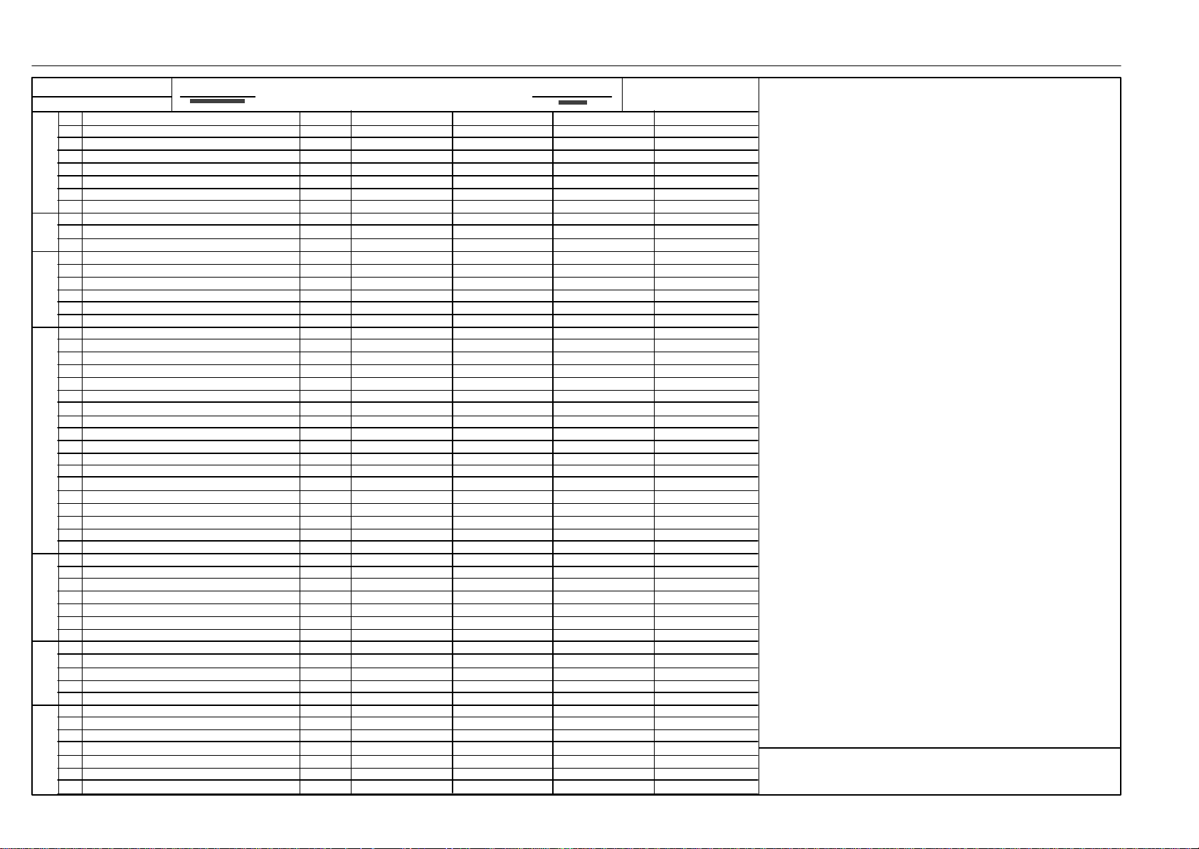
Technical data Description
VDI 2198
DFG
Forklift Trucks
Data Sheet for Material Handling Equipment
Apral 2007
1.1 Manufacturer (see page 1)
1.2 Model designation
1.3 Power unit: battery, diesel, petrol, LP gas, mains power
1.4 Operation: manual, pedestrian, stand-on, seated, order picker
1.5 Load capacity Q [t]
1.6 Load centre c [mm]
CharacteristicsWeightWheels and TyresDimensionsPerformance
1.8 Axle centre to fork face x [mm]
1.9 Wheelbase y [mm]
2.1 Service weight [kg]
2.2 Axle load with load, front/rear [kg]
2.3 Axle load without load, front/rear [kg]
3.1 Tyres, front/rear (SE = CS superelastic, P = pneumatic)
3.2 Tyre size, front
3.3 Tyre size, rear
3.5 Wheels, number front/rear (x = driven)
3.6 Track width, front b10 [mm]
3.7 Track width, rear b11 [mm]
4.1 Mast/fork carriage tilt, forward/backward degree
4.2 Height of mast, lowered h1 [mm
4.3 Free lift h2 [mm]
4.4 Lift h3 [mm]
4.5 Height of mast, extended h4 [mm]
4.7 Height of overhead guard (cabin) h6 [mm]
4.8 Height of seat/stand-on platform h7 [mm]
4.20 Length to fork face l2 [mm]
4.21 Overall width b1/b2 [mm]
4.22 Fork dimensions s/e/l [mm]
4.23 Fork carriage to DIN 15173, class/form A, B
4.24 Width of fork carriage b3 [mm]
4.31 Ground clearance, mast m1 [mm]
4.32 Ground clearance, centre of wheel base m2 [mm]
4.33 Aisle width with pallets 1000x1200 across forks Ast [mm]
4.34 Aisle width with pallets 800x1200 along forks Ast [mm]
4.35 Turning radius Wa [mm]
4.36 Minimum distance between the centres of rotation b13 [mm]
5.1 Travel speed, with/without load km/h
5.2 Lifting speed, with/without load m/s
5.3 Lowering speed, with/without load m/s
5.5 Tractive force, with/without load, 60 minute rating N
5.7 Climbing ability with/without load, 30 minute rating % 6)
5.9 Acceleration time with/without load (first 10 m) s
5.10 Service brake
7.1 Manufacturer of engine/type
7.2 Engine rated power to ISO 1585 kW
7.3 Rated rpm min
7.4 Number of cylinders / cc n/cm
IC engineOthers
7.5 Fuel consumption to VDI 2198 l/h kg/h
8.1 Type of drive control
8.2 Working pressure for attachments bar
8.4 Mean noise level at driver's ear to EN 12053 dB (A)
8.5 Towing coupling, design/type DIN, no.
-1
3
Linde
H 25
Diesel
seated
2,5
500
512.5
1715
4336
6160 / 676
2120 / 2216
P
7.00 - 12 / 16PR
6.50 - 10 / 10PR
2 (4) x / 2
3) 4)
990 (1220)
942
5 / 9, 5 / 9, 5 / 6
2405 (2110 / 2110)
150
3050 (2750 / 4025)
3885 (3535 / 4810)
2250 (2070 or 2550)
1135 (1064 or 1435)
2650
10)
1164
45 x 100 x 1000
2 A
10)
1150
130
160
4003
4203
2290
580
22 / 23
0.52 / 0.56
0.52 / 0.45
18800 / 14000
21 / 31
6.0 / 5.0
hydrostatic
Deutz D2011L04
36.9
2100
4 / 3108
12 )
2,5l / h
hydrostatic / stepless
170 (185)
80.2
11)
1)
2)
5)
6) 7)
8)
8)
9)
9)
Linde
H 30
Diesel
seated
3,0
500
517.5
1785
4835
7056 / 779
2301 / 2534
P
27 x 10 - 12 / 14PR
23 x 9 - 10 / 14PR
2 (4) x / 2
932
150
2731.5
1300
3 A
1300
140
160
4078
4278
2360
580
22 / 23
0.52 / 0.57
0.52 / 0.45
23 / 29
6.2 / 5.2
hydrostatic
36.9
2100
4 / 3108
2.62l / h
200 (215)
80.2
3) 4)
10)
10)
12 )
11)
1053 (1220)
5 / 9, 5 / 9, 5 / 6
2405 (2110 / 2110)
3050 (2750 / 4025)
3885 (3535 / 4810)
2250 (2070 or 2550)
1135 (1064 or 1435)
45 x 122 x 1000
18200 / 16900
Deutz D2011L04
hydrostatic / stepless
Notes:
1) Optional: SE Type 27x10-12/14PR.7.00-12/16PR
twin type
2) Optional: SE Type 6.5-10, 23x9-10
3) Figure in brackets refer to twin tyres
4) 27x10-12 type, 1053mm, 28x9-15 type 975mm
1)
2)
5)
6) 7)
8)
8)
9)
9)
5) Standard , Dupiex, Triplex mast
6) Standard mast with 150mm free lift
7) Figure in brackets refer to Duplex mast / Triplex mast
8) Figure in brackets refer to Duplex mast / Triplex mast
9) Figure in brackets refer to optional equipment
10) Different type vs different figures
11) Figure in brackets refer to Triplex mast
12) Test by 45 cycles of norm VDI 2198
351 807 1301 0407
Page 12
Technical data Description
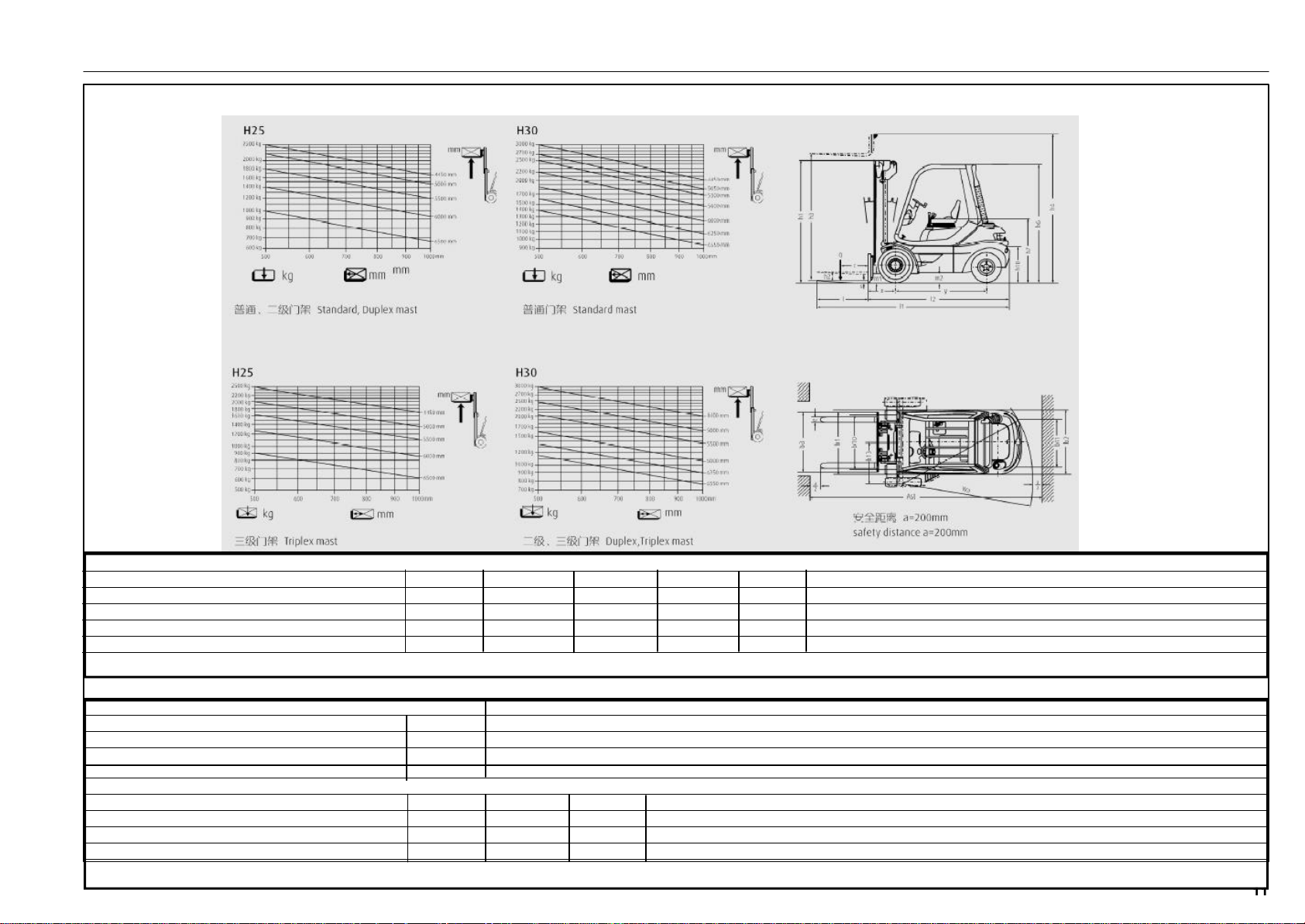
Load capacity diagrams for standard, duplex masts and triplex mast with standard fork carriage:
351 807 1301.0407
Standard lift mast (in mm) H25/30
Lift h3 3050 4050 4650 5150 5650
Mast lowered with specified free lift h1 2360 2860 3160 3410 3610
Mast lowered with 150mm free lift h1* 2405 2905 3205 3455 3655
Mast extended h4 3855 4855 5455 5955 6355
Free lift h2 150 150 150 150 150
H25 Choese SE type if list height > 4750mm H30 Choese SE type if list height > 5050mm
Duplex lift mast (in mm) H25/30
Lift h3 2750
Mast lowered with specified free lift h1 2110
Mast extended h4 3535
Free lift h2 1475
Triplex lift mast (in mm) H25/30
Lift h3 4025 5075 6275
Mast lowered with specified free lift h1 2110 2460 2860
Mast extended h4 4810 5860 7060
Free lift h2 1475 1825 2225
Choese SE type if list height > 4975mm Other lifting heights and values for triplex mast on request.
Page 13

Technical data Description
Noise emission levels
Determined in a test cycle in accordance with EN 12053 from
the weighted values in the operating modes DRIVING, LIFTING, IDLING.
Noise level at driver's station
H 25 - H 30 L
Uncertainty KPA= 4 dB (A)
Sound level at driver's place
Llifting with rated load LPa=81.8 dB (A)
Lower idling LPb=67.8dB (A)
80% rated speed LPc=78.4dB (A)
Uncertainty KPA= 4 dB (A
Guaranteed acoustic power level
Acc. to directive 2000/14/EC LWA=101 dB (A)
The directive legally requires this information. This value has
been calculated from the acoustic power levels for "Lifting"
and "Driving" and is only be used as a comparable value for
different trucks. For the determination of the real environmental noise stress this value is less appropriate, as it is not
representative of normal truck operation, which includes
"Idling".
=80.2dB (A)
PAZ
351 807 1301.0407
NOTE
Higher or lower noise emissions can exist during operation of the truck, for example due to type of operation,
environmental influences and additional noise emission
sources.
Page 14

Technical description Description
The series 351 fork trucks are designed for handling loads
weighing up to 2.5 tonnes with model H 25, 3 tonnes with
model H 30 .
The compact design and a small turning radius make the
trucks especially suitable for close passages and narrow
aisles.
Engine
The truck is equipped with a 4-cylinder four-stroke IC engine.
It drives the hydraulic pumps at load-dependent speed.
The engine is cooled by a closed-loop oil circuit with the oil
pump in the oil sump.
The lubrication system is a forced-feed type lubrication with
the oil pump in the oil sump.
A dry air filter with a paper cartridge cleans the combustion
air.
Hydraulic system
The traction drive consists of a variable-displacement pump
and two fixed-displacement motors installed as a unit in the
compact axle, and a tandem pump (fixed displacement) for
351 807 1301.0407
the working hydraulics and power steering system.
Travel direction and speed are controlled by accelerator
pedals via the variable-displacement pump.
The fixed-displacement motors in the drive axle are supplied
with oil by the variable-displacement pump, and they each
power a drive wheel via a two-stage reduction gearbox.
Operation
The variable-displacement hydraulic pump and travel speed
are simultaneously controlled by one pedal each for forward
and reverse travel. With the hydrostatic drive truck speed can
be regulated from a standstill up to maximum speed with
infinitely variable control in both directions. The double pedal
control permits easy as well as safe and quick handling of the
lift truck.
Both hands are always free for steering and control of the
work movements. The result is quick reversing and efficient
stacking.
There is only one control lever (main control lever) for controlling the work motions lifting, lowering and tilting. For the
operation of additional attachments, further control levers
are installed.
Brakes
The hydrostatic transmission is used as service brake. The
two disc brakes integrated in the compact axle are utilized as
parking brake.
When the engine is stopped, the disc brakes are applied =
automatic braking.
The brake pedal is also designed as parking brake so that
it must be locked mechanically when the truck is shut down.
Steering
The steering system consists of a hydrostatic steering system, which operates the rear wheels by the steering wheel
via the steering cylinder.
The steering system can also be operated when the engine
is stopped but a greater effort is required to turn the steering
wheel.
Electrical system
The electrical system is supplied by a three-phase current
generator with 12 VDC. A 12 V battery is installed for starting
the engine.
Page 15
General view Description
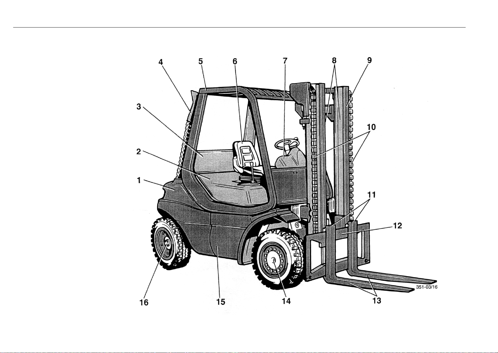
1 Counterweight
2 Engine cover
3 Battery compartment
4 Rear silencer
5 Overhead guard
6 Driver抯 seat
7 Instrument panel
8 Lift cylinder (not shown)
9 Mast
10 Lift chain
11 Fork quick-releases
12 Fork carriage
13 Forks
14 Wheel drive
15 Chassis
16 Steering axle
351 807 1301.0407
Page 16
Controls and indicators Description
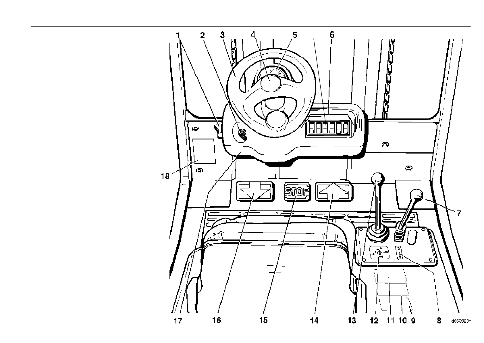
1 Parking brake lever
2 Ignition switch with switch key
3 Steering wheel/power steering
4 Horn button
5 Composite instrument
5a Rrain the fuel system water pre-separator
warning light
6 Toggle switch for auxiliary hydraulics*
7 Control lever for auxiliary hydraulics
(attachments)*
8 Symbol label for auxiliary hydraulics (attachments)*
9 Notice plate
10 Load capacity plate (attachment)*
11 Load capacity diagram
351 807 1301.0407
12 Symbol label for working hydraulics
5a
13 Control lever for working hydraulics
14 Forward accelerator pedal
15 Brake pedal
16 Reverse accelerator pedal
17 Fuses (in lower part of control console)
* Option
Page 17

351 807 1301.0407
Page 18
Composite instrument Description
* Option
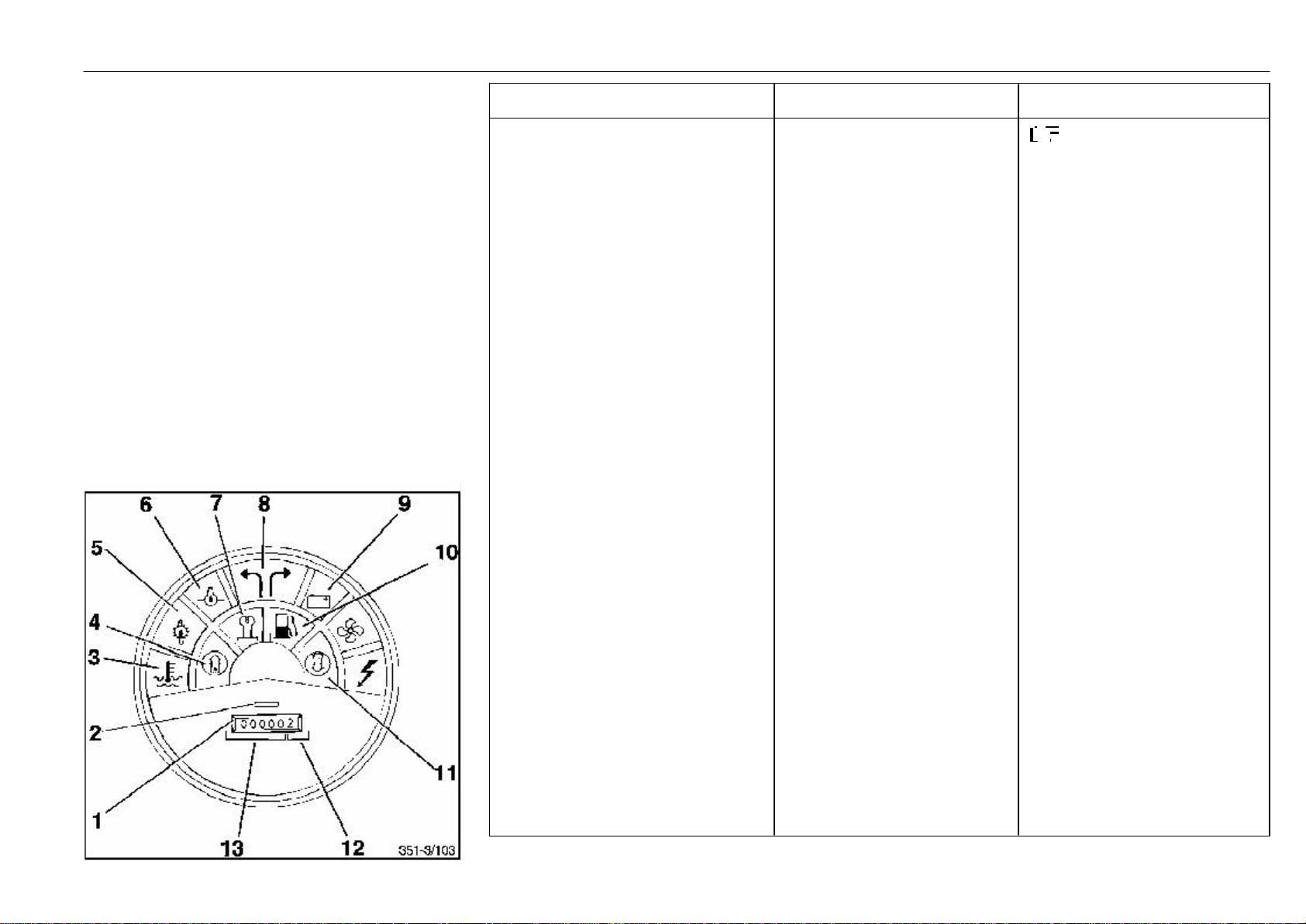
The composite instrument contains the following control and
indicator elements:
1 Hour meter
2 Hour meter on light
3 Cooling oil temperature warning light
4 Soot particulate filter warning light
5 Oil temperature warning light for hydraulic system
6 Engine oil pressure warning light
7 Preheat indicator light
8 Flasher warning light
9 Discharge indicator light
10 Fuel level warning light
11 Air filter warning light
351 807 1301.0407
Indicator element Function Possible fault(s)
Hour meter (1). The left digits (13) indicates lift truck service NOTE
indicate full service hours, the hours. The meter indicates the Record elapsed service hours
right digit (12) 1/10th of an hour. elapsed service hours of the when replacing a defective hour-
truck and the required meter. Record data on durable
inspection and maintenance tape and affix next to the hour
services. meter.
"ON" light for hour meter (2) indicates operation of meter
Cooling oil temperature warning light (3) indicates coolant temperature is - fan V-belt slack
too high - radiator dirty
- leak in cooling circuit
- low ing oil level
Soot particulate filter warning light* (4) indicates that the soot particle filter - regenerate the soot particulate
must be regenerated filter
Oil temperature warning light monitors the oil temperature of - oil level in hydraulic system is
(5) for hydraulic system the hydraulic system too low
- oil not as specified
- oil filter clogged
- dirt on oil cooler
Engine oil pressure warning indicates low oil pressure of - low oil level in crankcase
light (6) engine lubrication - engine is overheated
- oil not as specified
- internal leakage in lubricating
system
Preheat indicator light* (7) indicates cold start* function
Flasher warning light* (8) indicates function of flasher
unit when flasher is turned on
Discharge indicator light (9) indicates malfunctions in the - V-belt broken or slipping
electrical system - cables faulty
- alternator faulty
- regulator or charger switch faulty
Fuel level warning light (10) indicates a fuel reserve of
approx. 5.5 litres.
Air filter warning light (11) indicates restriced air filter element - air filter element restricted
Page 19
Safety rules Beginning operation
The responsible persons, particularly the truck operator and
servicing personnel, must be instructed in the safety guidelines for the normal and proper use of industrial trucks
included with these operating instructions.
The employer must ensure that the operator has understood
all safety informations.
Please observe the guidelines and safety rules therein for
example:
- information on the operation of industrial trucks
- rules for roadways and work areas
- rights, duties and safety rules for the operator
- operation in special areas
- information related to starting, driving and braking
- service and repair information
- recurrent inspections, accident prevention check
- disposal of greases, oil and batteries
- remaining risks.
The operator (employer) or the responsible person must
ensure that all the guidelines and safety rules applicable for
your truck are observed.
When instructing a trained operator, acquaint him with the
- special features of the lift truck (double-pedal control,
main control lever, brake pedal)
- optional attachments
- special operating and working area characteristics,
by training and practicing driving, shifting and steering operations until they are completely mastered.
Only then start to practice shelf-stacking.
The stability of the truck in the work area is ensured if
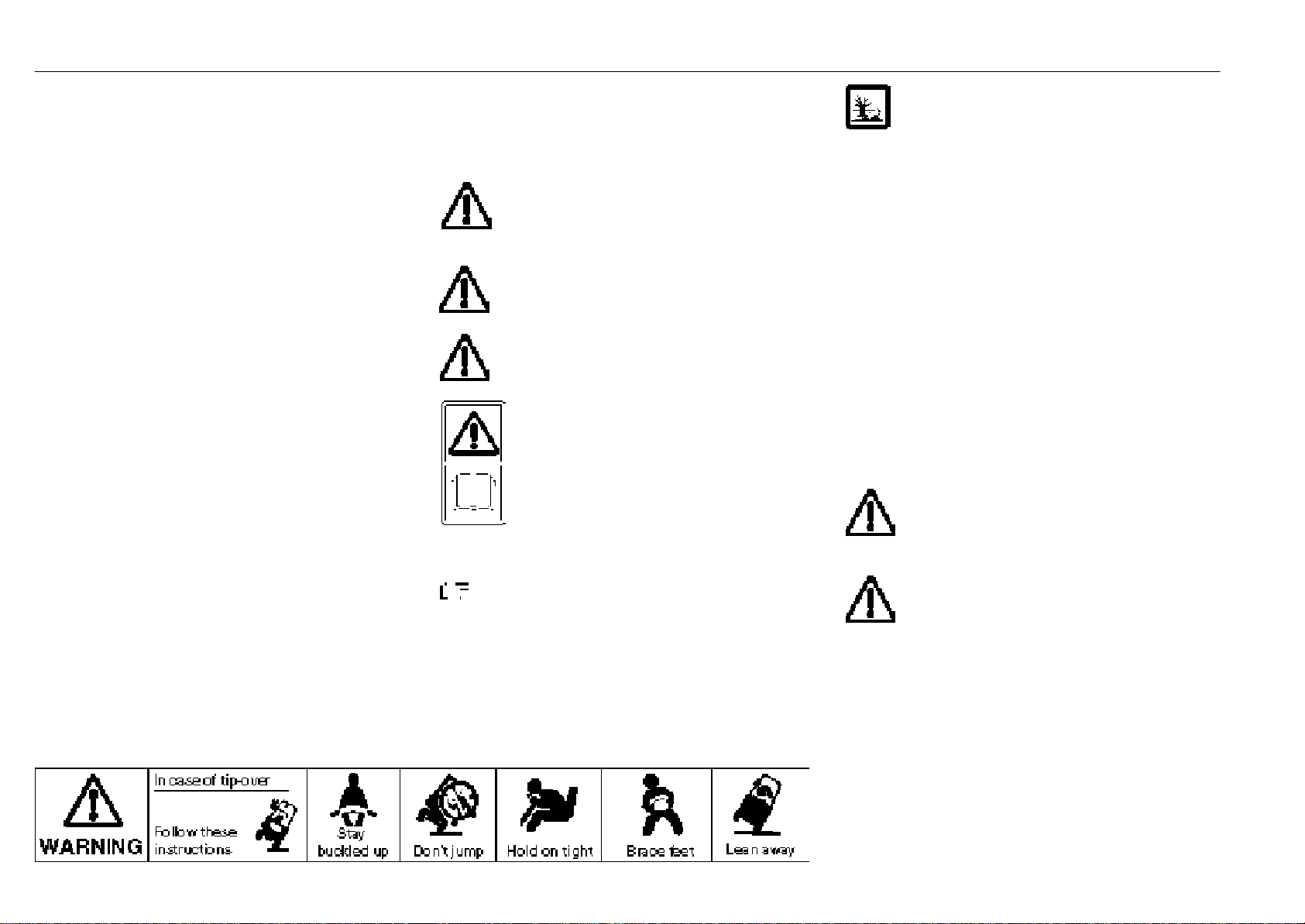
employed properly. Should the truck tip over during an unauthorised application or due to incorrect operation, always
follow the instructions depicted below.
Important safety information
The precautions WARNING, CAUTION, ATTENTION and
NOTE in this manual are provided to indicate special dangers or unusual information requiring special identification:
WARNING
indicates hazards that may result in personal
injury or death and/or substantial damage to the
product.
CAUTION
indicates hazards that may result in personal
injury and/or substantial damage to the product.
ATTENTION
indicates hazards that may result in damage to or
destruction of the product.
This note is found on various positions of the
truck where special attention is required. Read
the appropriate section of your operating instructions.
Further warning notices are also used for your safety. Please
observe the various symbols.
NOTE
identifies technical information requiring special attention
because the connection may not even be obvious to skilled
personnel.
Handling fuels and lubricants
Always handle fuels and lubricants as required and
as specified by the manufacturer.
Only store fuels and lubricants in approved containers at
specified storage places. As they could be inflammable, do
not contact them with hot objects or a naked flame.
Only use clean containers when replenishing fuels and
lubricants.
Follow the manufacturer's safety and disposal instructions
when using fuels and lubricants and cleaning compounds.
Avoid spilling fuels and lubricants. Remove any spillage
immediately with a suitable binding agent and dispose of as
specified.
Also dispose of used or contaminated fuels and lubricants
as specified.
Follow laws and regulations.
Clean the area surrounding the part in question before
lubrication, filter renewal or repairs in the hydraulic system.
Discard parts in a way friendly to the environment.
CAUTION
Do not allow hydraulic oil under pressure, for
example at a leak, to penetrate the skin. Medical
aid is required if such an injury occurs.
CAUTION
Improper handling of coolants and coolant additives puts your health and the environment at risk.
351 807 1301.0407
Page 20

Safety rules Beginning operation
Accident prevention check
The accident prevention rules in some countries prescribe
that the forklift truck must be checked at least once a year for
proper working condition by trained personnel. Please contact your authorised dealer in this regard.
Operation of industrial trucks in the plant
area
ATTENTION
Many plant areas are so-called limited public
traffic areas.
We advise you to check if your company liability insurance
covers any damages occurring with your fork truck against
third parties on so-called limited public traffic areas.
Diesel engine emissions
In Germany, fork trucks equipped with diesel engines must
conform to TRGS 554. According to this regulation, diesel
emissions are carcinogenic and they should, if at all possible, not permeate the air of workplaces.
If trucks equipped with diesel engines are used in totally or
partially enclosed spaces, the labour protection authority
must first be notified. Appropriate notices must be posted in
351 807 1301.0407
the work areas (refer to TRGS 554 for an example).
\
Soot particulate filter inspection
(option)
The responsible authorities specify that soot particulate
filters must be inspected and serviced every six months by an
expert. The results of the inspection must be recorded in a
Diesel Engine Emissions Inspection Certificateand attached to the log book (e.g. the truck Accident Prevention
Inspection booklet).
Running-in instructions
The lift truck can be operated at full speed directly. Avoid
sustained high loads on the working hydraulic system and
the travel drive in the first 50 hours of operation.
Tighten wheel nuts daily before each shift until they are
seated firmly, i.e. until no further tightening is possible.
Tighten opposite wheel fasteners to a torque of:
front: ..................................................................................195 Nm
rear:...................................................................................400 Nm
NOTE
Observe the tightening instructions on the tag attached to
the steering column.
Experts
Experts are specially skilled persons who have thorough
knowledge and experience in servicing and testing industrial
trucks and being furthermore sufficiently familiar with the
national industrial safety and accident prevention regulations and all further general technical rules and guidelines
(DIN and ISO standards, technical rules arising from EC
directives or EEA agreements), so that they can give a
qualified judgement upon the safe operating conditions of
the truck.
Checks and services before initial
operation
- Engine oil level
- Coolant level in the reservoir
- Fill fuel
- Battery: check condition, electolyte level and specific
gravity
- Tyre pressure
- Tighten wheel fasteners
- Hydraulic oil level
- Function of braking system
- Function of steering system
- Lifting device and attachments
- Regenerate the soot particle filter (option)
Daily checks
- Engine oil level
- Fuel level
- Tyre pressure
* A description of the service can be found in the index.
*
*
Page 21
Daily checks and servicing before operation Beginning operation
Opening the engine cover
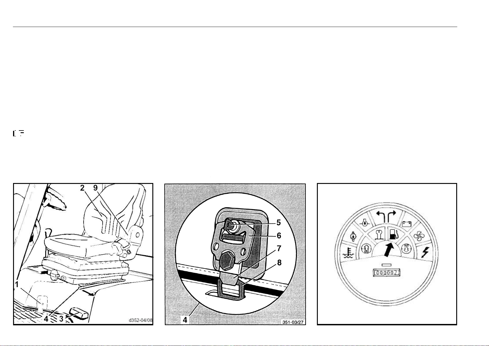
- Push up the lever (9) and fold the backrest (2) forward.
- Pull the lever (4) and slide the seat fully forward.
- Release the engine cover lock (1) by inserting the key (5)
and turning it anti-clockwise as far as possible.
- Lift up the rotary lever (6) and turn anti-clockwise as far as
possible.
- Unhook the tongue (7) from the bracket (8) and lift it.
- Open the engine cover with the grip (3).
NOTE
The engine cover is held in place by a gas-filled strut.
Closing the engine cover
- Close the engine cover with the grip (3).
- Hook the tongue (7) of engine cover lock (4) into the
bracket (8).
- Turn the rotary lever (6) clockwise as far as possible.
- Turn the key (5) clockwise as far as possible and remove
it.
Checking the fuel level
A warning light in the instrument panel lights to indicate a fuel
level of 5.5 litres.
Fill fuel when the light comes on.
351 807 1301.0407
Page 22
Daily checks and servicing before operation Beginning operation
Filling fuel
CAUTION
Stop the engine before filling fuel. No smoking or
naked light when filling fuel. Avoid spilling fuel and
do not allow fuel to contact hot components. Follow the
precautions for handling diesel fuel.
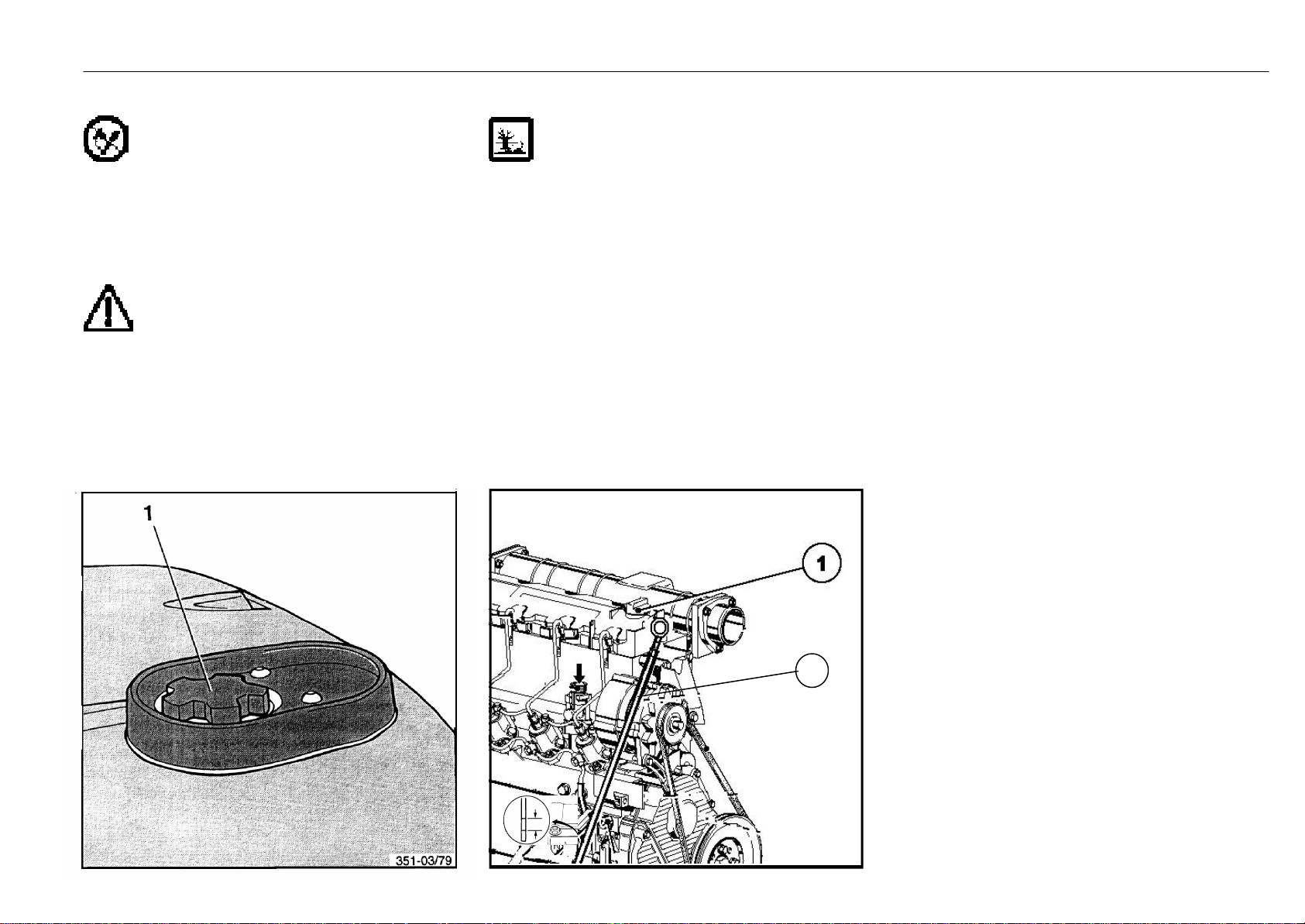
- Open the filler cap (1) on fuel tank and fill clean diesel fuel.
Max. capacity...................................................................... 45.0 L
ATTENTION
Never drive fuel tank empty in order to prevent
malfunction by air in the fuel injection system.
- Install and tighten the tank cap.
351 807 1301.0407
Checking the engine oil level
ATTENTION
Follow the precautions for handling fuels and lubricants.
- Open the engine cover.
- Pull out the oil dipstick (2) at the engine on the left side.
- Clean the dipstick with a clean cloth.
- Reinsert the dipstick completely and pull it out again.
- The oil level should be between both markings.
- If necessary, add oil through the filler opening as far as
the upper marking.
- For this, remove the filler cap (1).
- Refit and tighten the filler cap.
- Close the engine cover.
2
Page 23
Daily checks and servicing before operation Beginning operation
Checking the tyre pressure
ATTENTION
Low inflation pressure reduces tyre service life
and truck stability.
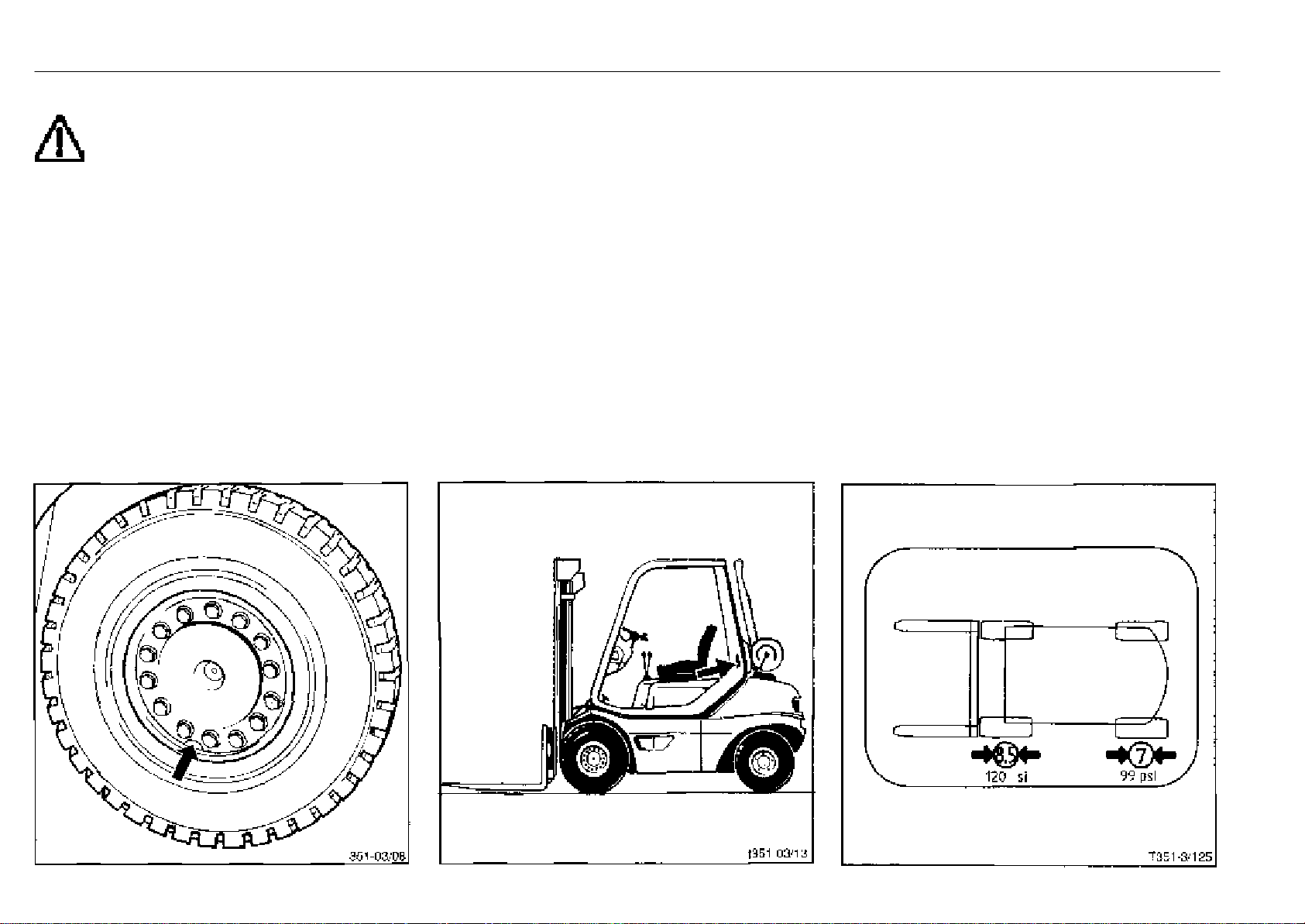
- Check the tyres for specified pressure.
- If necessary, inflate or deflate at the filler valves.
Inflate or deflate the tyres to the pressure specified on the
sticker on the inside of the overhead guard.
Drive axle
Single tyre
H 25 7.00-12/16PR............10 bar
H 25, H 30 27x10-12/14PR........... 7 bar
Twin tyre
H 25, H 30 7.00-12/16PR.............. 7 bar
Steering axle
Single tyre
H 25 6.50-10/10PR.............. 8 bar
H 25, H 30 23x9-10/14PR ............. 7 bar
Example
Tyre pressure sticker
Drive axle
- Single tyre ....................................................................10 bar
- Twin tyre ......................................................................... 7 bar
Steering axle
- Single tyre ...................................................................... 8 bar
351 807 1301.0407
Page 24
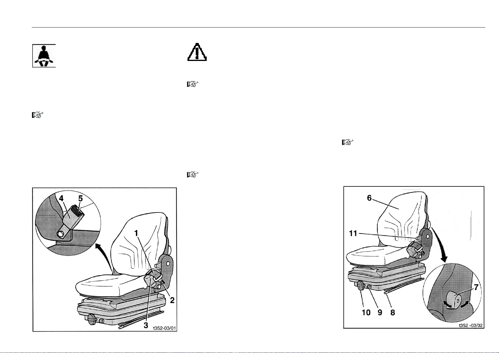
Daily checks and servicing before operation Beginning operation
Applying the seat belt
WARNING
The seat belt must always be applied during the
operation of the truck! The seat belt is only for
securing one person.
Drivercabs with closed, solid doors or bar-type doors
comply with the safety requirements for driver retaining
systems. We recommend the additional use of the seat
belt. The seat belt must be used if the truck is operated with
the doors open or removed.
PVC doors are not considered to be a driver restraint
system.
NOTE
The automatic lock blocks the belt when the truck is tilting
heavily. The belt can then not be pulled out of the retractor.
To unlock the automatic lock, carefully drive the truck off
the side slope.
- Pull the seat belt (1) out of the retractor with a smooth
movement.
- Place the seat belt over the loin area, not over the belly.
- Engage the tongue (2) in the lock (4).
- Check seat belt tension. The belt should be snug on the
body.
351 807 1301.0407
CAUTION
The webbing should not be twisted, stuck or
knotted.
Protect the lock (4) and retractor (3) against foreign
particles, damage and dirt.
NOTE
During operation of the truck (e.g. driving, lifting, etc.) the
operator should sit as far back as possible so that the back
contacts the backrest.
The automatic lock of the retractor allows sufficient freedom of movement on the seat during normal operation of
the truck.
Opening the seat belt
- Press the red button (5) on the belt buckle (4) to disen-
gage the belt.
- Return the tongue (2) back to the roller (3) by hand.
NOTE
A belt which returns too fast can trigger the automatic lock
when the tongue hits the enclosure. The belt can then not
be pulled out with the usual force.
Adjusting the operator seat
- Release the backrest adjuster (11).
- Pull out the knob on the adjusting handwheel (10) and
turn the handwheel to set the cushioning to the weight of
the driver.
The adjustment range from 50 kg to 130 kg is visible at
the weight range indicator (9).
To increase the weight, turn handwheel clockwise.
To reduce the weight, turn handwheel anti-clockwise.
- To adjust the backrest upholstery* (6), move button (7)
until a comfortable sitting position is reached.
Turning the knob anti-clockwise makes the backrest
upholstery arch out.
Turning the knob clockwise returns the backrest upholstery to its original position.
NOTE
Long sitting puts excessive strain on the spinal column.
Prevent strain with regular, light exercising.
* Option
- For a horizontal adjustment of the seat, pull the adjustment lever (8) out.
- Slide the seat in the guide rails either forward or back until
the optimum position in relation to the steering wheel,
accelerator pedals and control levers is obtained.
- Re-engage the lever.
- The adjustment of the backrest is by means of the
backrest adjuster (11).
- Push up and hold the backrest adjuster (11).
- Tilt the backrest forward or back until the position is
comfortable for the driver.
Page 25
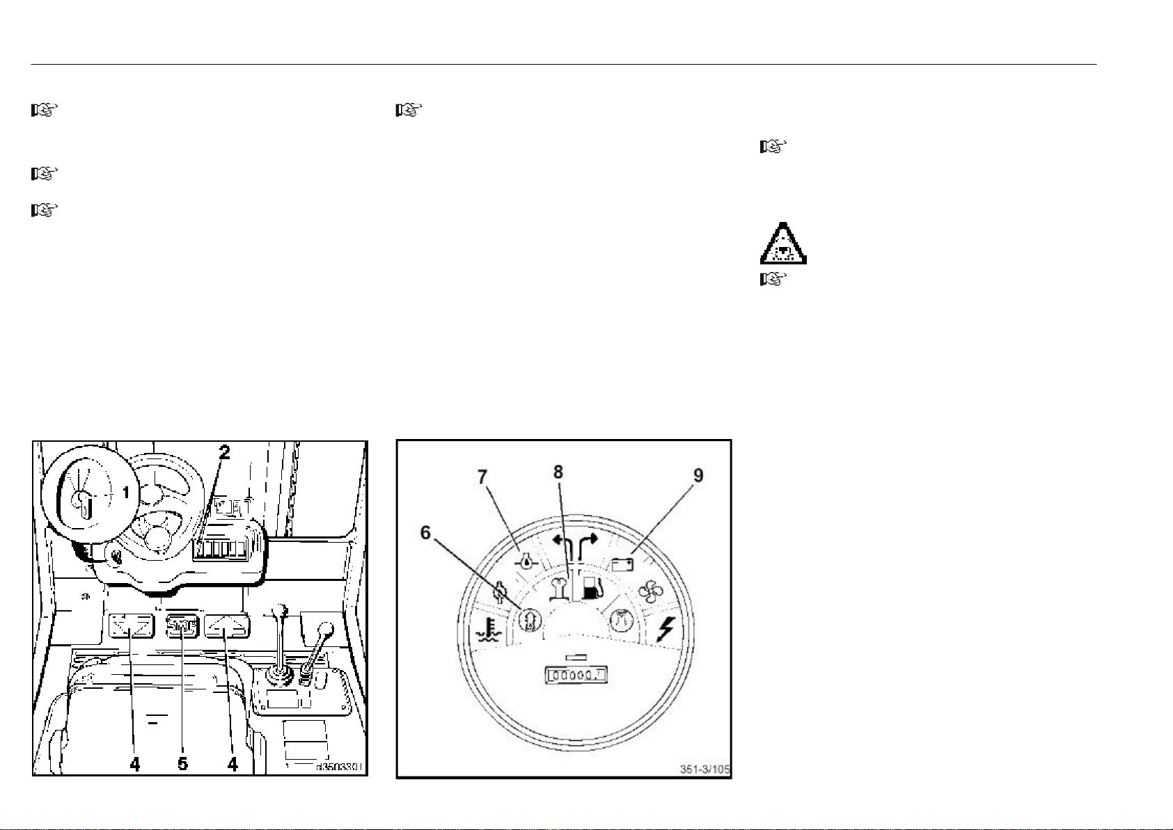
Starting the engine operation
Starting the engine
NOTE
It the lift truck has been out of service for a long period in
an enclosed space, first ventilate well before operating the
electrical system.
NOTE
All control levers must be in neutral.
NOTE
On certain Linde fork trucks (eg with container overhead
guard, swivel seat) the torso clearance is reduced. Therefore only persons with a headroom of 30 mm between the
head and overhead guard should operate this truck.
- Sit down on the driver's seat.
- Apply the seat belt.
- Place both feet on the accelerator pedals (4) without
depressing them (brake pedal (5) locked; engine will
start only with brake pedal locked).
- Insert the switch key (1) into the ignition switch and turn
from the zero position to position I.
The electrical system is turned on.
NOTE
When buzzer* buzzes (fault in soot particulate filter system, version II), conduct a lamp test (see Troubleshooting
Guide (Diesel engine), Possible Cause, Correction). If the
buzzer continues to buzz contact your Linde dealer.
- The engine oil pressure warning light (7)and discharge
indicator light (9) are illuminated red. The preheat indicator* (8) and soot particulate filter warning light* (6) are
illuminated yellow.
- Turn the ignition key to position II. Release the key when
the engine has started.
- If engine does not start, discontinue the starting proce-
dure and repeat after a break in the same manner.
Wait at least 1 minute between starting attempts to spare the
battery. If the engine does not start after the third attempt, refer
to: Engine Troubleshooting Guide.
- The discharge indicator, engine oil pressure and soot
particulate filter* warning lights must extinguish when the
engine is running.
Engine speed is governed automatically, depending on the
load.
NOTE
Refer to regenerating the soot particulate filter if one of the
warning lights (2) illuminates with the variant I soot particulate filter* or if warning light (6) illuminates with the variant
II soot particulate filter*.
WARNING
Do not let the engine run in unventilated enclosed
spaces. Risk of carbon monoxide poisoning!
NOTE
Do not warm up the engine at idle speed.
The engine will reach operating temperature after running
briefly with a moderate load and at various speeds.
351 807 1301.0407
* Option
Page 26
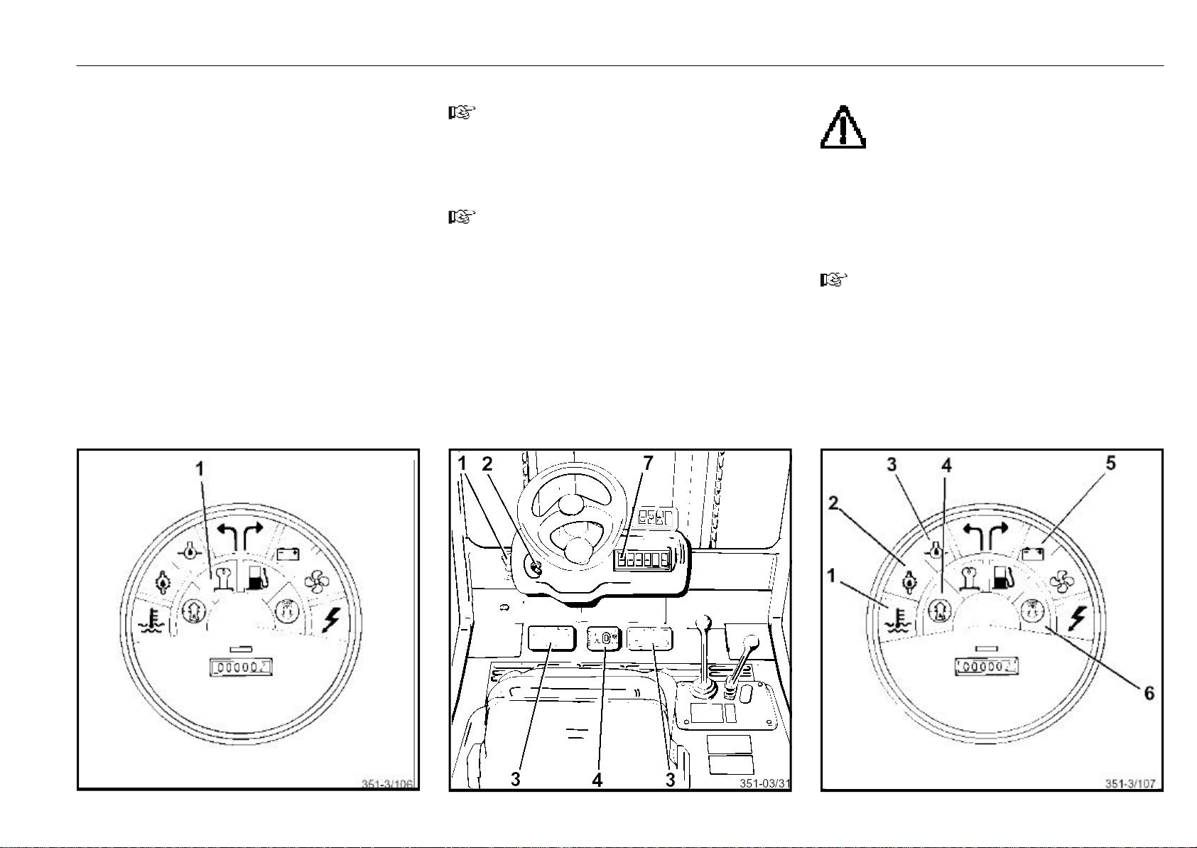
Stopping the engine, malfunctions during operation operation
* Option
Cold start
- Hold the switch key about 15 sec in position I, then turn
it to position II. Release the key when the engine has
started. The yellow preheat indicator (1) will extinguish.
- For further procedures refer to: Starting the engine.
* Option
351 807 1301.0407
*
Stopping the engine
NOTE
Do not stop the engine with a full load.
- Release the accelerator pedals (3).
- Turn switch key (2) to the zero position.
NOTE
The brake engages when the engine is stopped.
- Push up parking brake lever (1).
- Push down stop pedal (4). The stop pedal engages in this
position.
- Remove the switch key when leaving the truck unattended.
Malfunctions during operation
CAUTION
If one of the following indicator lamps illuminates
during operation, the engine must be stopped
immediately and the malfunction eliminated.
(see: Diesel Engine Troubleshooting Guide)
- Coolant temperature warning light (1)
- Hydraulic oil temperature warning light (2)
- Engine oil pressure warning light (3)
- Discharge indicator light (5)
NOTE
The air filter must be serviced if the air filter warning light (6)
comes on during operation.
If the yellow indicator light (7) illuminates with the variant I soot
particulate filter*, the regeneration must be performed within the next hour.
Regenerate the soot particulate filter if the soot particulate
filter warning light (4) illuminates with the variant II soot
particulate filter*.
Page 27
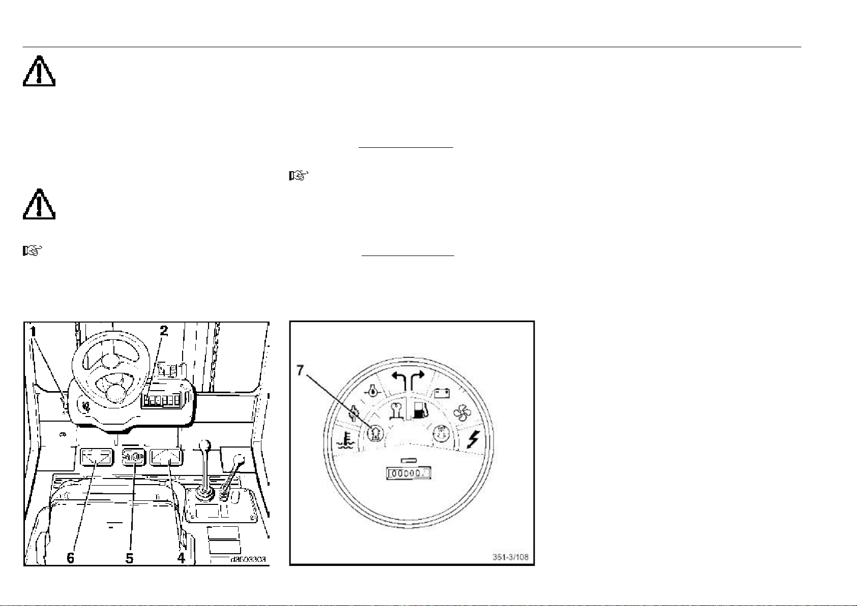
* Option
Driving Operation
CAUTION
Travel on long slopes over 15 % is not allowed as
a rule due to the prescribed minimum brake
applications and truck stability characteristics. Before
driving on steeper slopes, you should consult your authorized dealer. The climbing ability rates given in the data
sheet were derived from the tractive force of the truck and
they apply only for crossing obstacles and for short differences in level.
Always accommodate your driving style to suit the conditions of the roadway (rough surfaces, etc.), especially
hazardous work areas and the load.
CAUTION
When using rear view mirrors it should be noted
that the latter are only provided to monitor the rear
traffic area and that reversing is only allowed with a direct
view in the reverse direction of travel.
NOTE
When the soot particulate filter warning light* (2) with the
variant I soot particulate filter*, or warning light* (7) with
the variant II soot particulate filter* refer to regenerating
the soot particulate filter.
- Start the engine.
- Elevate the forks slightly and tilt the mast back.
- Push the parking brake lever (1) forward. The stop pedal
(5) disengages.
Forward travel
- Depress the right accelerator pedal (4) smoothly. Truck
speed will increase with the pedal stroke.
NOTE
Quick flooring of the accelerator pedal is not recommended as the maximum acceleration rate is regulated automatically.
Reverse travel
- Depress the left accelerator pedal (6). The truck will
reverse at a speed depending on the position of the
accelerator pedal.
Changing the travel direction
- Release the actuated accelerator pedal. The hydrostatic
drive will act as service brake.
- Depress the accelerator pedal for the opposite direction
of travel. The truck will now be accelerated in the selected
direction.
- During travel, keep both feet on the accelerator pedals in
order to be able to control all movements of the truck
easily.
- The accelerator pedals can be operated from forward to
reverse travel directly. The hydrostatic drive will brake the
truck to a standstill and then accelerate it in the opposite
direction.
Stopping
- Slowly release the depressed accelerator pedal. The
hydrostatic travel drive will act as service brake.
- When stopping on gradients during upgrade travel, leave
both feet on the pedals and equalise any drive slippage
due to technical reasons by depressing the pedal slightly,
or
351 807 1301.0407
- depress the brake pedal for a long stop.
- When dismounting from the truck with the engine running, for example, in order to briefly perform some action
in close vicinity to the truck (opening a gate, unhitching a
trailer, etc.), the brake pedal must be depressed and
locked. Open the seat belt. Shut down the engine if
making a long stop. When leaving the truck unattended,
remove the ignition key.
Page 28
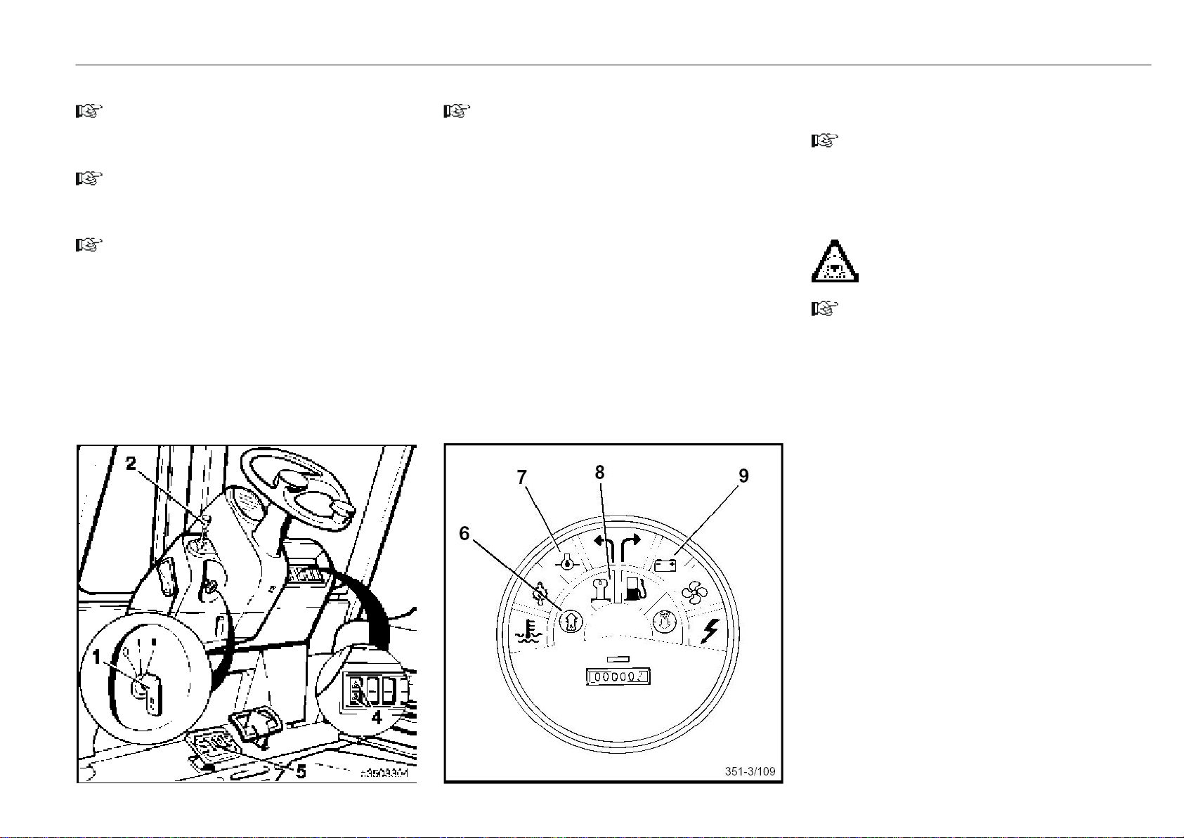
Single-pedal model Operation
Starting the engine
NOTE
It the lift truck has been out of service for a long period in
an enclosed space, first ventilate well before operating the
electrical system.
NOTE
The travel direction control lever (2) on the left-hand side
of the steering wheel and all other control levers must be
in the neutral position.
NOTE
On certain Linde fork trucks (eg with container overhead
guard, swivel seat) the torso clearance is reduced. Therefore only persons with a headroom of 30 mm between the
head and overhead guard should operate this truck.
- Sit down on the driver's seat.
- Apply the seat belt.
- Stop pedal (5) is locked (engine will start only with the
brake pedal locked).
- Insert the switch key (1) into the ignition switch and turn
from the zero position to position I.
The electrical system is now switched on.
351 807 1301.0407
NOTE
When buzzer* buzzes (fault in soon particulate filter system, version II), conduct a lamp test (see Troubleshooting
Guide (Diesel engine), Possible Cause, Correction). If the
buzzer continues to buzz contact your Linde dealer.
- The engine oil pressure warning light (7), discharge
indicator light (9) and the variant II are illuminated red. The
preheat indicator* (8) and the variant II soot particulate
filter warning light* (6) are illuminated yellow.
- Turn the switch key to position II. Release the key when
the engine has started.
- If engine does not start, discontinue the starting proce-
dure and repeat after a break in the same manner.
Wait at least 1 minute between starting attempts to spare the
battery. If the engine does not start after the third attempt, refer
to: Engine Troubleshooting Guide.
- The discharge indicator, engine oil pressure and soot
particulate* warning lights must extinguish when the
engine is running.
Engine speed is governed automatically, depending on the
load.
NOTE
Refer to regenerating the soot particulate filter if one of the
warning lights (4) illuminates with the variant I soot particulate filter* or if warning light (6) illuminates with the variant
II soot particulate filter*.
WARNING
Do not let the engine run in unventilated enclosed
spaces. Risk of carbon monoxide poisoning!
NOTE
Do not warm up the engine in idle.
The engine will attain its running temperature after running
briefly with a moderate load and at various speeds.
* Option
Page 29
Single-pedal model Operation
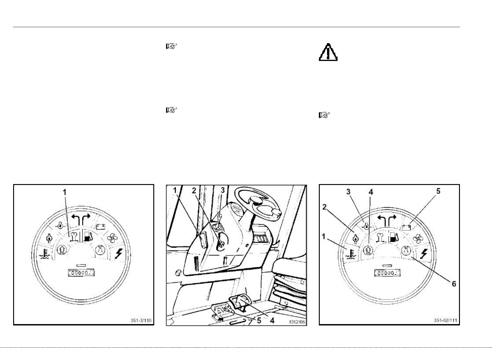
Cold start
- Hold the switch key about 15 sec in position I, then turn
it to position II. Release the key when the engine has
started. The yellow preheat indicator (1) will extinguish.
- For further procedures refer to: Starting the engine.
* Option
*
Stopping the engine
NOTE
Do not stop the engine with a full load.
- Release the accelerator pedal (4).
- Place the travel direction control lever (3) in the neutral
position.
- Turn the switch key (2) to the zero position.
NOTE
The brake engages when the engine stops.
- Set the parking brake lever (1) to the vertical position.
- Depress the stop pedal (5). The pedal will engage in this
position.
- Remove the switch key when leaving the truck unattended.
Malfunctions during operation
ATTENTION
If one of the following indicator lamps illuminates
during operation, the engine must be stopped
immediately and the malfunction eliminated.
(see: Diesel Engine Troubleshooting Guide)
- Coolant temperature warning light (1)
- Hydraulic oil temperature warning light (2)
- Engine oil pressure warning light (3)
- Discharge indicator light (5)
NOTE
The air filter must be serviced if the air filter warning light (6)
comes on during operation.
If the yellow indicator light (7) illuminates with the variant
I soot particulate filter*, the regeneration must be performed within the next hour.
Regenerate the soot particulate filter if the particle filter
warning light (4) illuminates with the variant II soot particulate filter*.
* Option
351 807 1301.0407
Page 30
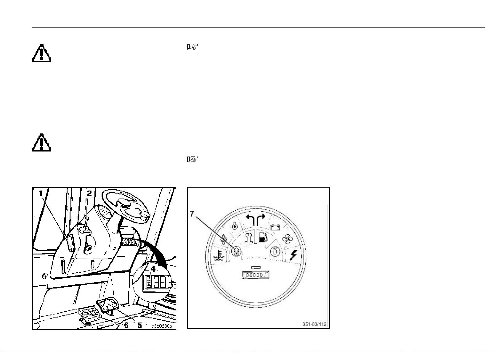
Single-pedal model Operation
Travel
CAUTION
Travel on long slopes over 15 % is not allowed as
a rule due to the prescribed minimum brake
applications and truck stability characteristics. Before
driving on steeper slopes, you should consult your authorized dealer.
The climbing ability rates given in the data sheet were
derived from the tractive force of the truck and they apply
only for crossing ob-stacles and for short differences in
level.
Always accommodate your driving style to suit the conditions of the roadway (rough surfaces, etc.), especially
hazardous work areas and the load.
CAUTION
When using rear view mirrors it should be noted
that the latter are only provided to monitor the rear
traffic area and that reversing is only allowed with a direct
view in the reverse direction of travel.
* Option
351 807 1301.0407
NOTE
Refer to regenerating the soot particulate filter if one of the
warning light (4) illuminates with the variant I soot particulate filter* or if warning light (7) illuminates with the
variant II soot particulate filter*.
- Start the engine.
- Slightly raise the forks and tilt the mast backward.
- Push the parking brake lever (1) forward to release the
stop pedal (6).
Forward travel
- Shift the travel direction lever (2) forward.
- Depress the accelerator pedal (5) gently. Truck speed
depends on how for the pedal is depressed.
NOTE
Quick flooring of the accelerator pedal is not recommended as the maximum acceleration rate is regulated
automatically.
Reverse travel
- Pull back the travel direction control lever (2).
- Depress the accelerator pedal (5) gently. Truck speed
depends on how far the pedal is pushed.
Changing the travel direction
- Release the depressed accelerator pedal (5). The hydrostatic drive will act as service brake.
- Shift the travel direction control lever (2) to the opposite
travel direction.
- Depress the accelerator pedal (5). The lift truck will be
accelerated in the new direction of travel.
- The travel direction control lever (2) can be shifted from
forward travel directly to reverse travel. The hydrostatic
drive will brake the lift truck to a standstill and then
accelerate the truck in the opposite travel direction.
Stopping
- Slowly release the depressed accelerator pedal. The
hydrostatic travel drive will act as service brake.
- When stopping on gradients during upgrade travel, leave
the foot on the accelerator pedal, set the directional lever
(2) to the uphillposition and equalise any drive slippage
due to technical reasons by depressing the pedal slightly,
or
- depress the brake pedal for a long stop.
- When dismounting from the truck with the engine running, for example, in order to briefly perform some action
in close vicinity to the truck (opening a gate, unhitching a
trailer, etc.), the brake pedal must be depressed and
locked, open the seat belt. Shut down the engine if making
a long stop. When leaving the truck unattended, remove
the ignition key.
Page 31
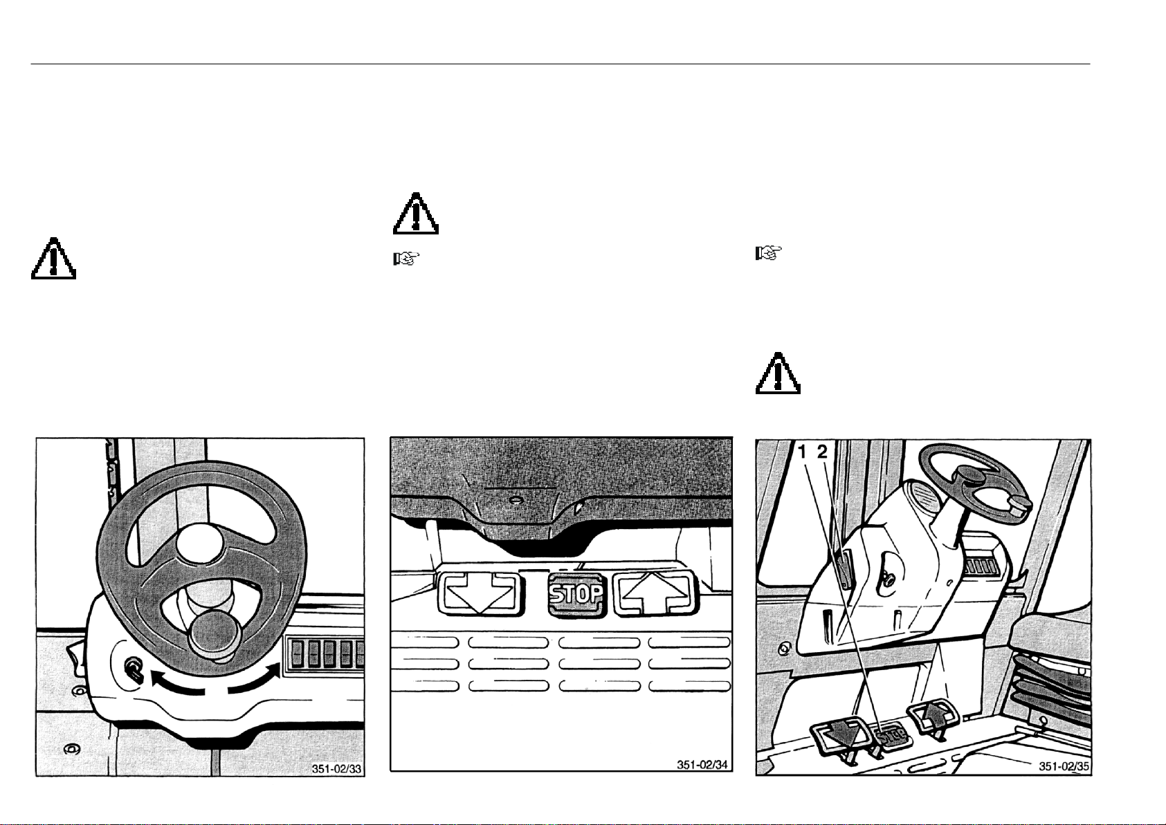
Steering system, braking system Operation
Steering
Due to the hydrostatic power steering, very little effort is
required to turn the steering wheel. This is especially advantageous when stacking in narrow aisles.
- Start the engine and drive the truck.
- Turn the steering wheel from left to right full lock and vice
versa.
WARNING
Contact your distributor if steering becomes hard
or if there is excessive play in the steering wheel.
Do not drive the lift truck with a faulty steering system.
Turning radius
- H 25.........................................................................2290 mm
- H 30 .........................................................................2360 mm
Service brake
- Allow the accelerator pedals to return to the neutral
position. The hydrostatic drive will act as a service brake.
Braking can be controlled from soft to hard braking with
sensitivity by releasing the accelerator pedals slowly or
quickly.
ATTENTION
For emergency braking depress the STOP pedal
located between the accelerator pedals.
NOTE
It is recommended that the operator acquaint himself with
the function and effect of these brakes without a load being
on the truck. Drive on a roadway without traffic at a slow
speed.
Parking brake
The multiple disc brakes are used as a parking brake.
Applying the parking brake:
- Set the parking brake lever (2) to the vertical position.
- Depress the stop pedal (1). The stop pedal will lock in this
position.
Releasing the parking brake:
NOTE
The multiple disc brakes will only be released when the
engine is running.
- Push the parking brake lever (2) forward to disengage the
stop pedal.
WARNING
Contact your authorized distributor if faults or
signs of wear become evident in the braking
system.
Do not drive the truck with a faulty braking system.
351 807 1301.0407
Page 32
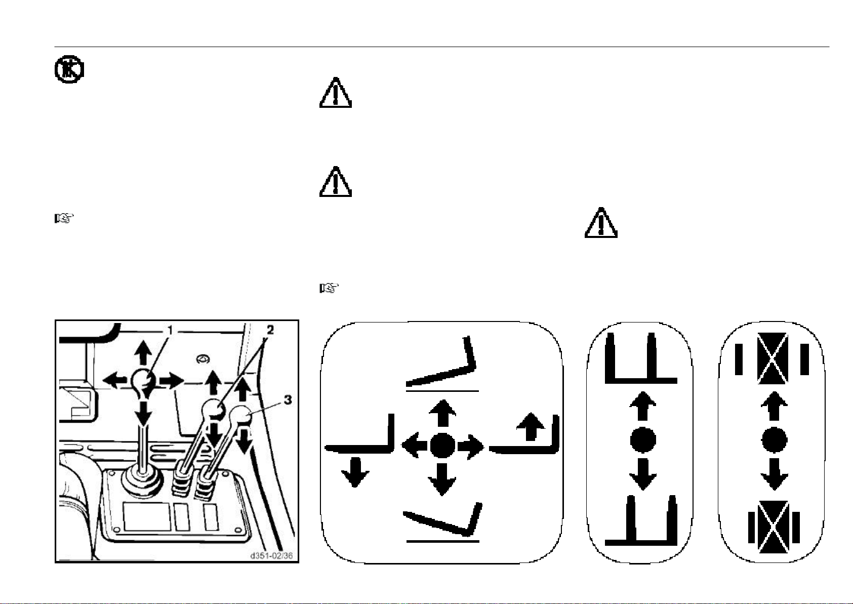
Central-lever control of lifting device and attachments Operation
ATTENTION
Use the lifting device and attachments only for
authorised applications. The operator must be
instructed in the handling of the lifting device and attachments. Observe the maximum height of lift. Do not put your
hands into or step into the mast or in area between the
mast and truck.
Always operate the control levers smoothly and without
jerking.
The lifting, lowering and tilting speed is determined by how
far the control levers are moved.
The control levers return to their neutral position automatically
when released.
NOTE
Note the operating symbols with direction arrows.
Tilting the mast forward
- Push the control lever (1) forward.
Tilting the mast back
- Pull the control lever (1) back.
351 807 1301.0407
Lifting the fork carriage
WARNING
Do not step on raised forks. Increased danger of
falling and being squeezed.
- Push the control lever (1) to the right.
Lowering the fork carriage
- Push the control lever (1) to the left.
CAUTION
The mast and fork carriage can be lowered even
when the engine is shut off.
Operating the attachments
Attachments can be installed as options (e.g. sideshift,
clamp, etc.). Note the working pressure and operating instructions of the attachments.
One or two additional control levers are fitted for their operation.
NOTE
For each attachment, affix a load capacity plate and a
symbol label on the bonnet and a symbol label behind the
appropriate control lever.
Operating the sideshift
- To move the sideshift to the left, push the control lever (2)
forward.
- To move the sideshift to the right, pull the control lever (2)
back.
Operating the clamp
- To open the clamp, push the control lever (3) forward.
- To close the clamp, pull the control lever (3) back.
CAUTION
Attachments not supplied with the truck may only
be employed if your authorised dealer ascertains
that they will not reduce the load capacity and stability of
the truck.
Page 33
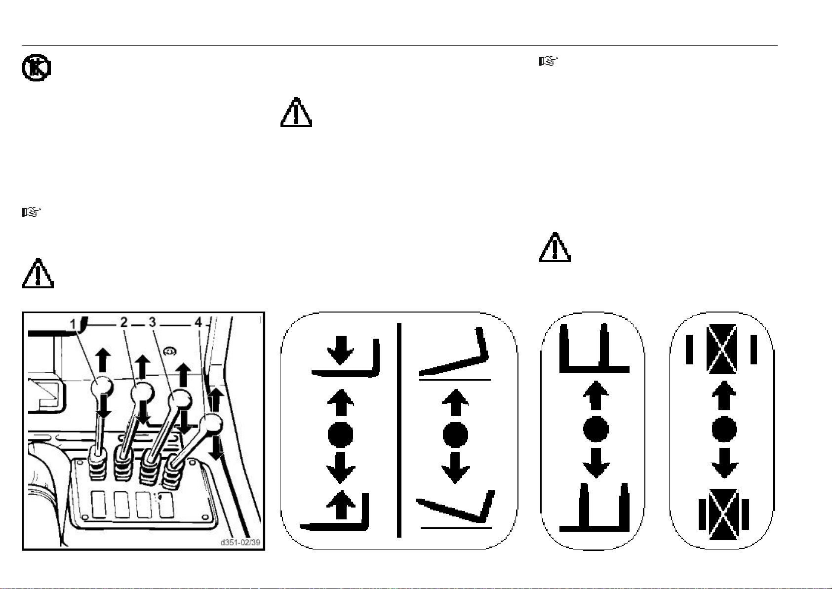
Single-lever control of lifting device and attachments Operation
ATTENTION
Use the lifting device and attachments only for
authorised applications. The operator must be
instructed in the handling of the lifting device and attachments. Observe the maximum height of lift. Do not put your
hands into or step into the mast or in area between the
mast and truck.
Always operate the control levers smoothly and without
jerking.
The lifting, lowering and tilting speed is determined by how
far the control levers are moved.
The control lever returns to its initial position automatically
when released.
NOTE
Note the operating symbols with direction arrows.
Lifting the fork carriage
WARNING
Do not step on raised forks. Increased danger of
falling and being squeezed.
- Pull the control lever (1) back.
Lowering the fork carriage
- Push the control lever (1) forward.
CAUTION
The mast and fork carriage can be lowered even
when the engine is shut off.
Tilting the mast forward
- Push the control lever (2) forward.
Tilting mast back
- Pull control lever (2) back.
Operating the attachments
Additional equipment can be installed as option (e.g. sideshift, clamp, etc.). Observe the working pressure and operating instructions of the attachments.
One or two additional control levers are fitted for their operation.
NOTE
For each attachment affix a load capacity plate on the
engine cover and a symbol label depicting the attachment
behind the appropriate control lever.
Operating the sideshift
- To move the sideshift to the left, push the control lever (3)
forward.
- To move the sideshift to the right, pull control lever (3)
back.
Operating the clamp
- To open the clamp, push the control lever (4) forward.
- To close the clamp, pull the control lever (4) back.
CAUTION
Attachments not supplied with the truck may only
be employed if your authorised dealer ascertains
that a safe operation is assured in respect to load capacity
and stability.
351 807 1301.0407
Page 34
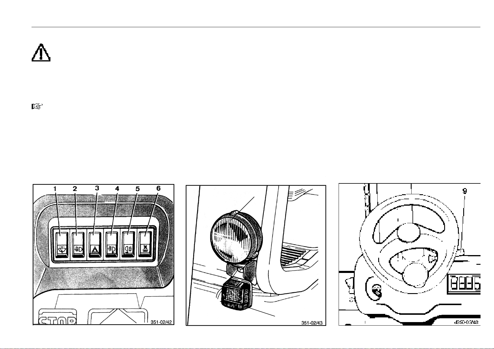
Windscreen wipers*, lighting*, working lights*, directional indicators
* Option
*
Operation
Installation of additional equipment
ATTENTION
Electrical additional equipment (lights, seat heat-
er etc.) should be connected to the free connectors of the cable loom provided for this purpose.
Further connections beyond this anticipated range are
only permitted after contacting Linde.
Only qualified skilled persons who observe the applicable
rules and use appropriate material should carry out these
activities.
NOTE
The switches on the console can be arranged in a different
order, depending on the model. Please note the switch
symbols.
Switching on the front working lights
The working lights are turned on and off with toggle switch (1).
Switching on the rear working lights
The working lights are turned on and off with toggle switch (2).
351 807 1301.0407
Switching on the lighting (7)
- Depress the light switch (3) to the intermediate position
to switch on the side marker lights and license plate light.
- Depress the light switch to switch on low beam.
Switching on the hazard warning light
- Depress the hazard warning light switch (4).
Turning on the front windscreen wiper
- Depress switch (5) to the intermediate position to operate
the front wiper intermittently.
- Depress switch (5) fully to operate the front wiper continuously.
7
Turning on the rear windscreen wiper
- Depress switch (6) to the intermediate position to operate
the rear wiper intermittently.
- Depress switch (6) fully to operate the rear wiper continuously.
Switching on the directional indicators
- Move the directional indicator switch (9) on the steering
column forward or back to operate the directional indicators (8) on the left or right.
8
Page 35
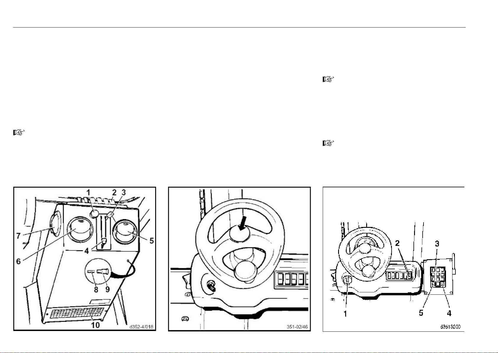
Water heater
*
, horn, data logger* Operation
Controls
The fan is turned on with the fan switch (1); the air flow can
be regulated in three stages.
Shift lever (3) for temperature control
- up for less heat,
- down for more heat.
Shift lever (4) for air intake
- down for air intake through opening (10) in the cabin,
- up for air intake from outside.
The swivelling air outlets (5, 6 and 7) and the distributor (2)
can be opened separately. Depending upon the position of
lever (3), either warmed or non-warmed air flows out of all
outlets and the distributor.
NOTE
When lever (3) is in the topmost and lever (4) in the
bottommost position, fresh air from outside flows in through
the outlets and distributor. If you want to prevent outside
air from entering, shift lever (4) up.
All controls (except the fan switch) can be set to any
intermediate position.
Fan motor fuse
- Screw the retainer (9) out of the housing and remove
along with the fuse (8) (8 A).
Operating the horn
When operating at blind corners and junctions, a horn serves
as warning signal.
- Press the horn button on the steering wheel to sound
the horn.
Data Logger*
The Data Logger has a key panel with 12 buttons. By allocating
a 5-digit PIN number to the driver it is assured that only
authorised personnel may operate the fork truck. The truck is
started by entering this PIN number.
Start the truck:
- Turn the switch (1) clockwise to switch position I.
The two indicator lights (2) come on.
- Enter the 5-digit PIN number at the key panel (3).
- Confirm by pressing the "ENT" button (4).
- Turn the switch (1) fully clockwise to start the truck.
NOTE
If the truck does not start at first, the starting procedure
can be repeated until the switch is returned to the zero
position and the PIN number is no longer stored.
Stop the truck:
- Press the CLR button (5) in the key panel (3).
- Turn the switch (1) counterclockwise as far as possible.
The engine is shut off.
The two green indicator lights (2) extinguish again.
NOTE
If the driver's seat is left for a longer period (about 3 min),
the truck shuts off automatically. To resume operations,
restart the truck.
* Option
351 807 1301.0407
Page 36
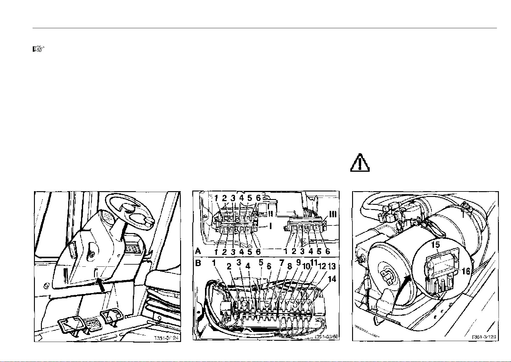
Fuses Operation
* Option
Check the fuses, replace if necessary
NOTE
For the protection of the electrical system, up to 3 fuse
boxes can be installed in the console, depending on the
model. The fuse boxes can be accessed by lowering the
cover on the underside of the console (arrow) after first
removing 4 screws.
- Remove the cover of the appropriate fuse box.
The version B fuses (8 A) protect the following circuits:
1 Composite instrument
2 Horn
3 Directional control, single-pedal model*
4 Wiper motor*
5 Front working light*
6 Front working light*
7 Front working light*
8 Rear working light*
9 Front dip beam, left*
10 Front dip beam, right*
11 Front and rear left position light, tail light*
12 Front and rear right position light, tail light*
13 Directional indicators*
14 Hazard warning flasher*
351 807 1301.0407
The version A fuses protect the following circuits:
Note the numbers or letters on the fuse boxes and in the cover
(1 = A left).
Fuse box I: standard equipment
1 Starter relay (F2) ...............................................................5 A
2 Composite instrument (F3)............................................5 A
3 Electronic ignition, fuel shutoff valve (F4)..................30 A
4 Horn and aux. relay, seat heater*, fine filter*,
terminal 15 (F5) ..............................................................10 A
5 Single-pedal model, reversing signal (F6).................5 A
6 Oil pump (F7) ....................................................................5 A
Fuse box* II: lighting
1 Left dip beam (5F5) .......................................................10 A
2 Right dip beam (5F6) ....................................................10 A
3 Left side marker light (5F7)............................................5 A
4 Right side marker light (5F8).........................................5 A
5 Main lighting fuse, terminal 15 (5F9) .........................20 A
6 Main lighting fuse, terminal 30 (5F10).......................15 A
Fuse box* III: windscreen wiper, working lights, heater
2 Working light, revolving light,
flashing light (9F13)......................................................15 A
3 Working light (9F12) ......................................................15 A
4 Working light (9F11) ......................................................15 A
5 Rear screen wiper (9F5)...............................................10 A
6 Front screen wiper (9F4) ..............................................10 A
Another MTA fuse in the engine compartment protects the
following electric circuits:
- Open the bonnet, remove the covers (15).
Main fuse (F1) (16) for complete electrical system .......50 A
Heater (9F14) ........................................................................50 A
ATTENTION
Only use genuine Linde fuses.
Page 37
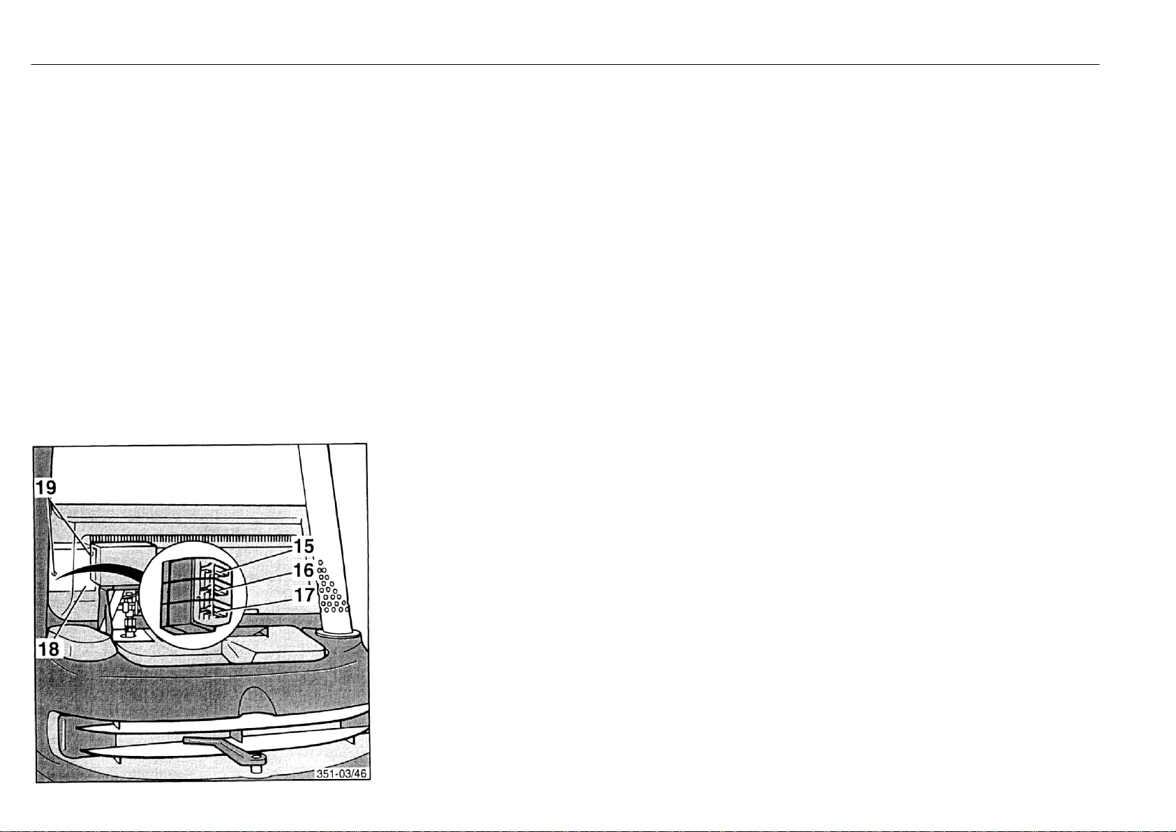
Fuses, soot particulate filter system
* Option
The fuses for the variant II soot particulate filter system* are
located in the fuse box behind the battery compartment cover.
- Remove the battery compartment cover.
- Remove the mounting screws (19) and take off the cover
(18).
15 Metering pump solenoid valve (7F15) .........................5 A
16 Fan motor (7F17)............................................................20 A
17 Main fuse (7F16).............................................................30 A
*
Operation
351 807 1301.0407
Page 38
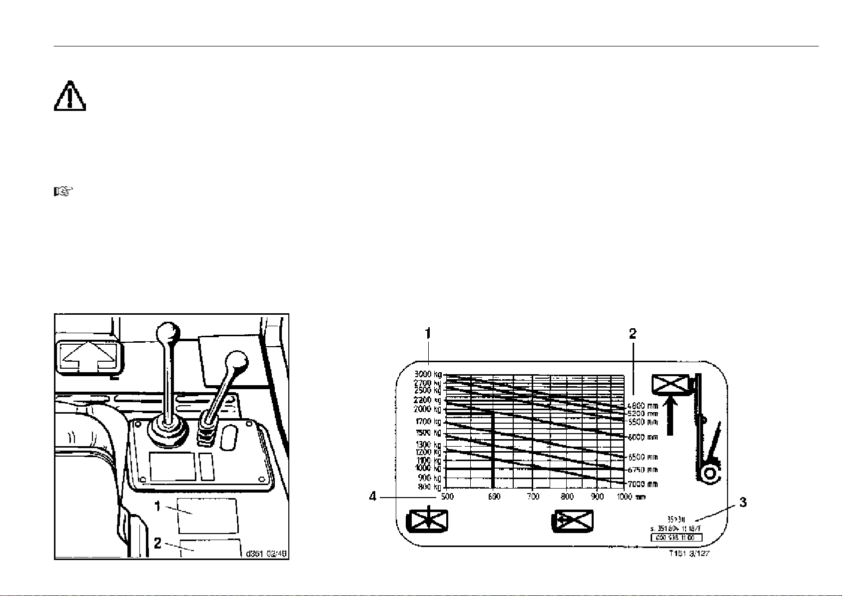
Before lifting a load Operation
Before lifting a load, check the capacity diagram (1) on the
engine cover.
WARNING
When attachments are fitted, check the capacity
plate (2) for that equipment.
Figures stated in the capacity diagram or plate apply to
compact and regular loads and must not be exceeded, as
this will reduce the stability of the fork truck and the
strength of the forks and mast.
The maximum capacity is determined by the height of lift and
the load centre distance.
NOTE
Check the load capacity limits and contact your authorized
distributor before transporting
- off-centre or swinging loads,
- loads with the mast tilted forward or the load not near the
ground,
- loads beyond the centre of gravity,
- before operating attachments,
- loads at wind force 6 and higher.
351 807 1301.0407
Example
Load centre distance .................................................. 600 mm
Height of lift .................................................................6000 mm
- Follow the vertical line for a load distance of 600 mm to
where it intersects the line for a height of lift of 6000 mm.
- Read to the left of the point of intersection of the horizontal
line for max. permitted load.
- Max. weight here is ...............................................1900 kg.
Proceed accordingly for other lift heights and load centre
distances. Values ascertained apply to even distribution of
the load on the forks.
1 Max. weight of loads in kg
2 Height of lift in mm
3 Fork truck type with rated capacity
4 Distance of load centre from fork-face in mm
Page 39
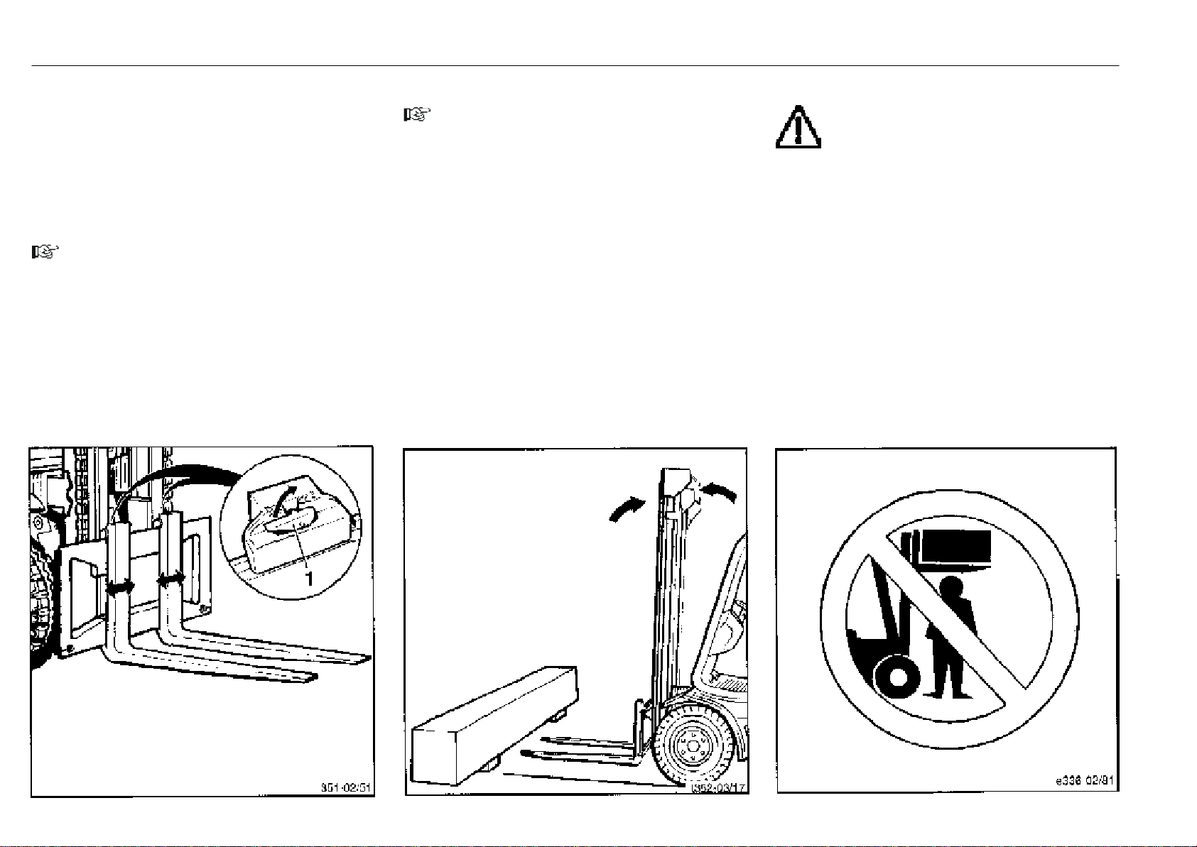
Loading Operation
Adjusting the fork spread
- Raise the fork quick-release levers (1).
- Move the forks further apart or closer together depending
to the size of the load to be lifted. Make sure that both forks
are equally distant from the truck centre.
- Allow the quick-release levers to engage in a notch on the
fork carriage.
NOTE
The load centre should be in the centre between the forks.
Loading
NOTE
The loads must be picked up so that they do not project
beyond the loading area of the truck, and will not fall over
or off.
- Approach the load to be lifted carefully and as accurately
as possible.
- Put the mast to the vertical position.
- Lift or lower the fork carriage to the required height.
- Carefully drive the truck forward under the centre of the
load until the load contacts the fork-face, if possible, while
taking care not to dislodge adjacent loads.
- Lift the fork carriage until the load is clear of the ground.
- Reverse the lift truck until the load is clear.
- Tilt the mast back.
WARNING
Do not stand under an elevated load. Drive the fork
lift truck only with the load lowered and the mast
tilted back.
351 807 1301.0407
Page 40
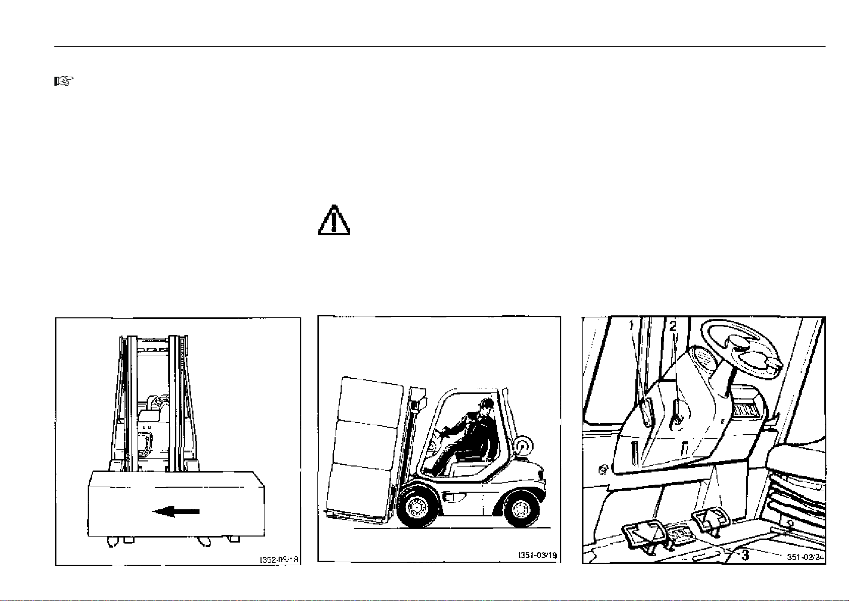
Travel with a load, unloading Operation
Travel with a load
NOTE
When sending goods by freight, the consignor must load
and fasten, if necessary, the transported goods safely. Pay
attention to proper stacking and make sure that the packaging, pallets, etc. are not damaged. The freight carrier is
responsible for the safe handling.
- Do not drive with the load shifted to the side (e.g. with
sideshift).
- Transport the load near the ground.
- Always travel with the load facing uphill on inclines, never
travel or turn across the slope.
- If visibility is reduced, work with a guide.
- Operate the lift truck only in reverse if the load being
transported is stacked so high as to obstruct visibility in
the direction of travel.
351 807 1301.0407
Unloading
- Carefully approach the racking receiving the load.
- Lift the fork carriage to the required height.
- Put the mast into vertical position (load horizontal).
- Carefully drive into the racking.
- Carefully lower the load onto the racking.
- Reverse the lift truck
WARNING
Never park the truck and leave it unattended with
the load raised.
Parking the lift truck
- Deposit the load or lower the fork carriage.
- Tilt the mast slightly forward so that the forks touch the
ground.
- Set the parking brake lever (1) to the vertical position.
- Depress the stop pedal (3). The stop pedal will lock in this
position.
- Stop the engine.
- Remove the switch key (2).
Page 41
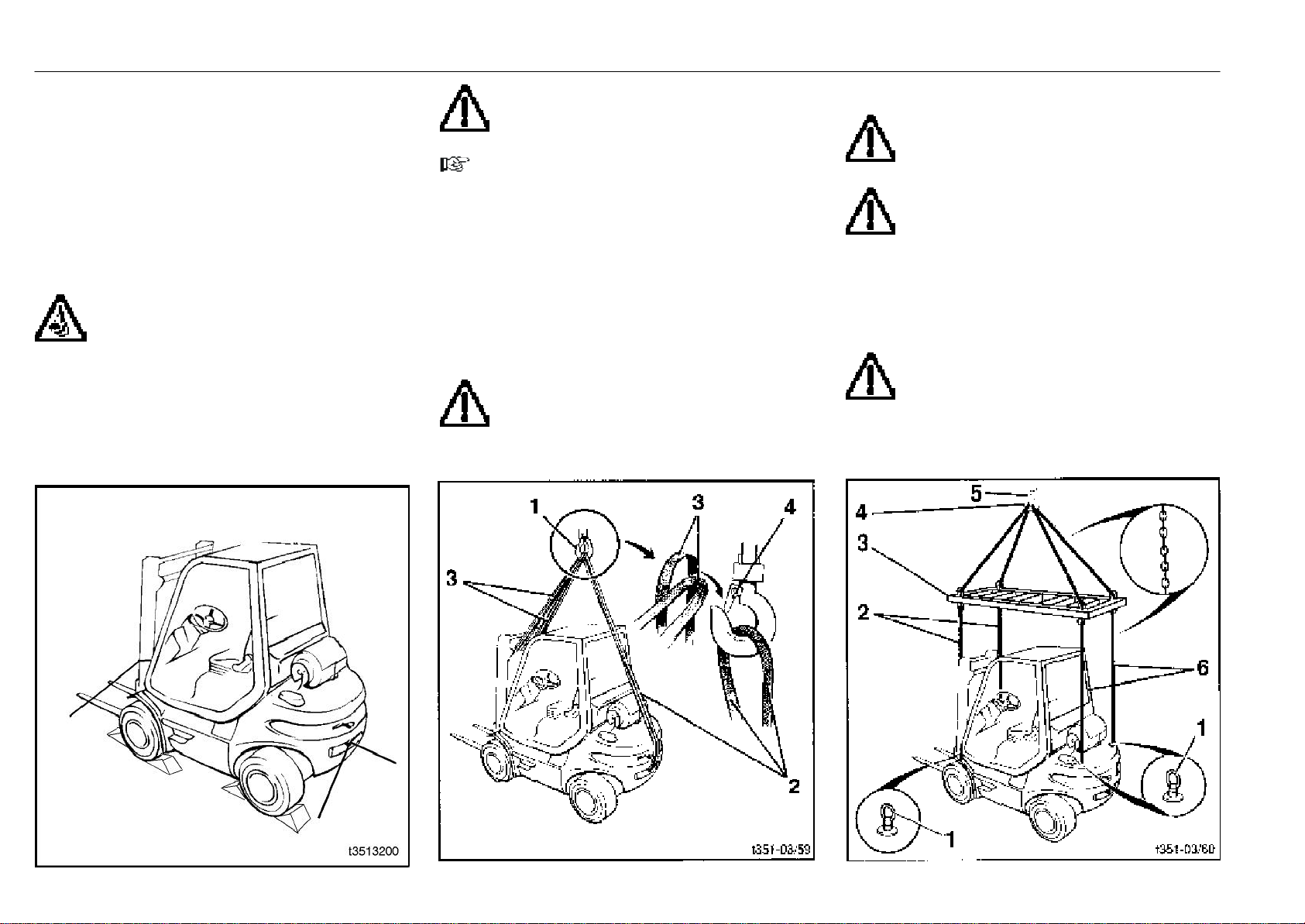
Transport, hoisting the truck Operation
* Option
Transport with lorry or low-bed semi-trailer
- Lower the mast.
- Operate the parking brake.
- Chock the truck.
- Lash the truck down.
Hoisting the truck with a crane
DANGER
When loading the truck by crane
make sure no persons are within the
working range of the crane!
Do not step under the elevated load!
CAUTION
Only use lifting slings and crane of sufficient
capacity. See the manufacturer's plate for the
truck weight.
NOTE
To hoist with a crane, attach the lifting slings at the points
provided. The lifting points on your truck are not labelled
extra.
- Attach the lifting sling (2) (3000 kg carrying capacity
minimum) to the tow bolt.
- Lock the tow bolt.
- Attach the lifting sling (3) (3000 kg carrying capacity
minimum) to the cross member on the outer upright of
the mast.
Use edge protections on sharp edges.
- Attach all the ends to the crane hook (1).
CAUTION
After inserting the slings into the crane hook, the
safety lock (4) must close. When the truck is
hoisted, the slings must not rub against the sides of the
overhead guard and any attachments fitted.
Hoisting the truck with the eyebolts
CAUTION
Only use a slifting sling and acrane with a suffi-
cient capacity. See the manufacturer's plae for the truck.
ATTENTION
The truck may be hoisted with the eyebolts (1)
only if the appropriate lifting equipment (3) is used
with which the chains (2, 6) lead straight up from the
eyebolts (1).
- Hook the chains (6) (minimum capacity 3000 kg) into the
eyebolts (1) on the counterweight.
- Hook the chains (2) (minimum capacity 3000 kg) into the
eyebolts (1) on the frame.
ATTENTION
After attaching the lifting slings to the crane
hook (4), the hook safety (5) must close.
The lifting gear must not touch the overhead
guard and any attachments fitted.
*
351 807 1301.0407
Page 42
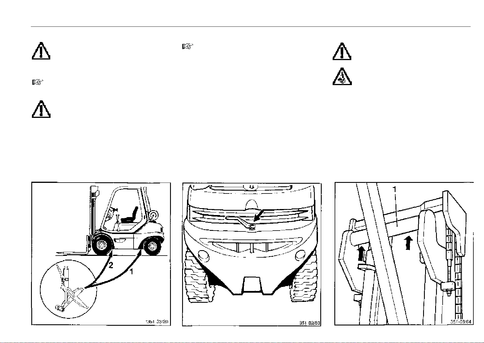
Changing wheels, trailer coupling, mast removal Operation
Changing wheels
CAUTION
Only use a jack with a sufficient lifting capacity.
The minimum capacity should be 3600 kg.
- Loosen the fasteners of the wheel to be changed.
- Locate the jack.
NOTE
Locate the jack only at the front corner of the frame (2) and
under the counterweight (1).
CAUTION
The truck may only be raised at these locations on
the left and right side.
- Raise the truck with the jack until the wheels are clear.
- Secure the truck with wooden blocks under the frame or
counterweight.
- Remove the wheel fasteners and change the wheel.
- Install the wheel fasteners and tighten them by hand.
- Lower the truck.
- Tighten all wheel fasteners to a torque of:
front.............................................................................195 Nm
rear..............................................................................400 Nm
351 807 1301.0407
Trailer coupling
NOTE
The trailer coupling should only be used to tow light trailers
inside the plant area (Observe the applicable accident
prevention guidelines and VDI 3973.)
- Turn the lever 90o degrees to the rear and then raise the
tow bolt.
- Place the towbar in the coupling sleeve.
- Press down the tow bolt against spring pressure, turn
90degrees and let engage in the safety.
Mast removal
ATTENTION
Attach the lifting sling to the top cross member (1)
of the outer upright of the mast.
CAUTION
Do not step under the elevated load.
The mast may only be dismantled by your distributor's skilled
staff.
Page 43
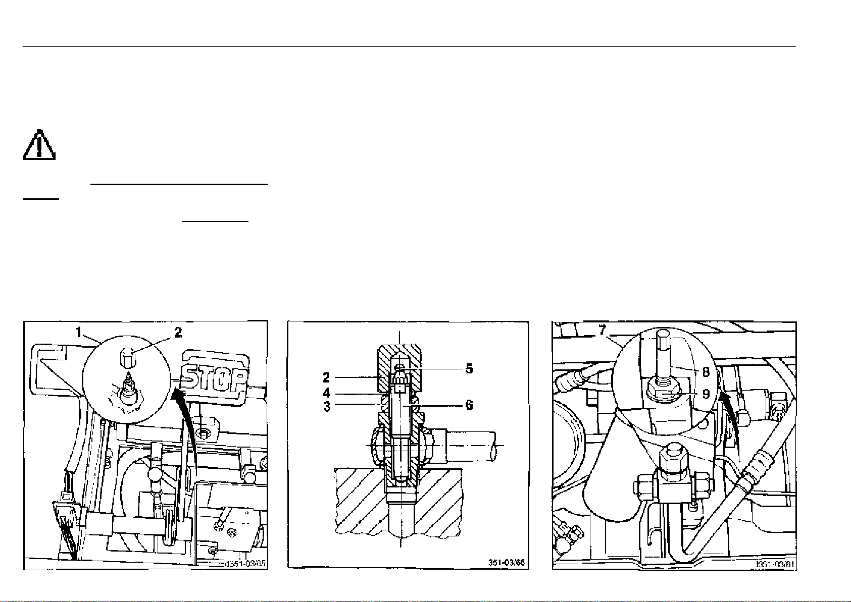
Towing instructions Operation
Towing
Should it become necessary to tow the truck, with the by-pass
device it is possible
- to by-pass the hydraulic oil circuit (7), and
- to release the disc brakes in the compact axle (1).
CAUTION
The truck cannot be braked now.
The tractor used to tow the fork truck
must have sufficient tractive and braking
power for the unbraked towed load.
Towing the truck is only allowed with a rigid connection (tow
bar).
Towing procedure
- Lower the load so far that the forks do not scrape on the
ground during towing.
- Deposit the load.
- Secure the tractor (observe sufficient tractive and braking
power) with tow bar to towing pin of lift truck.
- Place chocks (wedges) behind the wheels on the slope
side.
Releasing the multiple disc brake
- Open the bonnet.
- Remove the floor plate.
- Unscrew the cap nut (2) in the centre under the pedal
console and remove the seal ring (4).
- Screw in the threaded pin (6) as for as possible and
tighten to 10 Nm.
- Lock the threaded pin with nut (3). Tighten the nut to 25 Nm.
- Apply about 4 shots of grease with a grease gun through
the lubricating nipple (5) until the brake is clear.
Opening the hydraulic by-pass valve
- Remove the front cover on the truck.
- Loosen the locknut (9) (18 or 19 mm) on the housing by
turning it anti-clockwise with a socket.
- Loosen the setscrew (8) with 10 mm socket by 3 turns.
- Lock the setscrew with the locknut (9). Torque the nut to
60 Nm.
After towing
- Chock the wheels on the slope side.
- Loosen locknut (9).
- Screw in setscrew (8) (10 mm) and torque to 20+5 Nm.
- Lock setscrew by tightening the locknut (9) to 60 Nm.
- Install the front cover on the truck.
Re-establishing braking power
- Loosen locknut (3).
- Loosen threaded pin (6).
- Lock threaded pin with nut (3), torque to 25 Nm.
- Fit the sealing ring (4).
- Screw on cap nut (2) and tighten to 30 Nm.
- Install the floot plate and close the bonnet.
Check brake function after completing repairs.
351 807 1301.0407
Page 44
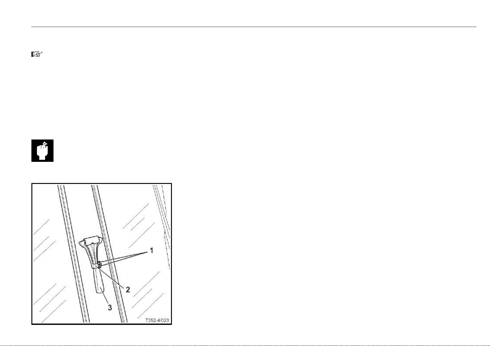
Emergency exit for trucks with rear windscreen Operation
Emergency exit for trucks with rear windscreen
NOTE
If the truck is fitted with a front and rear windscreen, it may
not be possible to dismount at the side if the truck breaks
down in a narrow aisle. In case of acute danger, the driver
can leave the truck through the rear window. To do so, the
driver must destroy the window with an emergency hammer.
- Pull the cotter pin (1) out of the mounting (2) at the right
rear support of the overhead guard.
- Take the hammer (3) out of the mounting and cautiously
break the window pane.
- Remove any pane remnants
CAUTION
Risk of injury.
- Carefully dismount from the truck through the rear win-
dow.
351 807 1301.0407
Page 45
Taking the truck out of operation Maintenance
If the truck is taken out of operation for over 2 months, it must
be parked in a well ventilated, frost-free, clean and dry room
and the following measures must be carried out.
Measures before taking the truck out of operation
- Thoroughly clean the truck.
- Fully elevate the fork carriage several times, tilt the mast
forward and back and, if fitted, operate the attachment
several times.
- Lower the forks on a support until the chains are slack.
- Check the hydraulic oil level and add oil, if needed.
- Add diesel fuel.
- Apply a thin film of oil or grease on all unpainted mechanical parts.
- Lubricate the truck.
- Check the condition and electrolyte level of the battery.
Coat the battery terminals with non-acidic grease. (Follow the instructions of the battery manufacturer.)
- Spray all open electrical contacts with a suitable contact
spray.
ATTENTION
Block up the truck so that all wheels are clear of
the ground. This will prevent tyre deformation.
Putting the truck back into operation
- Thoroughly clean the truck.
- Lubricate the truck.
- Coat the battery terminals with non-acidic grease.
- Check the condition and electrolyte level of the battery.
- Check the engine oil for condensation water and change
the oil, if necessary.
- Check the hydraulic oil for condensation water and change
the oil, if necessary.
- Perform the same services as for commissioning.
- Take the truck into service.
General information
Your truck will remain operational only if the maintenance
and checks are carried out regularly and according to the
information and instructions in the operating manual. The
maintenance may only be performed by qualified authorized
personnel. This work can be carried out by your authorized
distributor under a service contract.
If you wish to do the work yourself, we recommend that the first
three customer service checks be carried out by your distributor's mechanic in the presence of the responsible mechanic in your workshop, so that your staff can receive the appropriate instruction.
For all servicing, the truck must be placed on a level surface
and the wheels secured.
Stop the engine and remove the switch key.
When working on the truck with the fork carriage and mast
elevated, secure them against inadvertent lowering.
For work on the front end of the truck, secure the mast against
tilting back.
No changes, particulary no modifications and additions, may
be made to the truck without the approval of the manufacturer.
ATTENTION
Missing or damaged plates and/or adhesives must
be replaced. For location and oder no. refer to
Parts catalogue.
Perform a functional check and trial run after every servicing.
351 807 1301.0407
NOTE
Do not use plastic foil as this enhances the formation and
collection of condensation water.
NOTE
If the vehicle is to be taken out of operation for over 6
months, contact your authorized dealer for further measu-
res.
NOTE
When operating the truck under extreme conditions (i.e.
extreme heat or cold, intensive dust concentration, etc.),
the intervals given in the maintenance schedule should be
reduced accordingly.
ATTENTION
Follow the precautions for handling fuels and lubricants.
Page 46
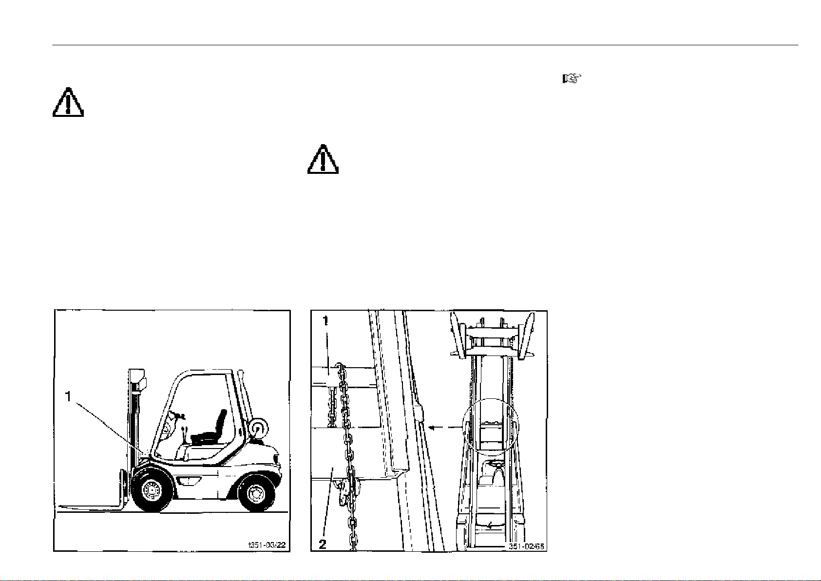
Mast types Maintenance
Work on the mast and on the front part of the
truck
WARNING
Before attempting to carry out repairs or adjust-
ments on the raised mast and fork carriage,
ensure that the following safety procedures are carried
out!
These safety measures are only sufficient for general
maintenance on your truck (tests and lubrication). For
repairs (e.g. replacement of chains or lift jack), further
additional safety measures must be applied. Please contact your authorized distributor.
Securing the mast against tilting back
To prevent the lift mast from tilting back accidentally, insert a
800 mm long 120 x 120 mm hardwood block (1).
351 807 1301.0407
Standard mast
FUNCTION
When the inner mast is lifted, the chain idler wheel is also
moved upward thereby raising the fork carriage at a 2 : 1
speed ratio.
Securing the raised standard mast
WARNING
Use a suitable chain for the particular lifting mast.
Do not exceed the maximum height of lift.
- Raise the mast.
- Fasten the chain around the cross member of the outer
upright (1) and the cross member of the inner mast (2).
- Lower the inner mast until it is held by the chain.
Duplex mast
NOTE
The advantage of this mast version is that the special free
lift height can be used even in spaces with a low ceiling
(cellars, wagons, ships).
FUNCTION
The fork carriage is raised to the special free lift height by the
centre lift cylinder via the chain guide roller. It moves at twice
the rate of the centre cylinder.
The inner mast and the fork carriage is then raised together
by both the secondary exterior lift cylinders.
The centre cylinder is mounted within the extendible inner
mast.
Page 47
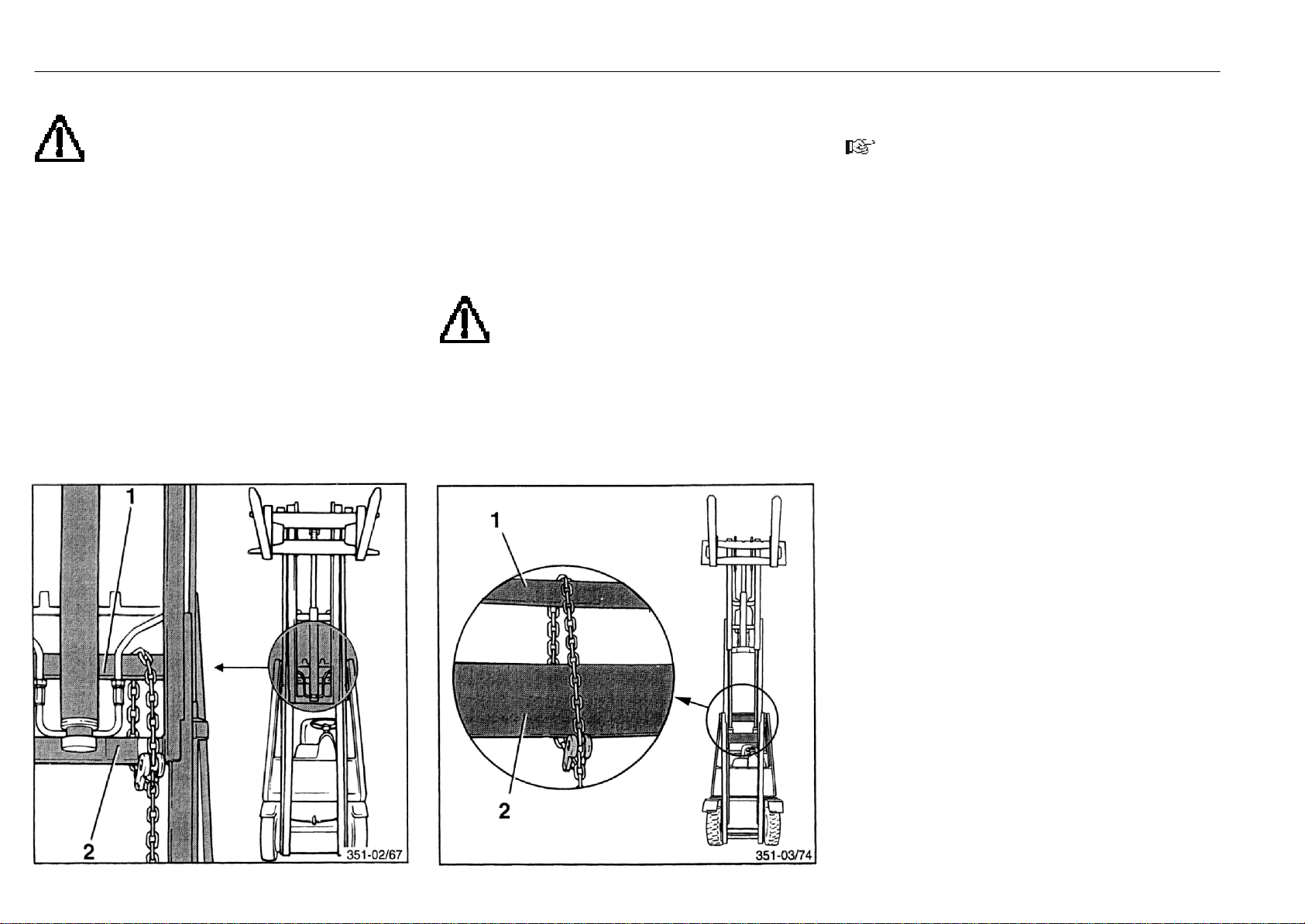
Mast types Maintenance
Securing the raised duplex mast
WARNING
Use a suitable chain for the particular lifting mast.
Do not exceed the maximum height of lift.
- Lift the mast.
- Fasten chain around the cross member of outer upright
(1) and the cross member of inner mast (2).
- Lower the inner mast until it is held by the chain.
- Fully lower the fork carriage.
Triplex mast
FUNCTION
The fork carriage is raised to the special free lift height by the
centre cylinder via the chain guide roller. Then the two lift
cylinders raise the inner mast.
When the inner mast is fully extended, two further lift cylinders
raise the centre mast, which is raised together with the inner
mast and fork carriage.
The centre cylinder is mounted on the extendible centre
mast.
Securing the raised triplex mast
WARNING
Use a suitable chain for the particular lifting mast.
Do not exceed the maximum height of lift.
- Raise the mast.
- Fasten the chain around the cross member outer mast
(1) and the intermediate mast (2).
- Lower the mast until it is held by the chain.
- Fully lower the fork carriage.
Checks and services after the first 50 service hours
NOTE
A description of the services can be located in the index.
- Replace the engine oil
- Replace the engine oil filter
- Check the tension and condition of alternator and fan Vbelt
- Check and adjust valve clearance
- Check the air intake and exhaust pipes for leaks
- Check parking brake
- Tighten wheel fasteners
- Check tyres for damage and foreign objects
- Check tyre inflation pressure
- Check hydraulic system, compact axle, pumps,
valves, and lines for leaks
- Renew the pressure, suction and breather filters in the
hydraulic system
- Check battery condition, electrolyte level and specific
gravity
- Check engine mounting for condition and tightness
- Check mounting of engine, overhead guard, steering axle
and wheel drive for tightness
- Clean and grease the steering axle
- Grease the mast and tilt cylinder pivots
- Check the mast, lift chains and stops for condition,
mounting and operation
- Check the pre-tension of double hoses if attachments are
fitted
- Clean, adjust the lift chains and spray with chain spray
- Check electric cables, cable connectors and connections for condition and tightness
- Drain the fuel system water pre-separator
- Clean the air filter
- Check engine monitoring system, warning system
351 807 1301.0407
Page 48

Inspection and maintenance schedule Maintenance
Service
(A description of the service can be located in the index)
See page 19 for the services ........................................................................................................... l
See page 46 for the services .................................................................................................................................................. l
Checking the engine oil level........................................................................................................................................................................................ l
Checking the fuel level ................................................................................................................................................................................................... l
Checking the tyre pressure ........................................................................................................................................................................................... l
Clean the lift truck .................................................................................................................................................................................................................................................. l
Cleaning and spraying the mast chain............................................................................................................................................................................................................. l
Cleaning the air filter............................................................................................................................................................................................................................................. l
Renewing the safety element ............................................................................................................................................................................................................................. l
Checking the dust discharge valve .................................................................................................................................................................................................................... l
351 807 1301.0407
Cleaning the prefilter ............................................................................................................................................................................................................................................ l
Regenerate the soot particulate filter................................................................................................................................................................................................................ l
Prior to first
operation
After the first
50 service hours
Daily checks
Inspection
as required
Clean and check the radiator and hydraulic oil cooler for leaks ................................................................................................................................................................. l
Drain the fuel system water preseparator ....................................................................................................................................................................................................... l
Tighten the wheel fasteners (at least every 100 hours)................................................................................................................................................................................ l
Check the tyres for damage and foreign objects ............................................................................................................................................................................................ l
Lubricate the steer axle, mast and tilt cylinder bearings .............................................................................................................................................................................. l
Check seat belt for condition and proper operation ...................................................................................................................................................................................... l
Page 49

Inspection and maintenance schedule Maintenance
Service
(A description of the service can be located in the index)
Renew the engine oil..................................................................................................................................................l
Renew the oil filter cartridge ......................................................................................................................................l
Clean the radiator and hydraulic oil cooler .............................................................................................................l
Check and oil the pedals, travel control and engine control linkages ..............................................................l
Check and clean the air filter .....................................................................................................................................l
Check the hydraulic system oil level ........................................................................................................................l
Renew the fuel filter cartridge ...................................................................................................................................l
Renew the fuel system water pre-separator ..........................................................................................................l
Bleed the fuel system ..................................................................................................................................................l
Check and adjust valve clearance ............................................................................................................................l
Check the mounting of the compact axle at the engine .......................................................................................l
Check the mounting of the engine, counterweight, overhead guard, steering axle, tilt cylinder
and wheel drives for tightness ..............................................................................................................................l
Checking the soot particulate filter system .............................................................................................................l
Check electric cables, cable connectors and connections for condition and tightness ..............................l
Battery: Check condition, electrolyte level and specific gravity
(even with a maintenance-free battery) ...............................................................................................................l
Check and oil other pivots and joints .......................................................................................................................l
Clean and grease the steering axle .........................................................................................................................l
Grease the mast and tilt cylinder bearings .............................................................................................................l
Clean and lubricate the sideshift, check the fasteners ........................................................................................l
Check the forks and fork quick-releases ................................................................................................................l
Check the pre-tension of double hoses if attachments are fitted......................................................................l
Check the mast, lift chains and stops for condition, mounting and operation ...............................................l
Adjust the lift chain length, lubricate with chain spray..........................................................................................l
Every
500 hours
or 12 months
Every
1000 hours
or 2 years
Every
3000 hours
Every
6000 hours
351 807 1301.0407
Renew the air filter element, check the vacuum switch
(every 1 years minimum or after 5 cleanings).....................................................................................................................................l
Check the engine mounting for condition and tightness......................................................................................................................l
Check the air intake and exhaust pipes for leaks ..................................................................................................................................l
Check the hydraulic system, compact axle, pumps, valves and lines for leaks ..............................................................................l
Hydraulic system: Renew the pressure, suction, and breather filters ...............................................................................................l
Check the soot particulate filter system (part 2) .....................................................................................................................................l
Check the parking brake ..............................................................................................................................................................................l
Clean strainer of fuel pump.........................................................................................................................................................................l
Change fule leakage line.............................................................................................................................................................................l
Check and adjust V-belt...............................................................................................................................................................................l
Check and adjust the time belt and tension pulley...............................................................................................................................l
Check crankcase pressure vent valve .......................................................................................................................................................................................l
Check the injection nozzles ..........................................................................................................................................................................................................l
Renew the V-belt.............................................................................................................................................................................................................................l
Renew the time belt and tension pulley....................................................................................................................................................................................l
Renew the hydraulic oil .................................................................................................................................................................................................................l
Renew injection valve nozzles ..................................................................................................................................................................................................................................... l
Renew the mounting of the engine (if damaged).................................................................................................................................................................................................... l
Page 50
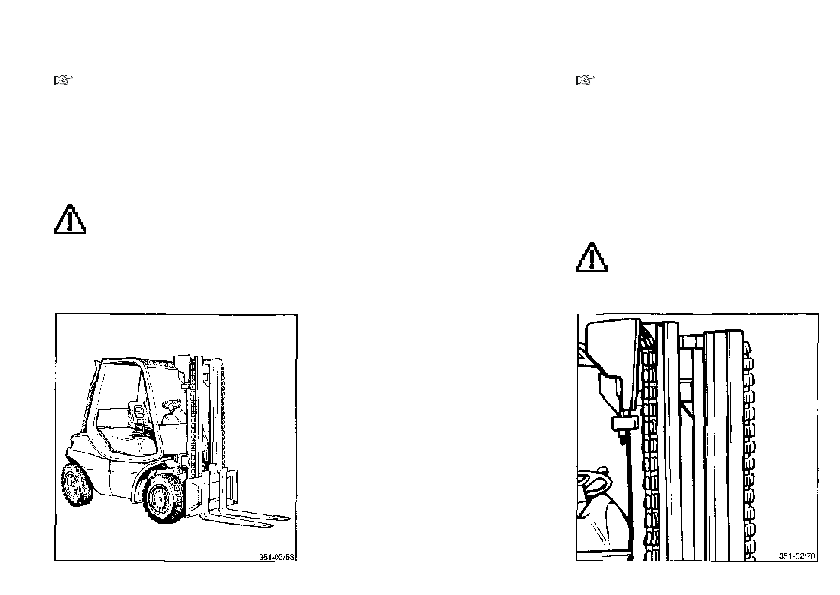
Inspection and maintenance as required Maintenance
Clean the lift truck
NOTE
The necessity of cleaning depends on the use of the truck.
If used with aggressive media such as salt water, fertilizer,
chemicals, cement, etc., clean the truck thoroughly after
every application.
Hot steam or intensive degreasing solution should be used
with the utmost care! If not, the grease in the lubricated-forlife bearings will dissolve and leak out. As regreasing is not
possible, damage to the bearings will result.
Do not wash the truck when the engine is hot.
ATTENTION
When cleaning with a water jet (high pressure or
steam jet cleaning device, etc.) do not directly
expose the electrical or electronic components
as well as the connectors to the jet. If this cannot be
avoided, cover them first.
Regularly remove inflammable debris especially on or in
the area of parts with a high temperature such as exhaust
pipes.
351 807 1301.0407
When cleaning with compressed air, remove sticking dirt
with a cold cleaner.
Clean the oil filler openings, surrounding areas and grease
nipples before lubrication.
Cleaning and spraying the mast chain
NOTE
The mast chain must be cleaned if the dust on the chain
prevents penetration of the lubricant.
- Place a container under the mast.
- Clean the chain with paraffin derivatives such as washing
petrol (observe manufacturer's notes on safety).
- When using a steam jet, clean without additives.
- After cleaning, blow dry the chain at once to remove any
water in the chain links and on the surface. Move the chain
several times during this procedure.
- Immediately spray Linde chain spray on the chain, while
also moving it.
ATTENTION
Lifting chains are safety components. The use of
cold cleaners, chemical cleaning agents and
caustic or acidic and chlorinated fluids can be a direct
cause of damage to the chain.
Page 51
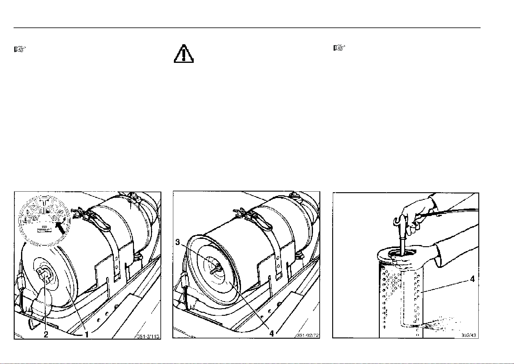
Inspection and maintenance as required Maintenance
Cleaning the air filter
NOTE
Cleaning the air filter element is necessary only when the
air filter restriction indicator in the composite instrument
illuminates.
A restricted air filter results in loss of power and increased
engine wear. Therefore careful and regular servicing of
the air filter is essential to engine life and performance.
Carry out all services on the air intake system with the
engine stationary. Do not start engine when the filter
element is removed.
- Open the engine cover.
- Screw off the wing nut (2) and remove the air filter cover (1).
- Screw out the nut (3) and pull out the air filter element (4).
Cleaning with compressed air
ATTENTION
Do not clean the filter casing with compressed
air, wipe it with a clean cloth.
- To clean the filter element (4), blow dry compressed air
at max. 5 bar pressure from the inside to the outside until
the filter is free of dust.
- Before installing the cleaned air filter element, examine
it for damage eg at paper of filter element, rubber seals,
for dents or bulges on the metal frame
- Using an inspection lamp, examine the paper part of the
filter element for cracks and holes.
- Renew a damaged filter element.
NOTE
Mark every servicing on the filter element.
Discard the filter element if it has been cleaned 5 times, if
damaged, after 1000 service hours, or at least every 12
months.
- Re-install the filter element into the filter casing. Make
sure that the filter element is not damaged and that the
seal on the filter casing fits properly.
- Note the arrow symbol on the dust bowl indicating the top.
- Refit the air filter cover.
351 807 1301.0407
Page 52
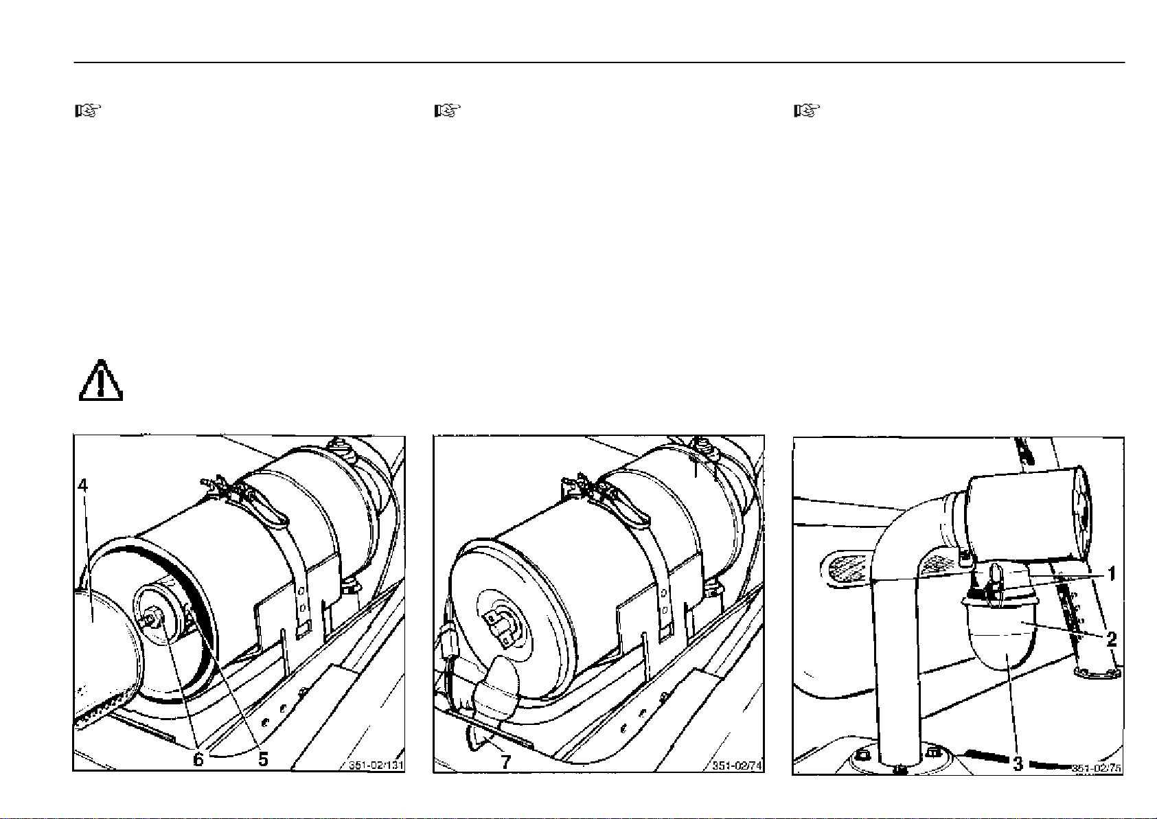
Inspection and maintenance as required Maintenance
Renewing the safety element
NOTE
The safety element is only installed if a prefilter* is fitted to
the air filter.
Changing the safety element (5) is required:
- After cleaning the main element (4) five times.
- The number of services (renewal or cleaning) must be
recorded on the appropriate marks of the safety element.
- After 2 years of operation maximum.
If, after servicing the main element, the air filter warning
light responds again.
- When the main element is damaged:
- Remove the air filter cover and the main element.
- Unscrew the hexagonal nut (6) and pull out the
safety element (5).
- Install the new safety element and fasten with the
hexagonal nut (6), filter element (4) and refit the air
filter cover.
ATTENTION
Safety elements may neither be cleaned nor reused.
* Option
351 807 1301.0407
*
Checking the dust discharge valve
NOTE
The dust discharge valve (7) is largely maintenance-free.
- If required, squeeze the valve and remove the remaining
dust.
Replace the valve if damaged.
- Close the engine cover.
Cleaning the prefilter
NOTE
The dust bowl (3) should never be more than half filled (2)
with dust. Daily servicing may be necessary under excessive dust conditions.
- Loosen clips (1) and remove dust bowl (3). Clean the dust
bowl.
- Refit the dust bowl and secure with the clips.
* Option
*
Page 53
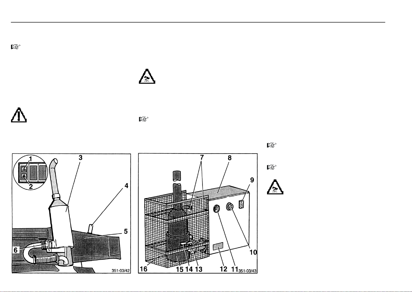
Inspection and maintenance as required Maintenance
* Option
Regenerate the soot particulate filter* (variant I)
NOTE
The soot particulate filter must be regenerated at least
every 6 hours. The warning lamp (1) (yellow) illuminates
after 5 hours as visual indicator. A maximum of 1 hour
remains until regeneration is required. The on-going work
should be completed and a filter change scheduled. After
the 6 hours are up, the second warning light (2) (red)
illuminates, accompanied by an acoustic signal. The truck
must now be shut down at once and the filter either
regenerated or renewed, otherwise the filter will be destroyed.
ATTENTION
When the power fails (e.g. battery disconnected),
the installed hour meter is automatically reset to
zero. For safety reasons, the soot particulate filter should
be regenerated at once. Otherwise the exhaustion time
and filter capacity will be exceeded.
Remove the soot particulate filter
- Drive to the regeneration station.
- Stop the engine.
- Open the clip (4) and swing the guard (5) away.
CAUTION
Risk of burning! Use gloves.
- Remove the quick-disconnect coupling (6) by turning it
anti-clockwise.
- Remove the soot particle filter (3) without jolting it.
NOTE
When the filter is removed, the built-in hour meter is
automatically reset to zero by a limit switch.
Clean the soot particulate filter
- Remove the guard (16) at the regeneration station.
- Connect the soot particulate filter stress-free to the regenerator (8) with the quick-disconnect coupling (13).
- Close the insulation (15) and secure the clip (14).
- Hook the guard (16) into the pin (7).
- Turn the EMERGENCY OFF switch (10) clockwise until it
disengages and pops up.
- Start the regenerator by depressing the pushbutton (9).
When starting the regenerator, check its load condition at the
pressure gauge (11):
Gauge indication:
green = filter new or regenerated
black = regular filter load
red = filter overload
Contact your authorised distributor.
NOTE
Regeneration time.........................................approx. 40 min.
Cooling time ....................................................approx. 30 min.
NOTE
The air heater and fan motor stop automatically.
351 807 1301.0407
CAUTION
Risk of burning! Regenerate the filter only with the
guard in place. The filter surface temperature
can reach 700 oC. Observe the notice label (12).
Depress the EMERGENCY OFF switch (10) in case of danger.
- Take the soot particulate filter out of the regenerator.
- Re-install the soot particulate filter in the truck.
Page 54
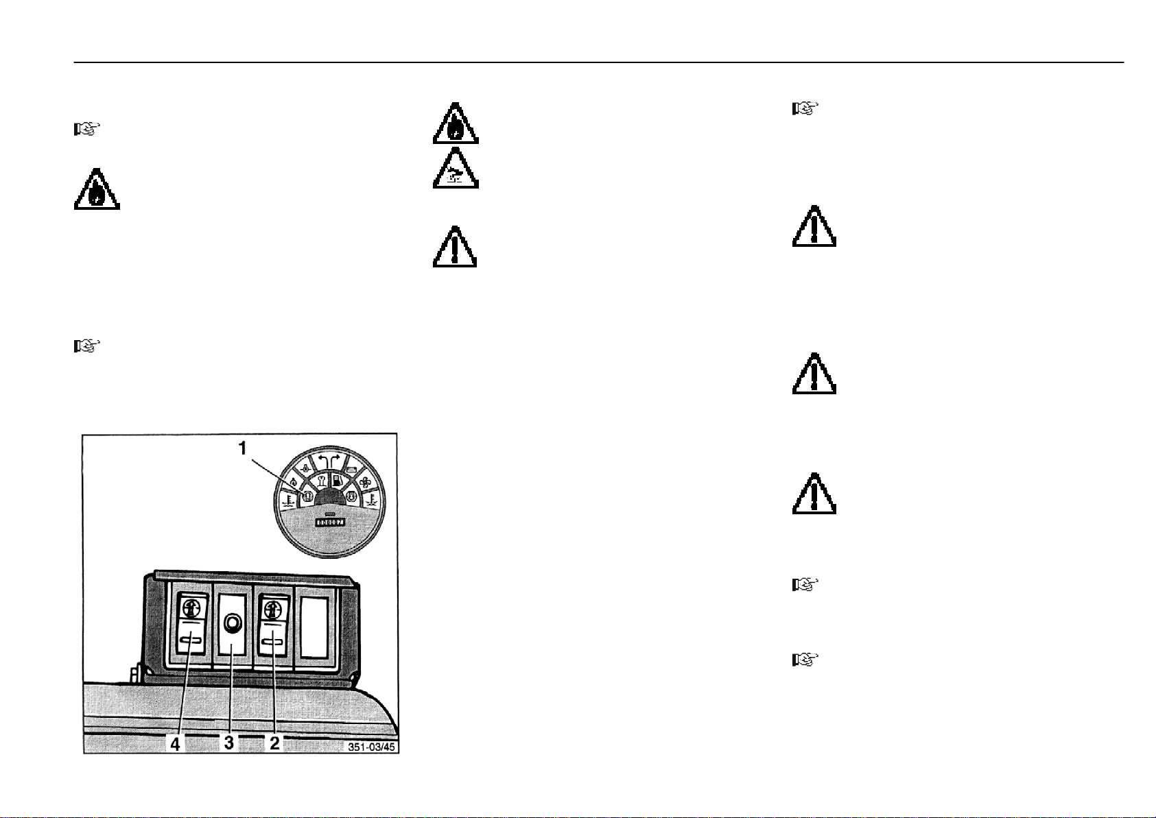
* Option
Inspection and maintenance as required Maintenance
Regenerate the soot particulate filter* (variant II)
NOTE
The switches can either be mounted in the console or in a
separate box on the console.
WARNING
Do not fuel the truck during filter regeneration.
NOTE
The soot particulate filter must be regenerated at least
every 8.5 engine service hours. The yellow soot warning
lamp (1) lights as visual indicator after 7.5 hours. The filter
must be regenerated within the next 30 min. If this period
is exceeded, the buzzer will sound (intermittently for half
an hour, then continuously). In this case shut the engine off
as soon as possible and regenerate the filter.
NOTE
A regeneration can also be started before the maximum
exhaustion time is reached.
351 807 1301.0407
CAUTION
Perform regeneration only in the open with the
engine at operating temperature and not in the
vicinity of inflammable goods.
The exhaust gases must not be conducted into an
air evacuation system for fire safety reasons.
The exhaust gases must not be conducted into an air
evacuation system for fire safety reasons.
ATTENTION
The filter can be regenerated only when the engine is switched off (ignition off).
- Thoroughly clean the exhaust duct.
- If over 30 min have elapsed after stopping the engine,
briefly turn the preheating switch to position I and then
back to the zero position (turn ignition on briefly and off
again). The soot filter control remains active for another
30 minutes. During this period regeneration can be
started.
- Unlock switch (3) by depressing the lock (4), and press
the switch for approx. 6 seconds until the built-in yellow
switch light (ON indicator) illuminates. The lamp will stay
on until the end of the regeneration cycle, which lasts
approx. 23 minutes.
Regeneration proceeds automatically, i. e. preheating
approx. 60 seconds, burning approx. 10 minutes and afterventilation approx. 5 minutes. After a successful regeneration, the switch lamp (ON indicator) will extinguish and the
truck can be operated again.
area, or the regeneration must be stopped for safety
reasons,
- Unlock and operate EMERGENCY-OFF- switch (2).
The regeneration procedure will be stopped immediately
and the truck can be started. (Only operate in an emergency, as the system can be damaged.)
If a soot alarm was signalled before the interrupted regeneration procedure, the alarm will continue. In this case a
complete regeneration must be carried out.
buzzer buzzes. Start regeneration again. If a fault occurs
again, shut down the truck and contact your authorised
dealer.
NOTE
ATTENTION
The engine cannot be started during regeneration. If the truck must be removed from a security
ATTENTION
The soot particulate filter is not regenerated if the
regeneration procedure is interrupted!
ATTENTION
If a fault occurs during regeneration the red warning lamp in the emergency OFF (2) blinks and a
NOTE
To shut off the buzzer in the emergency OFF (2), unlock and
operate. If the buzzer continues to buzz, please contact
your authorised dealer.
NOTE
During operation the regeneration system glow plug is
cleaned every 1.75 hours by means of intermediate glow-
ing.
Page 55
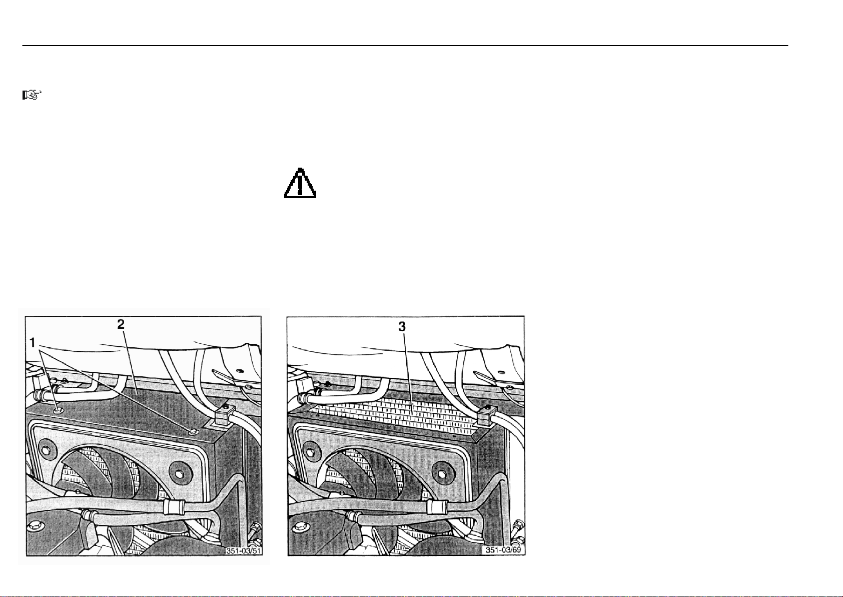
Inspection and maintenance as required Maintenance
Clean and check the radiator and hydraulic
oil cooler for leaks
NOTE
Only clean the radiator and hydraulic oil cooler when the
engine is stopped and cool.
- Open the engine cover.
- Remove screws (1) and take off the radiator cover (2).
Cleaning with compressed air
- Clean the radiator (3) with compressed air from the
engine side.
- Flush any loosened dirt off with a water jet.
Cleaning with a cold cleaner
- Clean the radiator (3) with a commercial cold cleaner and
allow it to soak in for approx. 10 minutes.
- Clean the radiator with a strong water jet from the engine
side.
ATTENTION
Protect the alternator against the direct water jet.
- Let the engine run warm to evaporate any residual water
and prevent rust formation.
- Check connectors, coolant hoses and pipes at the radiator and hydraulic oil cooler for leaks.
- Renew porous hoses, retighten loose clamps, if necessary.
- Refit the cover (2).
A
351 807 1301.0407
1
3
Page 56
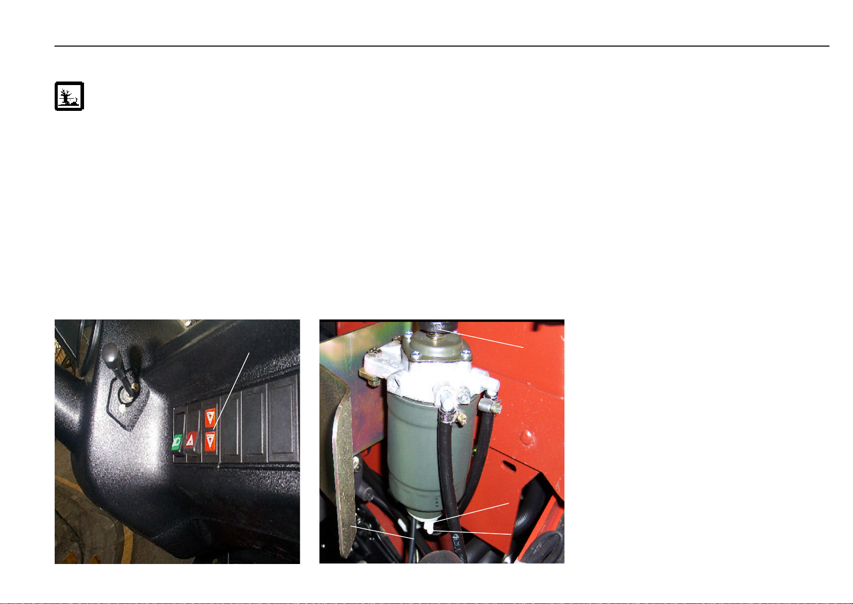
Drain the fuel system water preseparator
ATTENTION
Drain the fule system water is necessary only
when water restriction indicat(A) illuminates.
Follow the precautions for handling fuels and lubri-
cants.
- Press the drain pump (1) by hand, and drain off any water
collected inside.
- Retighten the drain plug.
- Open the engine cover.
- Make a visual inspection for any water in the preseparator
and drain it, if necessary.
- Loosen the drain plug (2) and turn out about 3-5 turn.
- Connecting a drain hose (4) to drain connector (3) ,
and another of drain hose (4) connecting to a suitable
container .
351 807 1301.0407
A
- Close the engine cover.
5
1
2
4
3
Page 57
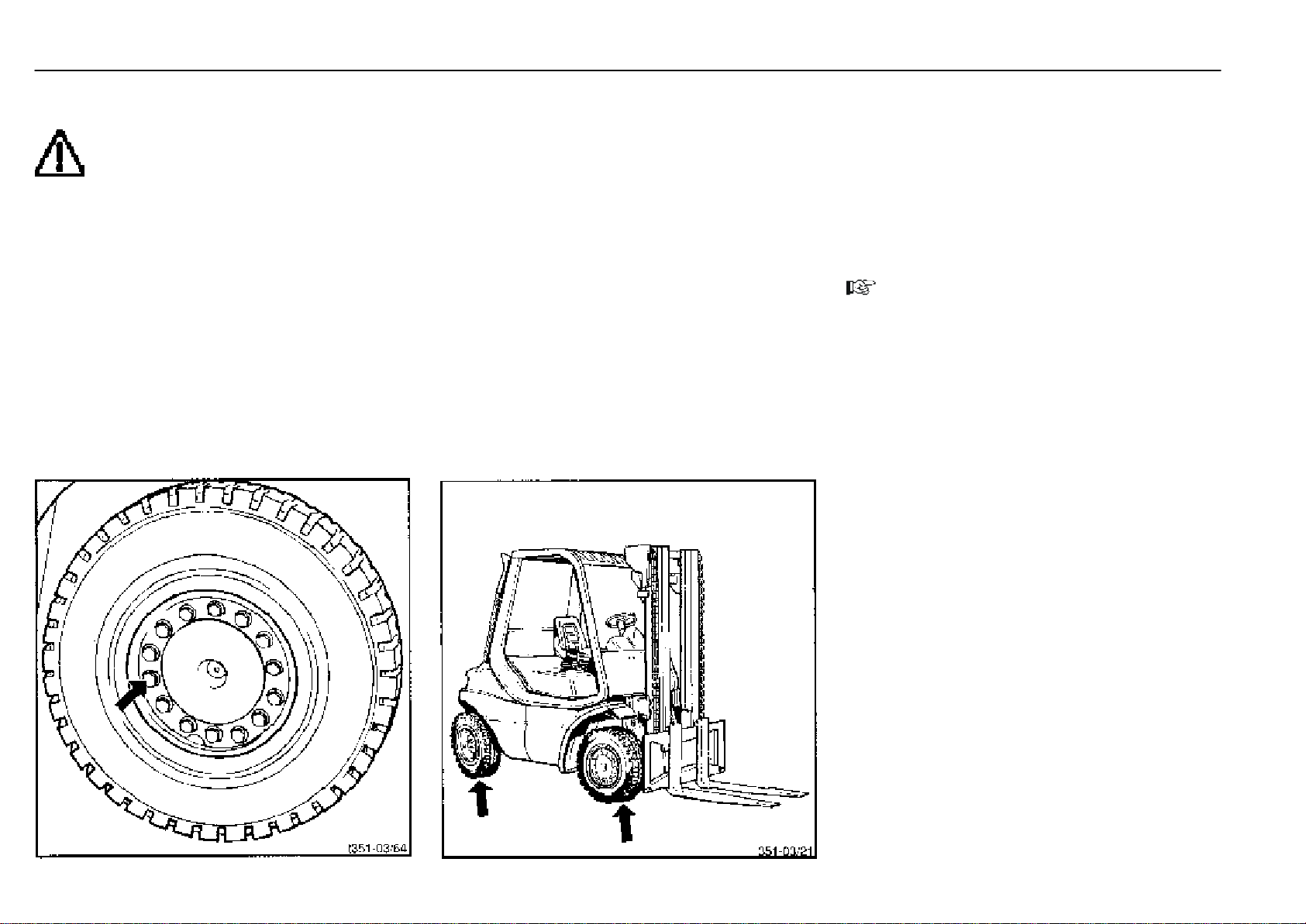
Inspection and maintenance as required Maintenance
Tighten the wheel fasteners
CAUTION
At least every 100 hours.
- Tighten opposite wheel fasteners to a torque of:
front:............................................................................195 Nm
rear: ............................................................................400 Nm
Check the tyres for damage and foreign
objects
- Secure the truck against rolling (apply parking brake).
- Chock a wheel that is not to be jacked up.
- Raise the truck with a jack until the wheels are clear of the
ground.
- Secure the truck with squared timbers.
- Check the wheels for ease of rotation and remove anything hindering their free movement.
- Replace worn or damaged tyres.
Lubricate the steer axle, mast and tilt cylinder bearings
If used in clean and dry areas, truck servicing every 500
service hours is sufficient as a rule. For mixed use inside and
outside, it is recommended that the lubrication interval be
halved.
In an environment with dust, dirt, water and possibly de-icing
salt or chemicals, weekly lubrication will extend the service
life of the bearings substantially.
NOTE
Preferably lubricate the bearings with less grease more
often than a lot of grease less frequently.
351 807 1301.0407
1
2
4
3
Page 58
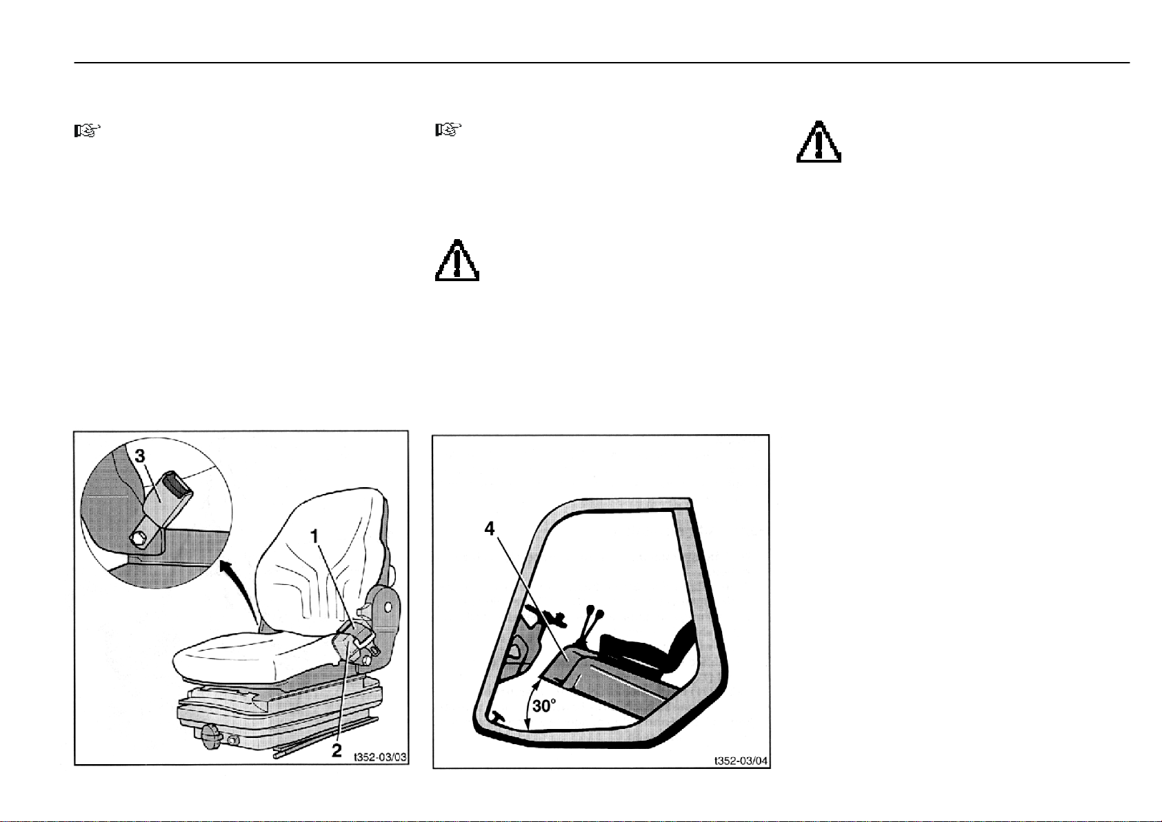
Inspection and maintenance as required Maintenance
Check seat belt for condition and proper
operation
NOTE
For safety reasons the condition and proper operation of
the retention system should be inspected regularly (monthly). Under extreme operating conditions this check is
required daily before taking the truck into operation.
- Pull the belt (1) out fully and inspect for fraying.
- Check the lock (3) for correct operation and the retractor
for proper return of the belt.
- Check covers for damage.
- Check the automatic lock.
- Park the truck on level ground.
- Pull out the belt with a jerk.
The automatic lock should prevent the belt from
unrolling from the retractor (2).
- Slide the seat fully forward.
351 807 1301.0407
NOTE
When opening the bonnet, watch out for a possibly installed rear windscreen*.
- Open the bonnet (4) about 30o.
The automatic lock should prevent the belt from
unrolling from the retractor (2).
CAUTION
Do not operate the truck with a faulty seat belt.
Have a defective seat belt replaced immediately
by your authorised dealer.
* Option
CAUTION
To prevent back injury, the weight setting should
be set to the individual weight of the driver.
To prevent injuries, do not store any objects in the tilting
range of the seat.
To prevent accidents, check that all adjustments are
properly engaged before operating the truck.
Do not operate the seat adjusting devices while operating
the truck.
Seat belts must be applied before operation of the truck.
After an accident, the seat belt must be renewed. In the
case of seat belts attached to the operator seat, the seat
and mounting of the seat must also be inspected by
qualified personnel.
Nuts and bolts should be checked regularly for tightness.
A wobbling of the seat can indicate loose bolts or other
faults. If malfunctions in the operation of the seat are
detected (e.g. seat cushioning), contact your authorised
dealer immediately to eliminate the cause. In case of nonobservance, you put your health in danger and there is a
higher risk of accidents.
Page 59
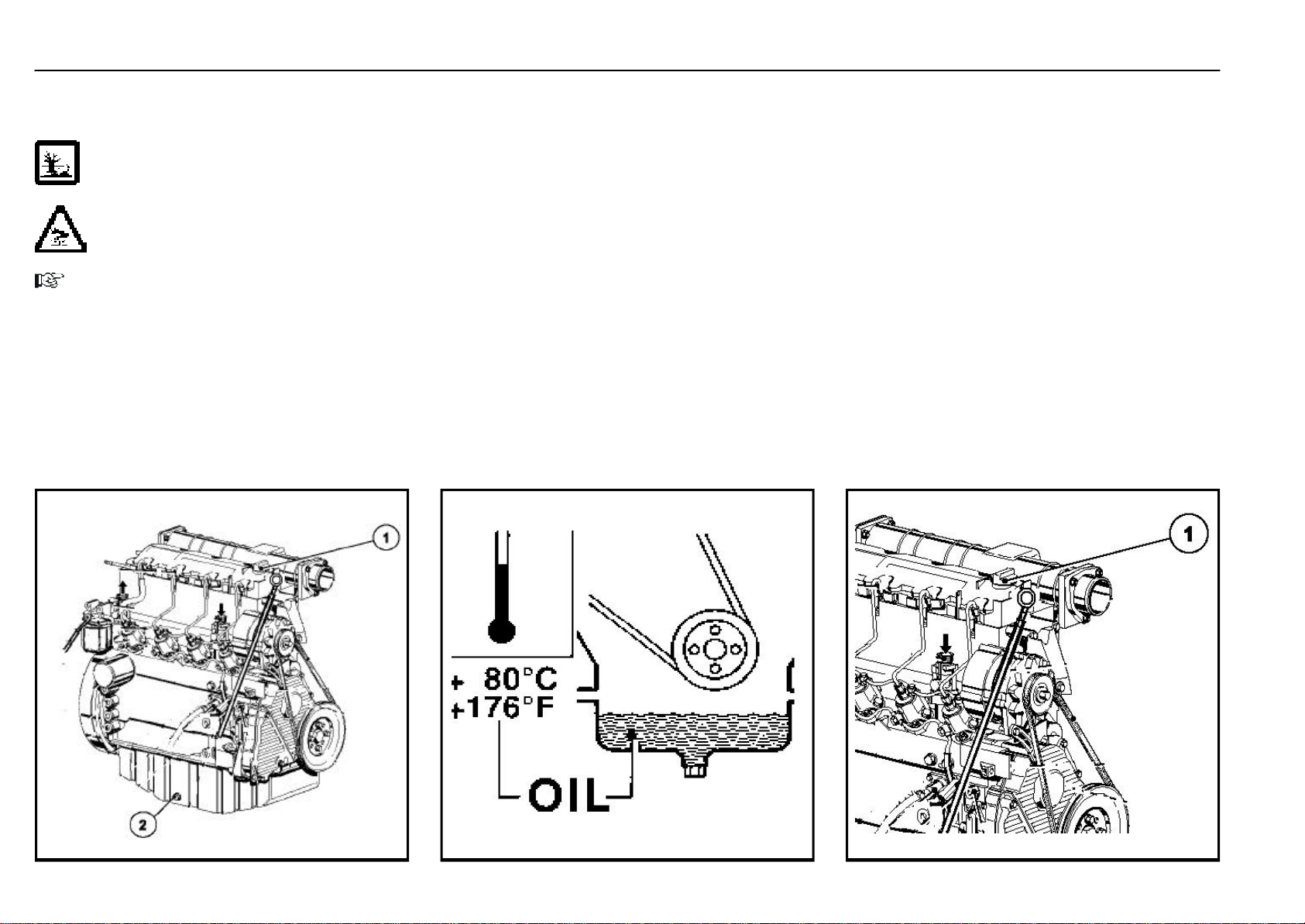
500-hour inspection and maintenance Maintenance
Renew the engine oil (every 12 months minimum)
Drain the engine oil
ATTENTION
Follow the precautions for handling fuels and
lubricants.
CAUTION
Risk of scalding when draining hot engine oil.
NOTE
Change oil only when the engine is at operating temperature.
- Drive truck over a repair pit.
- Place a suitable container under the frame.
- Open the engine cover.
- Start the engine and bring it up to operating temperature
(approx.80oC).
- Stop the engine.
- Remove the cap (1) from the filler opening to vent the
engine crankcase and allow the engine oil to drain more
easily.
- Push up the rubber mat over the opening in the floor.
- Remove the engine oil drain plug (2) on the engine sump
from below.
- Allow the oil to drain completely into the container.
- After all oil has been drained from the engine.
refit the drain plug .
Torque to ............................................................................ 55Nm
- Lower the rubber mat back in place.
Top up engine oil
- Remove the cap (1) on the filler opening.
- Fill new engine oil through the filler opening.
Filling capacity
- with filter renewal ................................................... max. 9 L
- After refilling, check the engine oil level with the dipstick
and add oil to the maximum mark, if necessary.
- Install and tighten the engine oil cap (1).
NOTE
During the trial run after the oil change and filter renewal,
observe the oil pressure warning light and watch for
leakage at the oil drain plug and oil filter.
An accurate check of the oil level, particularly after renewing the oil filter, requires stopping the engine again and
rechecking the oil level after about one minute.
351 807 1301.0407
Page 60
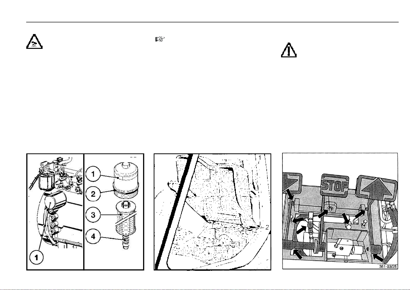
500-hour inspection and maintenance Maintenance
Renew the engine oil filter cartridge
CAUTION
Risk of scalding when draining hot engine oil.
- Stop the engine.
- Loosen the engine oil filter cover (1) using a filter spanner
and remove by hand.
- Carefully loosen paper filter cartridge (3) upwards from
guide (4).
- Catch any escaping oil and replace paper filter cartridge
(3).
- Clean any dirt from sealing surface of filter carrier and
lube oil filter cover (1) and from guide (4).
- Replace and lightly oil rubber gasket (2).
- Carefully insert new paper filter cartridge (3) into guide
(4).
- Screw in the oil filter cover (1) by hand until the seal is
seated, then tighten an additional 3/4 of a turn using the
filter spanner.
351 807 1301.0407
Clean the radiator and hydraulic oil cooler
NOTE
Only clean the radiator and hydraulic oil cooler when the
engine is stopped and cool.
- Remove the radiator cover (1).
Cleaning with compressed air
- Clean the radiator with compressed air from the engine
side.
- Flush any loosened dirt off with a water jet.
Cleaning with a cold cleaner
- Clean with a commercial cold cleaner and allow to soak
in for approx. 10 minutes.
- Clean the radiator with a strong water jet from the engine
side.
ATTENTION
Protect the alternator against the direct water jet.
- Let the engine run warm to evaporate any residual water
and prevent rust formation.
Check and oil the pedals, travel control and
engine control linkages
ATTENTION
The following work must be carried out by qualified service staff. Please contact your authorised
dealer.
- Check pedals for ease of operation.
- Check the pin and pivot circlips for tight seating.
- If necessary, slightly oil lever pivots and clevises.
Page 61
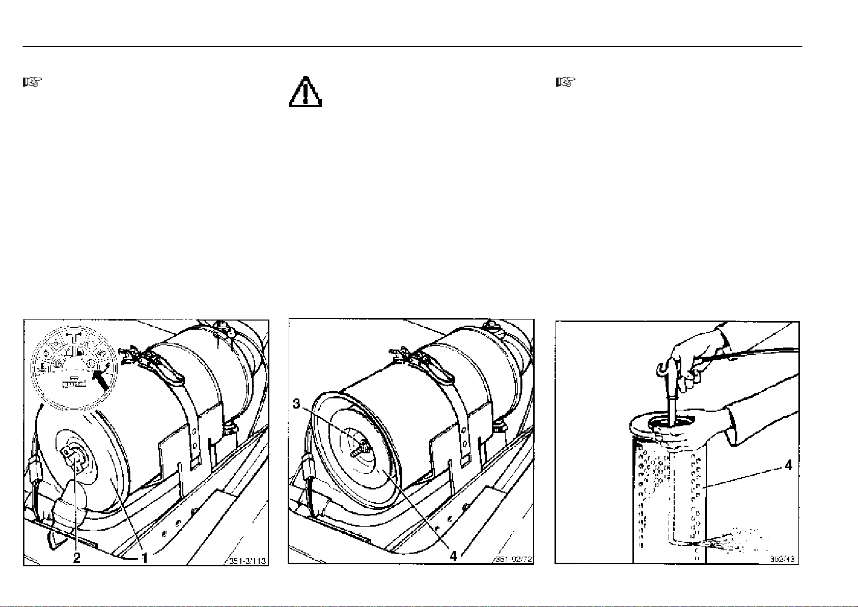
500-hour inspection and maintenance Maintenance
Cleaning the air filter
NOTE
A restricted air filter results in loss of power and increased
engine wear. Therefore careful and regular servicing of
the air filter is essential to engine life and performance.
Carry out all services on the air intake system with the
engine stationary. Do not start engine when the filter
element is removed.
- Open the engine cover.
- Screw off the wing nut (2) and remove the air filter cover (1).
- Screw out the nut (3) and pull out the air filter element (4).
Cleaning with compressed air
ATTENTION
Do not clean the filter casing with compressed
air, wipe it with a clean cloth.
- To clean the filter element (4), blow dry compressed air
at max. 5 bar pressure from the inside to the outside until
the filter is free of dust.
- Before installing the cleaned air filter element, examine
it for damage eg at paper of filter element, rubber seals,
for dents or bulges on the metal frame
- Using an inspection lamp, examine the paper part of the
filter element for cracks and holes.
- Renew a damaged filter element.
NOTE
Mark every servicing on the filter element.
Discard the filter element if it has been cleaned 5 times, if
damaged, after 1000 service hours, or at least every 12
months.
- Re-install the filter element into the filter casing. Make
sure that the filter element is not damaged and that the
seal on the filter casing fits properly.
- Note the arrow symbol on the dust bowl indicating the top.
- Refit the air filter cover.
351 807 1301.0407
Page 62
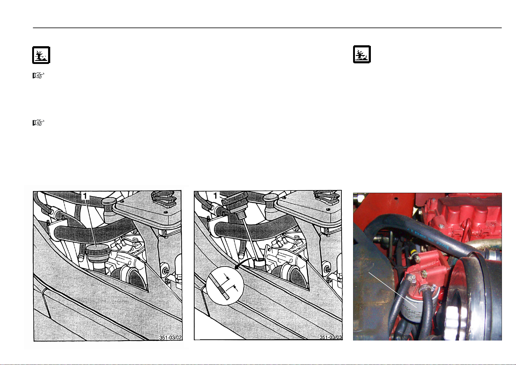
500-hour inspection and maintenance Maintenance
Check the hydraulic system oil level
ATTENTION
Follow the precautions for handling fuels and lubricants.
NOTE
For the oil level check, the fork carriage of the mast must
be lowered completely.
- Screw out the breather filter (1) with oil dipstick on the right
side of the truck.
NOTE
The tank is slightly pressurised. Some air will escape.
351 807 1301.0407
- Wipe the oil dipstick with a clean cloth.
- Screw in the breather filter with oil dipstick fully and screw
out again.
- Oil level should be between both markings on the dipstick.
- If necessary, add hydraulic oil up to the upper mark.
Capacity between max. and min. marks ........ approx. 2.0 L
Renew the fuel filter (every 12 months minimum)
ATTENTION
Follow the precautions for handling fuels and lubricants. The fuel system must be bled.
- Place a suitable container beneath the fuel filter.
- Clean the exterior of the filter.
- Remove the fuel filter (1) using a filter wrench.When
removing the filter , hold the bottom of the fule filter with
a piece of rag to prevent the fuel oil from dropping. If you
spill fuel, wipe such spillage carefully.
- Clean the sealing surface of the filter head and bowl.
- Coat the rubber gasket of a new filter with fuel.
- install the new fuel filter manually turing it clockwise until
it comes into contact with the mountingsurface, and
tighten it further to 1/2 turn using a filter wrench.
1
Page 63
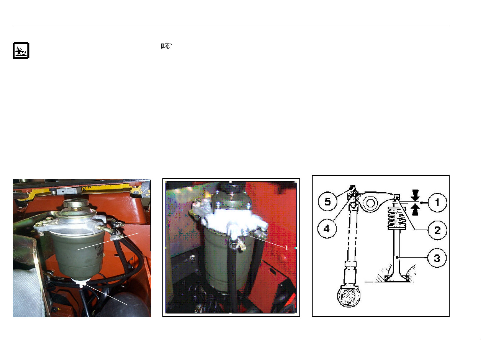
500-hour inspection and maintenance Maintenance
234111132
414
Renew the fuel system water pre-separator
ATTENTION
Follow the precautions for handling fuels and
lubricants.
- Open the engine cover.
- Place a suitable container beneath the water separator..
- Clean the exterior of the water separator..
- Remove the fuel filter (1) using a filter wrench.When
removing the separator, hold the bottom of the fule filter
with a piece of rag to prevent the fuel oil from dropping. If
you spill fuel, wipe such spillage carefully.
- Clean the sealing surface of the separator head and
bowl.
- Coat the rubber gasket of a new filter with fuel.
- Remove the drain plug (2) from separator and fix to new
separator.
- install the new separator with drain plug (2) manually
turing it clockwise until it comes into contact with the
mounting surface, and tighten it further to 1/2 turn using
a filter wrench.
- Close the engine cover.
Bleed the fuel system
NOTE
This is required if the truck has been driven until the fuel
tank is empty, the fuel pump was cleaned, or the fuel filter
was changed.
- Loosen the air bleeding bolt (1) on the oil/water separator
by turning 2 - 3 times to the counter-clockwise.
- Turn the starter switch to the ON position and hold it in the
position for 10-15 seconds to operate the fuel feeding
pump.
- When the fuel coming out is clear and not mixed with any
bubbles, tighten the air bleeding bolt (1) .
Check and adjust valve clearance
Proper adjustment is necessary to maintain the correct
timing for opening and closing the valves. Improper adjustment will cause the engine to run noisily, resulting in poor
engine performance and engine damage.
NOTE
The adjustment of the valve clearance requires special
tools and skills. Please contact your authorised dealer.
- Stop the engine.
- Befor adjusting valve clearance, allow engine to cool
down for at least 30 minutes. Oil temperature shold be
below 80oC.
- Remove the cylinder head cover.
351 807 1301.0407
- Position crankshaft.
1
2
Page 64
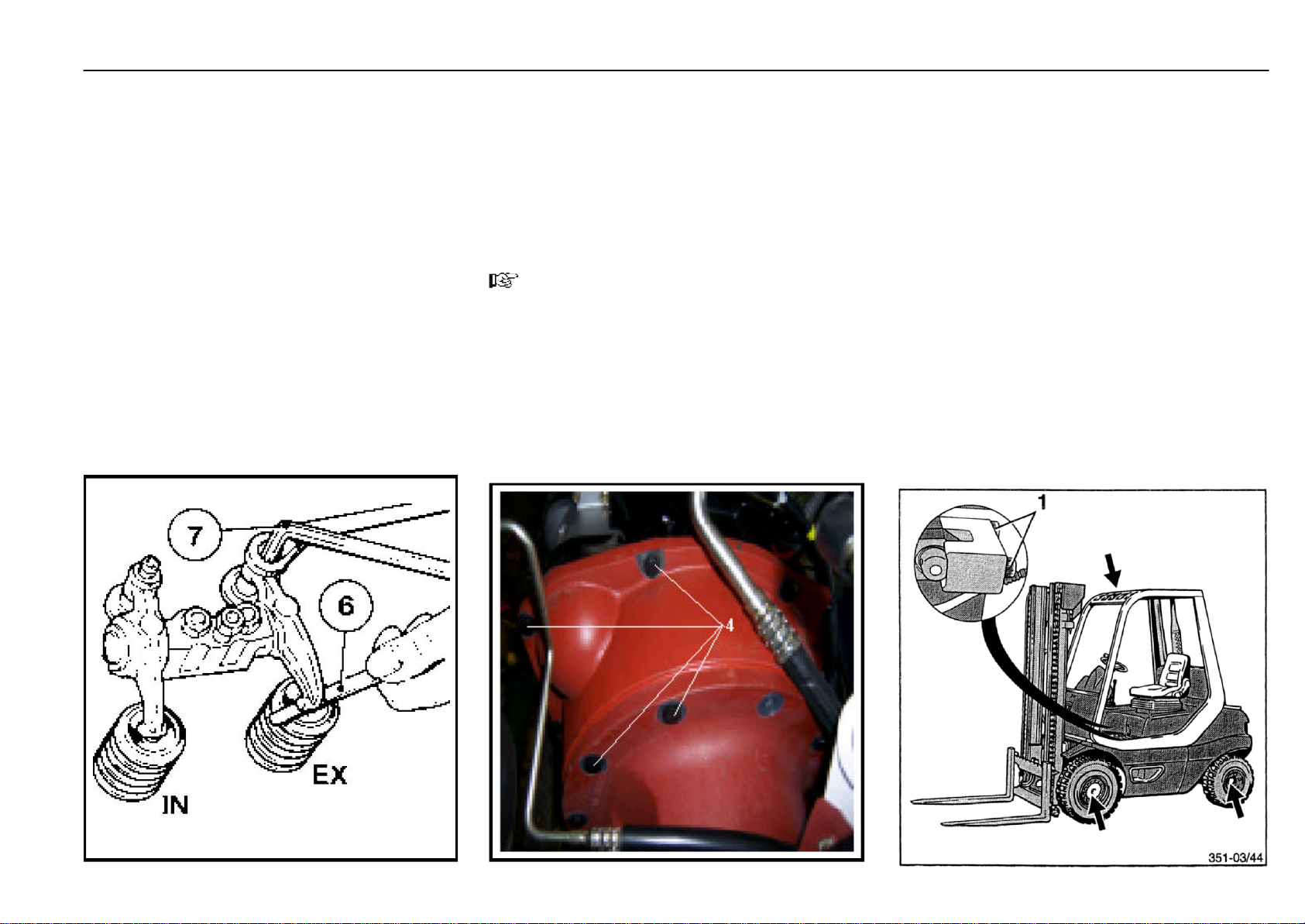
500-hour inspection and maintenance Maintenance
- Check valve clearance( 1) between roker arm/tappet
contactface( 2 )and valve stem (3 )with feeler gauge (there
should be only slight resistance when feeler blade is
inserted).
- Permissble valve clearace with cold engine:
Inlet 0.3
exhaust 0.5
1
...................................................................................................................................................
- Adjust valve clearance if necessary:
Release locknut (4). Use Allan Key (7) to turn setscrew (5)
so that correct clearance to attained after locknut (4) has
been tightened.
- Chek and adjust valve clearance on all cylinders.
- Reinstall cylinder head cover, with new gasket if necessary.
351 807 1301.0407
+0.1
+0.1
mm
mm
Check the mounting of the compact axle at
the engine
- Remove the floor plate.
- Tighten any loose bolts.
- Hexagonal bolts (4)
Torque .................................................................................64 Nm
NOTE
The intermediate housing is mounted on the engine with
M12bolts.
Torque .................................................................................32 Nm
Check the mounting of the engine, counterweight, overhead guard, steering axle, tilt
cylinder and wheel drives for tightness
- Check the mounting of the engine, steering axle, drive
axle, counterweight and overhead guard for tightness of
fasteners and for wear.
- Tighten any loose nuts and bolts.
- Replace damaged parts.
- If necessary, touch up the paint coat.
- Tighten the tilt cylinder mounting bolts (1) at the frame to
a torque of 275 Nm.
Page 65
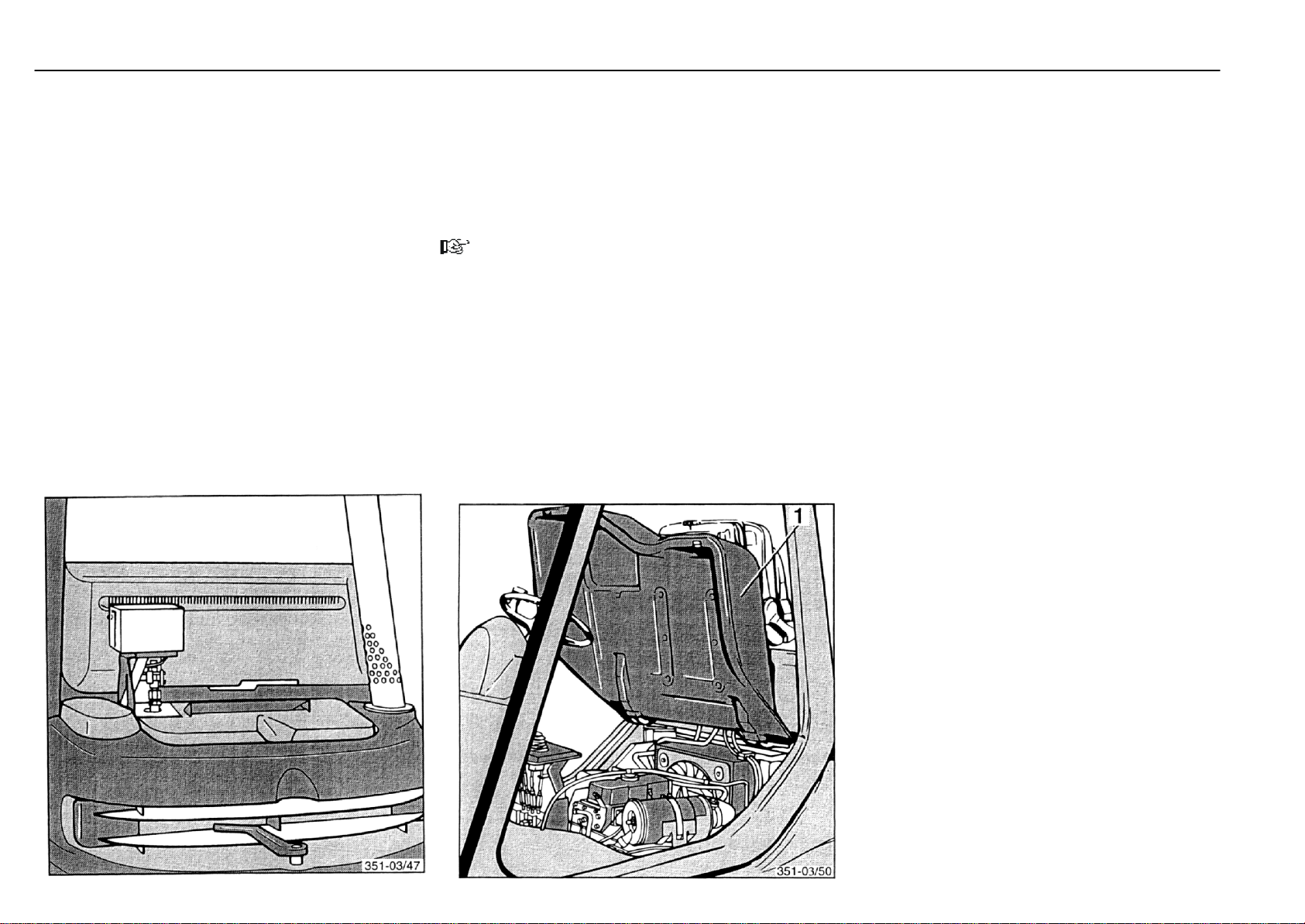
500-hour inspection and maintenance Maintenance
Checking the soot particulate filter system
- Check the electric contacts for tightness, corrosion and
damage.
- Check the combustion air hose for damage, leaks and
security.
- Check fuel-conducting lines and parts for damage, leaks
and security.
- Check the system for correct operation (soot warning,
acoustic alarm, regeneration, diagnostic lamp).
- Check the burner mounting for leaks, security and deformation.
- Clean the corrugated hose and elbow (fan to burner).
Please contact your authorized distributor for the servicing.
*
Check electric cables, cable connectors and
connections for condition and tightness
- Check cable connections for tightness and oxidation.
- Check earth lead for tightness.
- Check electric wiring for chafe marks and tightness.
NOTE
Oxidized terminals and cracked cables result in loss of
voltage, thus leading to starting difficulties.
- Remove oxidation remains and replace any cracked
cables.
351 807 1301.0407
* Option
Page 66
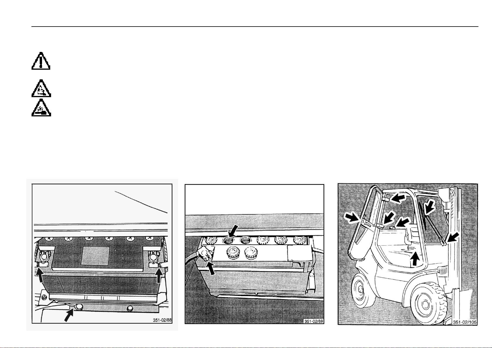
500-hour inspection and maintenance Maintenance
Battery: Check condition, electrolyte level
and specific gravity
ATTENTION
Even a so-called maintenance-free battery must
be checked for proper condition, electrolyte level
and specific gravity.
ATTENTION
Battery electrolyte is very caustic. Avoid any
contact with battery electrolyte. If clothing, skin
or eyes nevertheless come in contact with electrolyte, flush the areas respective immediately
with water. If electrolyte comes into contact with
the eyes, seek medical aid immediately! Neutralise spilled
electrolyte at once.
- Pull the battery compartment cover out of the lock at the
bottom and remove upward.
- Check the battery to see whether tray is cracked, plates
are lifted or acid has drained.
351 807 1301.0407
- Unscrew caps and check the electrolyte level. On batteries with check tubes, the liquid should be at the bottom
of the tubes. On batteries without tubes, the liquid should
be 10 to 15 mm above the plates.
- If the electrolyte level is low, top up with distilled water only.
- Remove any oxidation at the battery poles and grease
with non-acidic grease.
- Retighten the pole clamps firmly.
- Check electrolyte specific gravity with a hydrometer. The
specific gravity should be between 1.24 and 1.28.
- Engage the battery compartment cover at the top and
push down into the lock at the bottom.
Check and oil other pivots and joints
Inspect and oil the pivots and mountings of:
- Seat guide, engine cover mounting pivot pin
- Windscreen wipers*
- Cab* door hinges and locks
- Check and grease the engine lock mounting and pretension.
* Option
Page 67

500-hour inspection and maintenance Maintenance
Clean and grease the steering axle
- Thoroughly clean the steering axle with water or cold
cleaner.
NOTE
Lubricate with grease.
- Lubricate the track rods and stub axles with lubricating
grease at the grease nipples (see arrows).
- Grease with a grease gun unti fresh grease is visible at
the bearings.
Grease the mast and tilt cylinder bearings
- Lubricate the nipples of the tilt cylinder bearings at the
frame with grease.
- Lubricate the nipple of the mast bearing on the left and
right side of the frame with lubricating grease.
- Lubricate the nipple of the tilt cylinder bearing on the left
and right side of the mast from the front lubricating grease
with lubricating grease.
- Lubricate with a grease gun until fresh grease emerges
at the bearings.
- Install the floor plate, close the bonnet.
351 807 1301.0407
Page 68
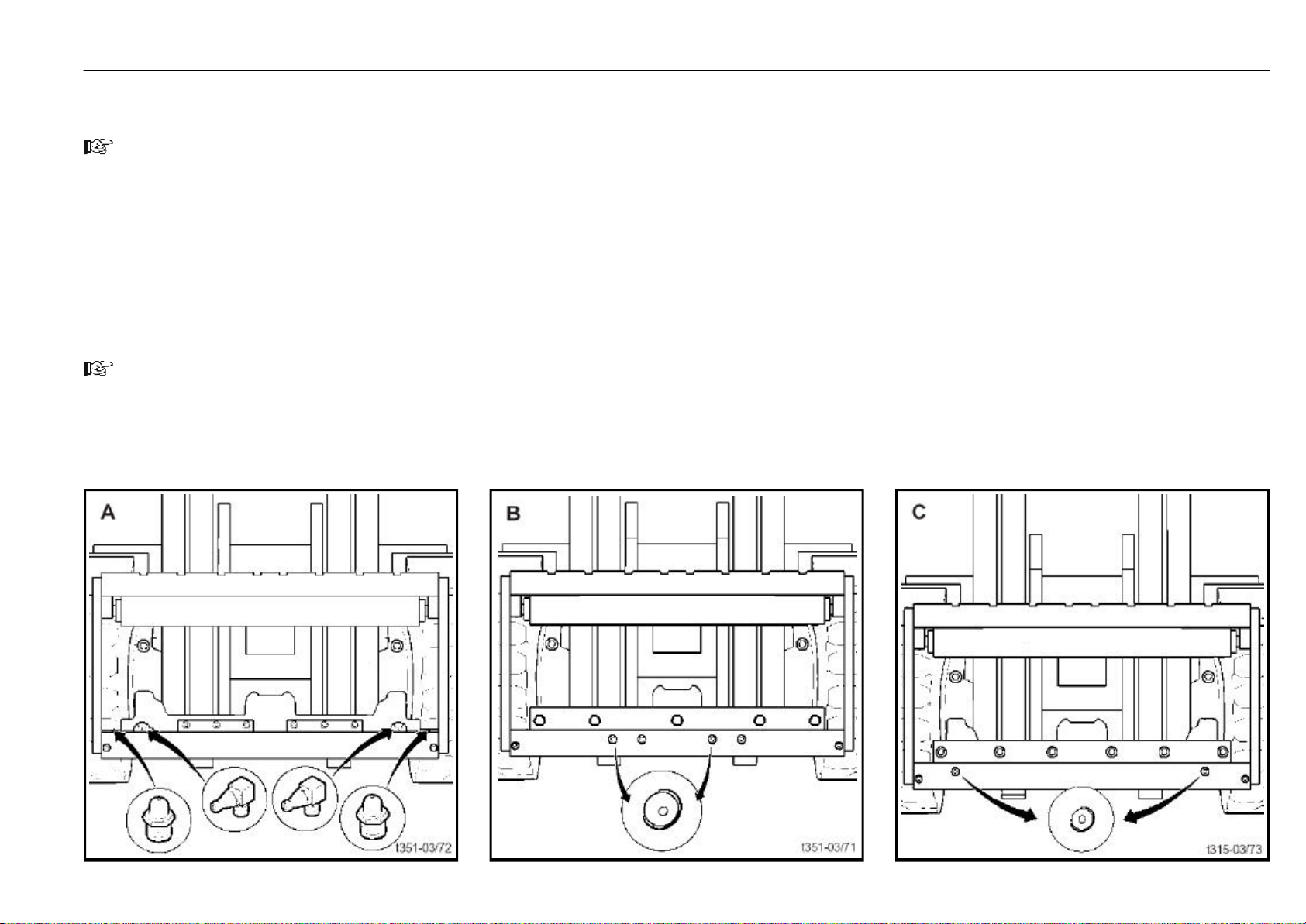
500-hour inspection and maintenance Maintenance
Clean and lubricate the sideshift*, check the
fasteners
NOTE
Use lubricating grease for lubrication.
- Clean the sideshift with a steam jet.
- Inspect the hydraulic lines for chafing, replace if required.
- Inspect the hydraulic lines and fasteners for security and
wear; tighten or renew as required.
- Lubricate the grease nipples depending on version A, B
or C at the fork carriage with lubricating grease until fresh
grease emerges at the side.
NOTE
The sideshift must be greased every time the truck is
washed.
* Option
351 807 1301.0407
Page 69
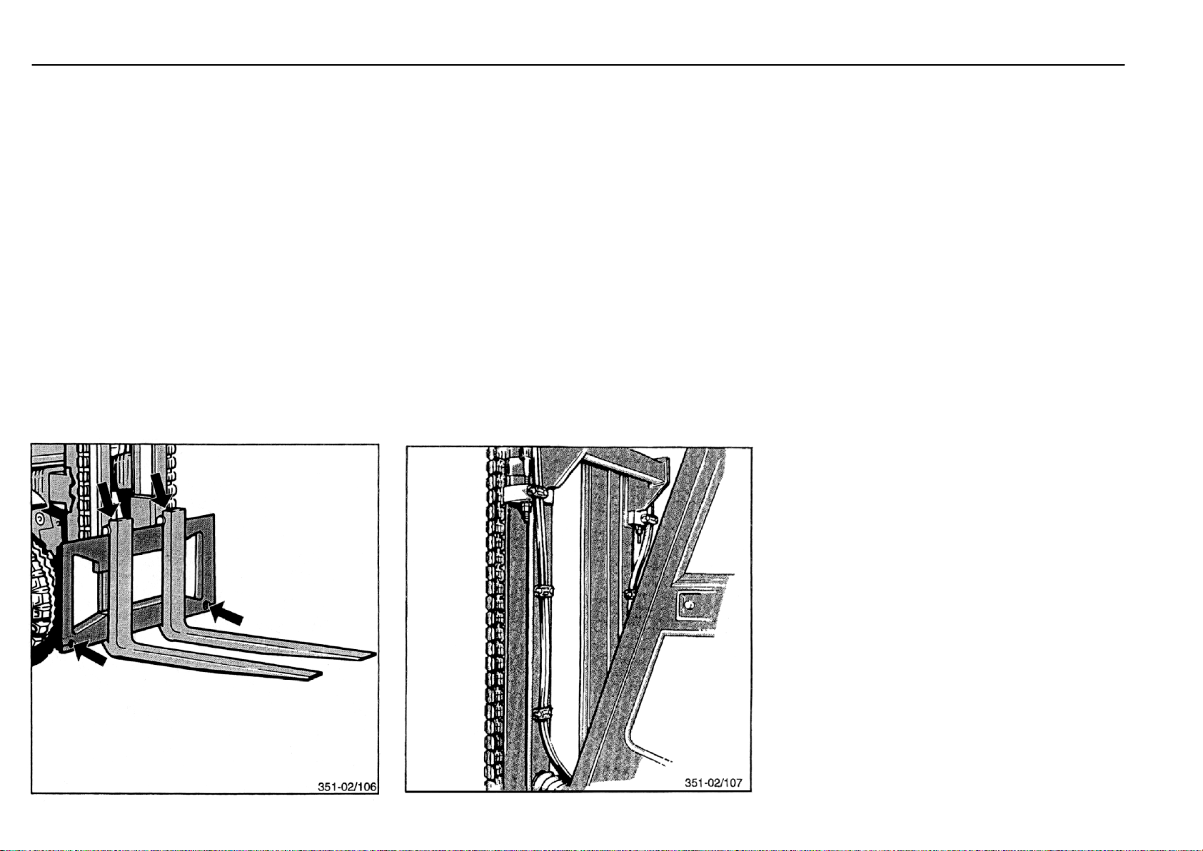
500-hour inspection and maintenance Maintenance
Check the forks and fork quick-releases
- Inspect the forks for visible distortion, wear and damage.
- Check the bolts fork stops and fork quick-releases for
correct seating and damage.
- Replace any damaged parts.
Check the pre-tension of double hoses if
attachments are fitted
- The pre-tension of double hoses should be 5 - 10 mm per
metre referred to initial length.
- Adjust the pre-tension to the specified tension by shifting
the hoses in the clamps.
351 807 1301.0407
Page 70
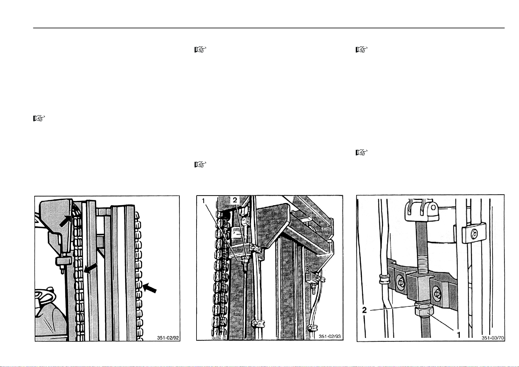
500-hour inspection and maintenance
Maintenance
Check the mast, lift chains and stops for
condition, mounting and operation
- Clean the mast channels and chains.
- Inspect the chains for condition and wear, especially in
the pulley area.
- Check the chain security at the chain anchor.
- Replace any damaged chains.
NOTE
Damaged or missing plastic links do not reduce the function and service life of the chain.
- Check mast, channels and rollers for condition and
security.
- Check the mast pivot bracket bolts for tightness.
- Check the condition, mounting and operation of the
stops.
351 807 1301.0407
Adjust the lift chain length
NOTE
As lift chains stretch with use, they must be adjusted, on
the left and right hand side.
- Completely lower the mast.
- Loosen the locknut (1).
- Adjust chain length with the adjusting nut (2) at the chain
anchor. The lower guide pulley on the fork carriage can
project max. 25 mm from the inner mast channel.
- Tighten the locknut (1).
- Also adjust the second chain.
*
Lubricate with chain spray
- Spray channel surfaces, pulleys and chains with Linde
chain spray.
NOTE
Trucks in service in the food industry must be lubricated
with a special oil instead of chain spray.
* Standard mast only
Adjust the mast chain length
NOTE
As mast chains stretch with use, they must be adjusted.
- Completely lower the mast and fork carriage.
- Loosen the locknut (1).
- Adjust chain length with the adjusting nut (2) at the chain
anchor. The lower guide pulley on the fork carriage can
project max. 25 mm from the inner mast channel.
- Tighten the locknut (1).
*
Lubricate with chain spray
- Spray channel surfaces, pulleys and chains with Linde
chain spray.
NOTE
Trucks in service in the food industry must be lubricated
with a special oil instead of chain spray.
* Duplex and triplex mast only
Page 71
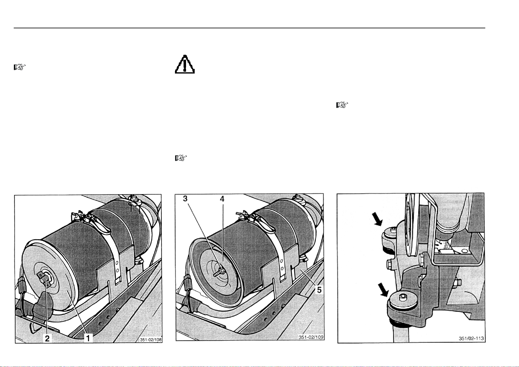
1000-hour inspection and maintenance Maintenance
Renew the air filter element, check the vacuum switch
(Every 12 months minimum or after 5 cleanings)
NOTE
The safety element* in the air filter must be changed after
5 cleanings.
- Open the engine cover.
- Unscrew the wing nut (2) and remove the air filter cover (1).
- Unscrew nut (3) and remove the air filter element (4).
* Option
ATTENTION
Thoroughly clean the inside of the air filter casing.
Do not clean with compressed air, but wipe with
a clean cloth.
- Take care not to damage the element during installation,
and be sure that the correct end is in.
- Fasten element with nut (3) and mount the filter cover.
- Remove the hose (5) from the air inlet.
- With the engine running, slowly close the air filter intake
opening (eg with a cardboard or metal plate) until the air
filter restricted warning light in the composite instrument
lights up.
To prevent damage, do not close the opening further after
the warning light illuminates.
NOTE
If the air filter restriction indicator light is not illuminated,
please contact your authorised distributor.
- Refit the hose (5).
Check the engine mounting for condition
and tightness
The flexible engine mountings are subject to great stresses.
Depending on the operating conditions, their service life is
limited.
- Check the rubber mounts for cracks and replace, if
necessary.
NOTE
Please contact your authorised distributor.
351 807 1301.0407
Page 72
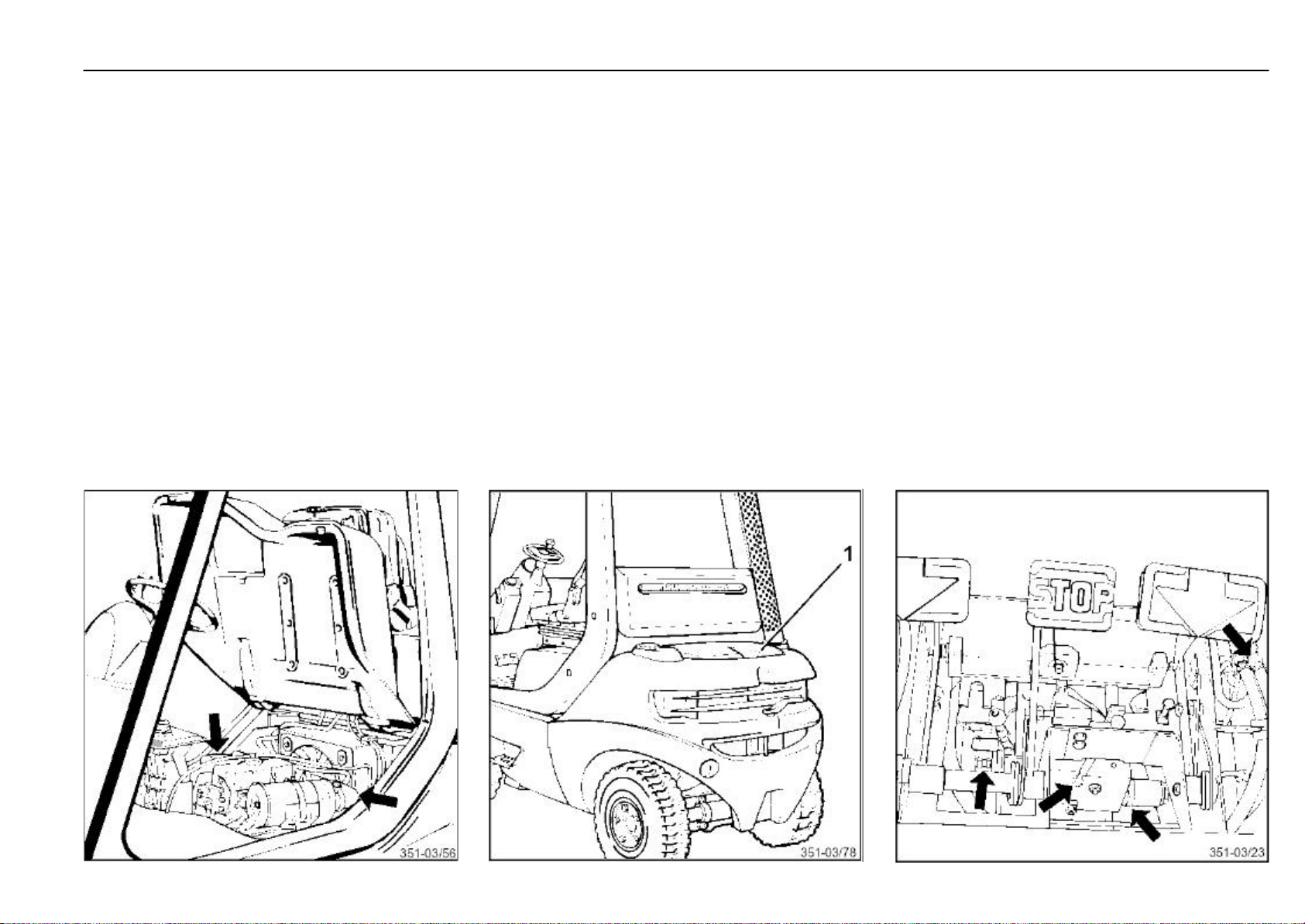
1000-hour inspection and maintenance Maintenance
Check the air intake and exhaust pipes for
leaks
- Check the combustion air hoses on the air filter for
condition and tightness. If necessary, re-tighten hose
clamps and replace any porous hoses.
- Examine the air intake and exhaust manifolds at the
cylinder head. If they prove not to be tight, retighten the
fastening bolts or replace the gaskets.
- Inspect the exhaust pipe for leaks at the manifold and
tighten the fastening screws or renew the gasket, if
necessary.
351 807 1301.0407
- Remove the cover (1) at the counterweight.
- Check the mounting, connections and air tightness of the
exhaust pipe in the counterweight, tightening the mounting screws if necessary.
- Install the counterweight cover.
Check the hydraulic system, compact axle,
pumps, valves and lines for leaks
- Remove the floor plate.
- Examine all connections between the oil reservoir, compact axle, pumps and control valves for leaks. Tighten any
loose connections.
- Inspect the lift, tilt and steering cylinders for leaks.
- Replace any porous hoses.
- Examine pipes and hoses for chafe marks and replace,
if necessary.
Page 73
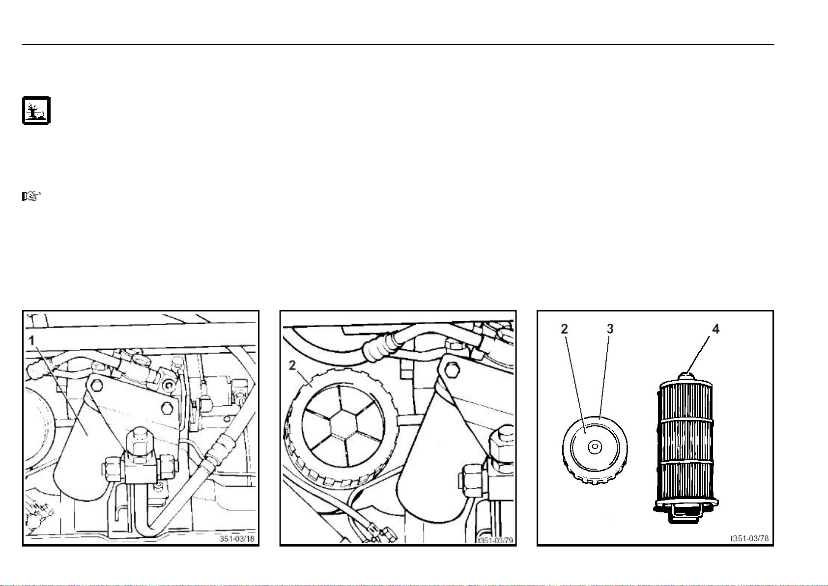
1000-hour inspection and maintenance Maintenance
Hydraulic system: Renew the pressure, suction, and breather filters
Renew the pressure filter
ATTENTION
Follow the precautions for handling fuels and lubricants.
- Lower the front cover.
- Lower the mast
- Loosen filter housing (1) with a filter spanner.
- Remove the filter with the hand.
NOTE
Place a clean cloth beneath the filter to collect any hydraulic oil flowing out.
- Fill the new filter with oil and coat the seal with oil.
- Install the filter and tighten the filter approx. 3/4 of a turn
after the seal contacts the filter housing. Use a strap-type
spanner.
- Check the filter flange for leaks in a trial run.
Renew the suction filter
- Remove the front cover.
- Loosen and remove the filter cover (2).
- Draw out the filter element (4) slowly so that the oil can
flow back into the tank.
- Then draw out the filter completely.
- Carefully insert a new filter element into the filter bowl.
- Clean the seal (3) on the filter cover (2) and coat it with oil.
- Refit the filter cover (2).
- The hydraulic system is bled automatically when the
engine is running.
- Check for leaks at the filter cover in a trial run.
- Install the front cover.
351 807 1301.0407
Page 74
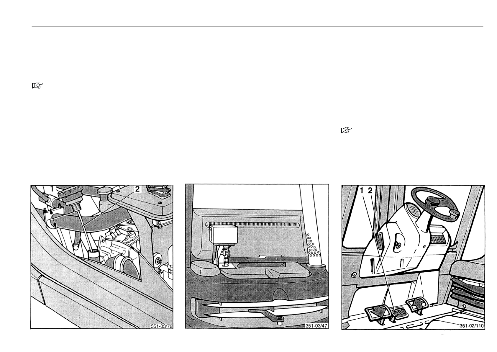
1000-hour inspection and maintenance Maintenance
Renew the breather filter
- Screw the hydraulic oil tank breather filter from the filler
neck.
- Unscrew the dipstick (2) from the breather filter (1) and
mount onto the new filter.
NOTE
In a dusty atmosphere it may become necessary to renew
the filter earlier.
- Install the floor plate.
- Close the engine cover.
351 807 1301.0407
Check the soot particulate filter system* (variant II)
- Inspect the filter mounts for security.
- Check the parts conducting exhaust gases for leaks.
- Clean the air intake tube at the burner (for this loosen the
olive fitting and remove any soot with a round wire brush).
- Check the screws on the filter casing and parts conducting exhaust gases for tightness.
Please contact your authorised distributor for these services.
* Option
Check the parking brake
Drive the lift truck with the maximum load onto a 15 % slope.
- Depress the brake pedal (1).
- Place the parking brake lever (2) in the up position. The
brake pedal will lock. The truck must not move.
- Release the parking brake lever (2). The brake pedal will
return to its initial position.
- Stop the engine.
The lift truck must not move.
NOTE
If the parking brake is not operating correctly, contact your
authorised distributor.
Page 75
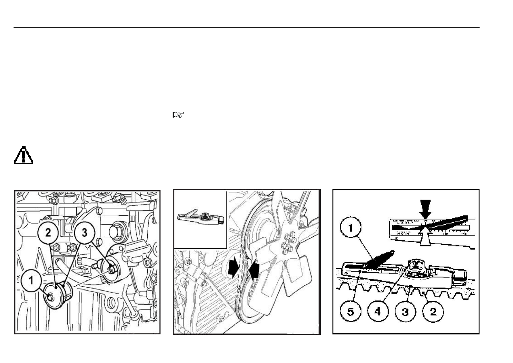
1000-hour inspection and maintenance Maintenance
Clean strainer of fuel pump
- Stop the engine.
- Open the engine cover.
- Loosen ang unscrew hexagonal nut (1).
- Remove fuel strainer cover (2) (cover and strainer, one
unit).
- Clean fuel strainer (2) with diesel fuel. Replace if necessary
- Place seal (3) in position.
- mount fuel strainer cover (2).
- Tighten hexagonal screw (1)
- Check for leaks.
ATTENTION
Keep naked flames away when working on the
fuel system. Do not smoke!
Check the V-belt
- Open the engine cover.
- Visually inspect entire V-belt for damage.
- Replace damaged V-belts.
- After installing new belts, run engine for 15 minutes, then
check belt tension.
NOTE
Chek, tension and change belts only with engine off. Refit
belt guard, if provided.
- To check tension of V-belt, use tension gauge.
- Position guide (3) on V- belt (2), midway between
pulleys, with stop against edge of belt.
- Push slowly on black pad (4) at right angles to V-belt
(2) unit spring is heard or felt to trigger.
- Carefully remove gauge without altering position of
indicator arm (1).
- Read off value where black indicator arm (1) inter
acts scale (5 arrow) .
Tension:
Pretension 450N
Retension (after engine has been runing under
load 15 minutes) 350N
- If necessary, retension belt and measure again.
351 807 1301.0407
Page 76
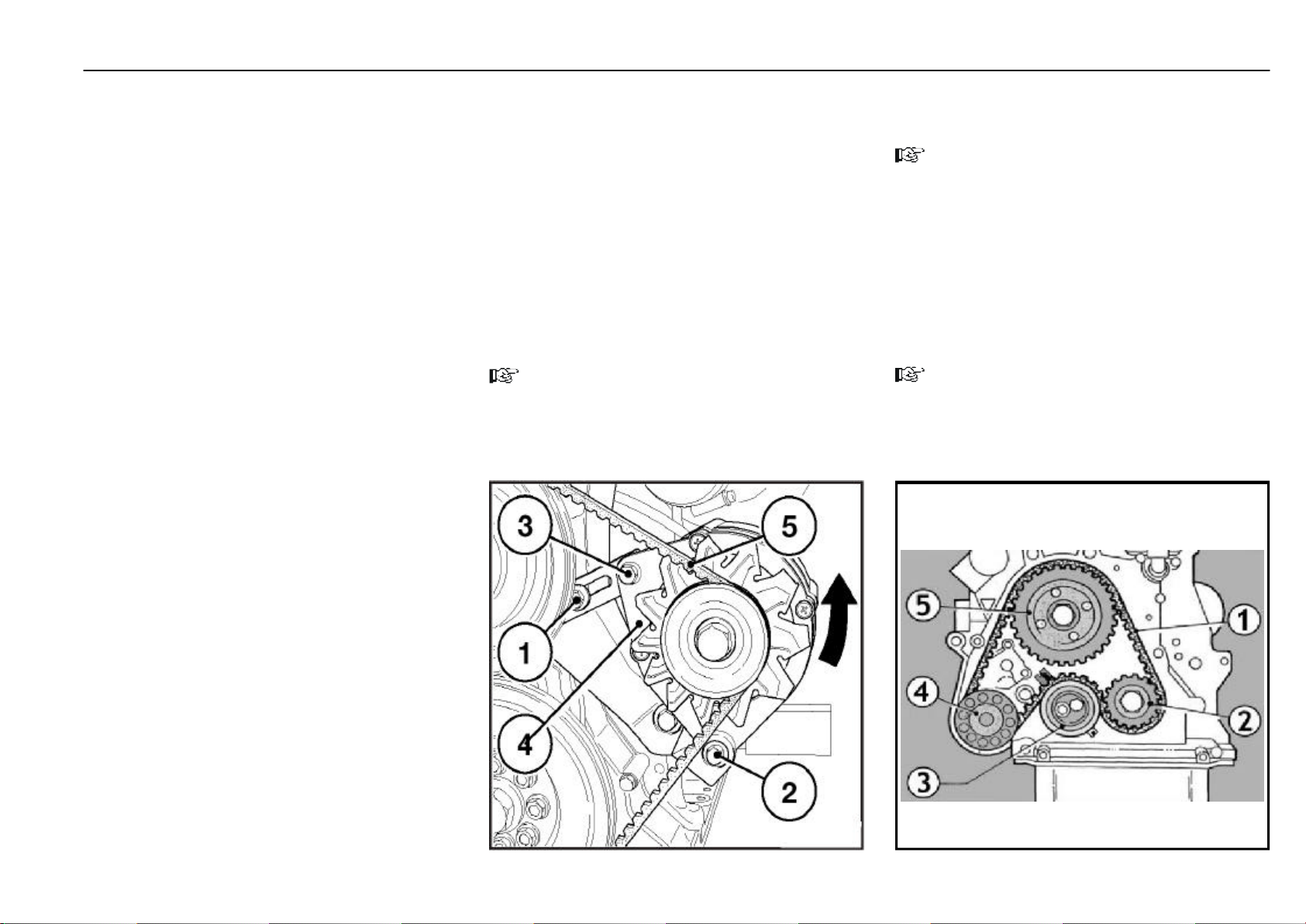
1000-hour inspection and maintenance Maintenance
351 807 1301.0407
Tighten the V-belt
- Open the engine cover.
- Slacken of bolt (1) (2) and (3).
- Adjust alternator (4) in directon of arrow by tuning bolt (3)
until correct belt tension is achieved.
Tension:
Pretension 450N
Retension (after engine has been runing under
load 15 minutes) 350N
- Retighten bolt (1) (2) and (3).
- Close the engine cover.
NOTE
Chek, tension and change belts only with engine off. Refit
belt guard, if provided.
Check and adjust the time belt and tension
pulley
NOTE
Chek, tension and change belts only with engine off.
- Open the engine cover.
- Check the time belt (1) for excessive wear, broken -out
flanks,breks and traces of oil.
- Adjust tension pulley (3) until the proper time belt tension
is achieved.
- Close the engine cover.
NOTE
As this maintenance requires special tools and skills.
Please contact your authorised dealer.
Page 77
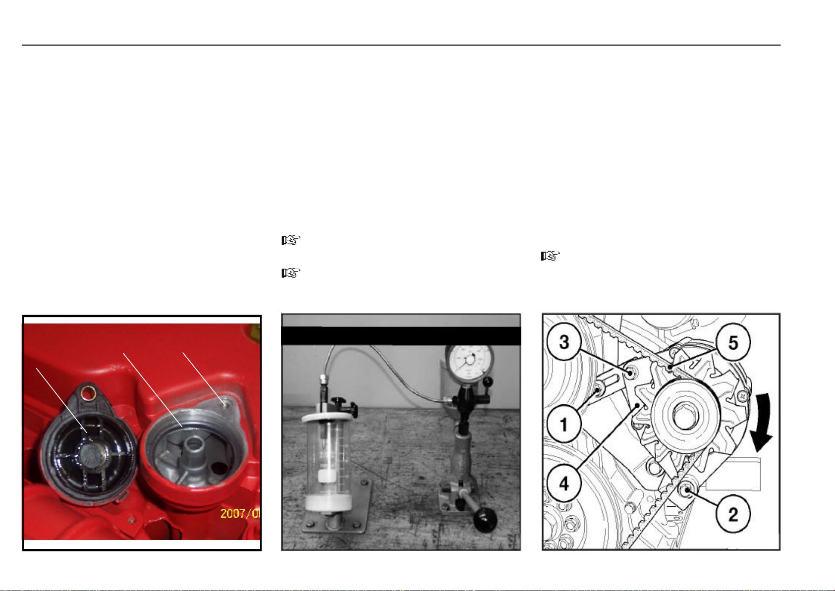
3000-hour inspection and maintenance Maintenance
Check crankcase pressure vent valve
- Open the engine cover.
- Remove the M10 bolt (1).
- Remove the ctrankcase pressure vent valve (3)
and seal (2).
- Clean the ctrankcase pressure vent valve (3)
and seal (2) use cleaning diesel oil.
- Dry the ctrankcase pressure vent valve (3)
and seal (2).
- Install the seal (2) on the ctrankcase pressure vent
valve (3).
- Install the the ctrankcase pressure vent
valve (3) with seal (2) , and screw the M10 bolt (1).
- Close the engine cover.
2
3
1
Check the injection nozzles
Open the engine cover.
- Remove the injection valve.
- Inset injection valve in holder.
- Unscrew nozzles clamping nut with long socket.
- Check the njection nozzles as belower.
- Renew any damaged njection nozzles.
- Close the engine cover.
NOTE
Do not touch the nozzle needle with your fingers.
NOTE
As this maintenance requires special tools and skills.
Please contact your authorised dealer.
Renew the V - belt
- Open the engine cover.
- Slacken of bolt (1) (2) and (3).
- Adjust alternator (4) in directon of arrow by tuning bolt (3)
to slacken belt.
- Remove and replace belt.
- Adjust alternator (4) iagainst directon of arrow by tuning
bolt (3), until correct belt tension is achieved.
- Retighten bolt (1) (2) and (3).
- Close the engine cover.
NOTE
Chek, tension and change belts only with engine off. Refit
belt guard, if provided.
351 807 1301.0407
Page 78
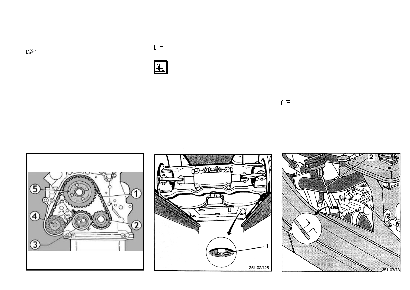
3000-hour inspection and maintenance Maintenance
Renew the time bell and tension pulley
NOTE
As this maintenance requires special tools and skills.
Please contact your authorised dealer.
351 807 1301.0407
Renew the hydraulic oil
Draining the hydraulic oil
NOTE
The fork carriage must be lowered completely.
ATTENTION
Follow the precautions for handling fuels and lubricants.
- Drive the truck over a repair pit.
- Put a container under the lift truck at the right side.
- Open the engine cover.
- Remove the breather filter with the oil dipstick (2).
- Remove the hydraulic oil drain plug (1) at the hydraulic oil
tank.
- Allow the oil to drain completely.
- Clean the area around the oil drain thoroughly.
- Re-install the drain plug.
Torque .................................................................................25 Nm
Filling/adding hydraulic oil
Capacity
- without draining the hydraulic unit............approx. 38.5 L
Total capacity:
- incl. filling of hydraulic unit.........................approx. 47.0 L
- Fill hydraulic oil at the filler opening.
- Check the oil level with the dipstick (2) and fill oil until the
upper mark on the dipstick is reached.
- Run the engine briefly and repeat the check.
NOTE
The hydraulic system is bled automatically when the engine is running.
Page 79
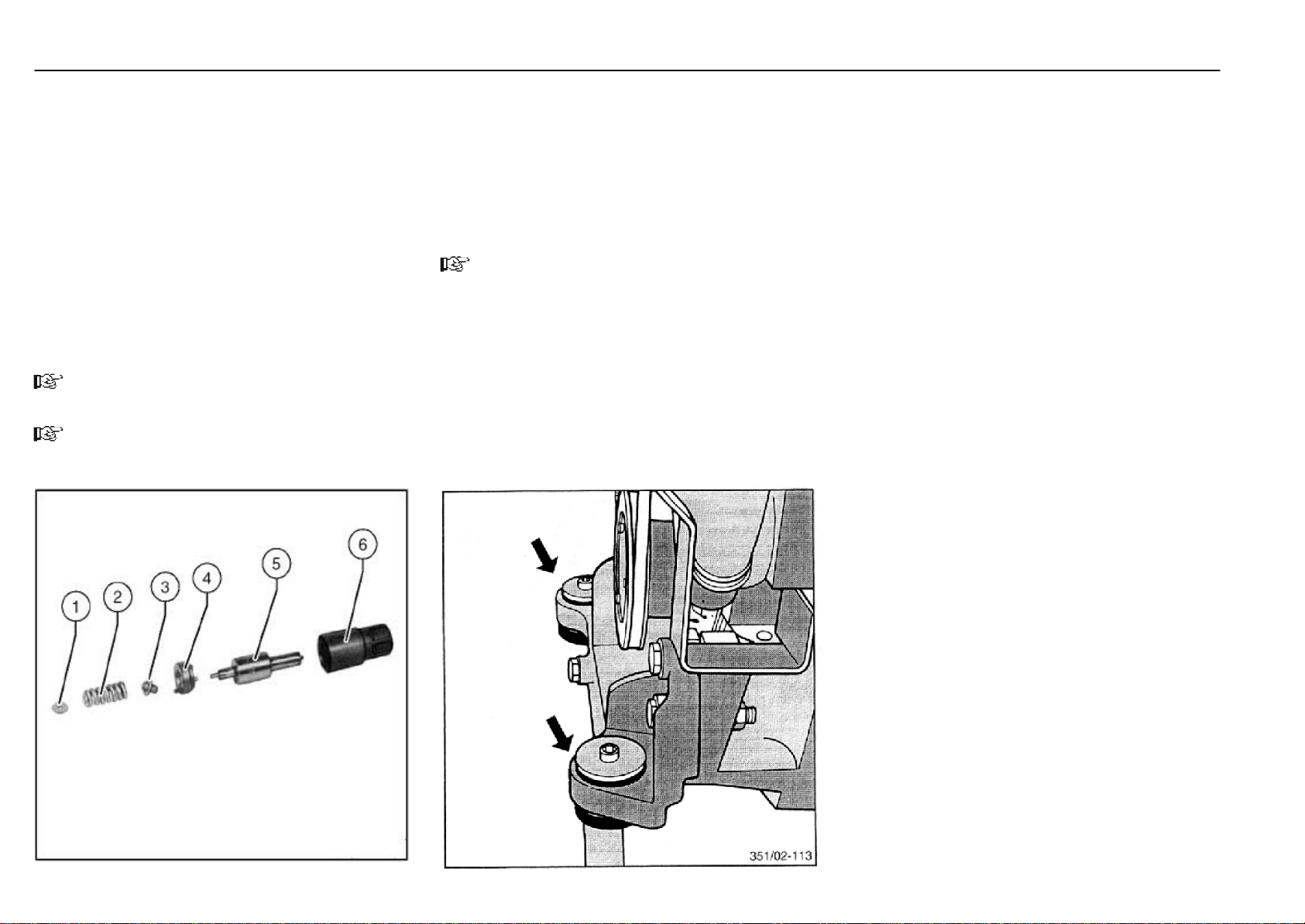
6000-hour inspection and maintenance Maintenance
Renew the injection nozzles
Open the engine cover.
- Remove the injection valve.
- Inset injection valve in holder.
- Unscrew nozzles lock nut (6) with long socket.
- Renew the njection nozzles (5).
- Complete the injection valve and install on engine
- Close the engine cover.
NOTE
Do not touch the nozzle needle with your fingers.
NOTE
As this maintenance requires special tools and skills.
Please contact your authorised dealer.
Renew the mounting of the engine
The flexible engine mountings are subject to great stresses.
Depending on the operating conditions, their service life is
limited.
- Remove the engine and renew the mounting of the
engine .
NOTE
Please contact your authorised distributor.
351 807 1301.0407
Page 80

Inspection and maintenance data Maintenance
No. Assembly Aids/Oils and lubricants Filling capacity/Settings
1 Engine Engine oil 9 L
2 Valve clearance Intake valve 0.30 mm
(with engine warm or cold) Exhaust valve 0.50 mm
3 Fuel tank Diesel fuel 45.0 L
4 Hydraulic system Hydraulic oil without filling hydraulic unit approx. 38.5 L
with filling hydraulic unit approx. 47.0 L
5 Battery Distilled water As required
6 Tyres Air See information on label on inside of
overhead guard
7 Wheel fasteners tighten front: 195 Nm
rear: 400 Nm
8 Mast and tilt cylinder pivots Lubricating grease As required
9 Lift chains, mast channels Linde chain spray As required
351 807 1301.0407
10 Fuel injection nozzle Diesel Operating pressure 210 bar
11 V-belt tension
- Fan - Alternator See page 75
See page 75
Page 81
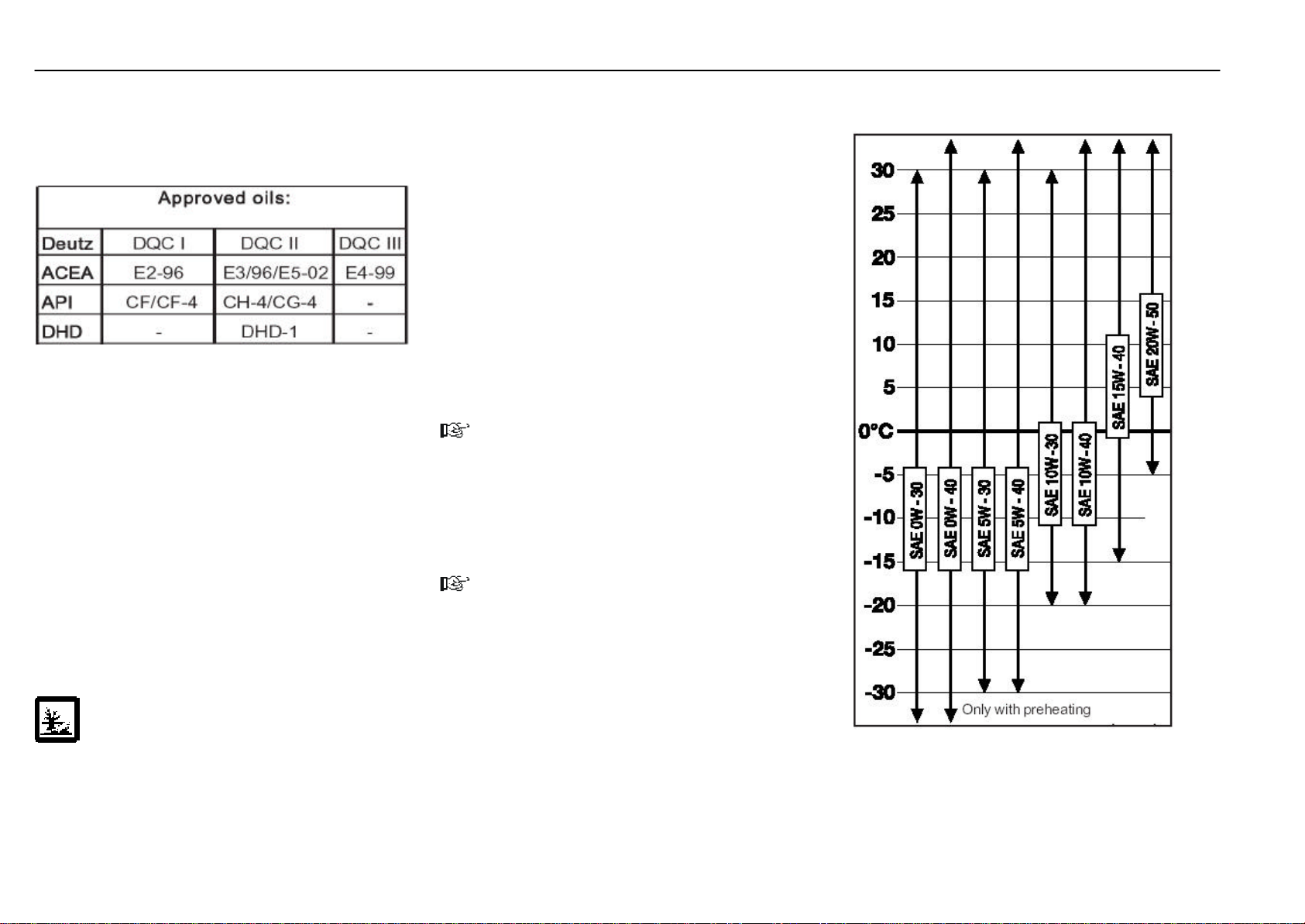
Fuel and oil recommendations
Engine oil
Lube oils are differentiated by Deatz according to their performance and quality class.
Oils of other, comparable specifications can be used.
Oil grades
Trucks equipped with a soot particulate filter should only be
operated with ash-free oils. Residues from the combustion
of additives (ash) cannot be regenerated and they will eventually clog the monolith in the long run.
During engine operation, part of the oil serving as a lubricant
for the piston is combusted ("onsumed"). The products of
combustion and the high temperatures combined lead to
"wear", particularly of the chemical oil additives. For this
reason the oil must be changed at certain intervals.
Since this oil wear depends on the operating conditions and
the quality of the oil (oil performance) and fuel used, oil
change intervals of different lengths result.
The longest possible oil change interval for lubricating oil in
the engine is one year. This means that the oil must be
renewed at least once every year, regardless of the oil
change intervals.
Oil viscosity
SAE viscosity 20W-20 (Standards of Society of Automotive
Engineering).
There are no limits to using oils with higher specifications.
Since the viscosity of lubricants varies with temperature, the
ambient temperature at the site determines the viscosity
class (SAE class) of the engine oil (see diagram). If the
ambient temperature occasionally falls below the temperature limit (e.g. using SAE 15 W-40 at -15oC/5oF), the cold start
capability of the engine can be reduced, but no damage to the
engine will result.
If the viscosity of the oil is too high, the engine will experience
starting problems. Therefore the ambient temperature when
the engine is started determines the grade of oil to be used
in winter. Seasonal oil changes can be avoided by using
multigrade oils. The specified oil change intervals also apply
to multigrade oils.
NOTE
Oil additives of any kind must not be added to any of the
above-mentioned engine oils! Their use will void the engine
warranty!
The mixing of different types of oil should be avoided.
Since the temperature ranges of adjacent SAE classifications overlap, the oil does not need to be changed when
short-term temperature fluctuations occur.
NOTE
For problem-free cold starts it is important to select the
viscosity of the engine oil (SAE grade) on the basis of the
ambient temperature when starting the engine.
At temperatures below -10 oC, SAE grade 5 W-30 engine oil
is recommended.
351 807 1301.0407
CAUTION
The used oil must be kept out of the reach of
children until disposed of in accordance with laws
and regulations. Do not allow the oil to get into the sewage
system or seep into the ground.
Due to the disposal problem, the necessary special tools
and special knowledge, have your authorised distributor
renew the engine oil and filter.
Page 82
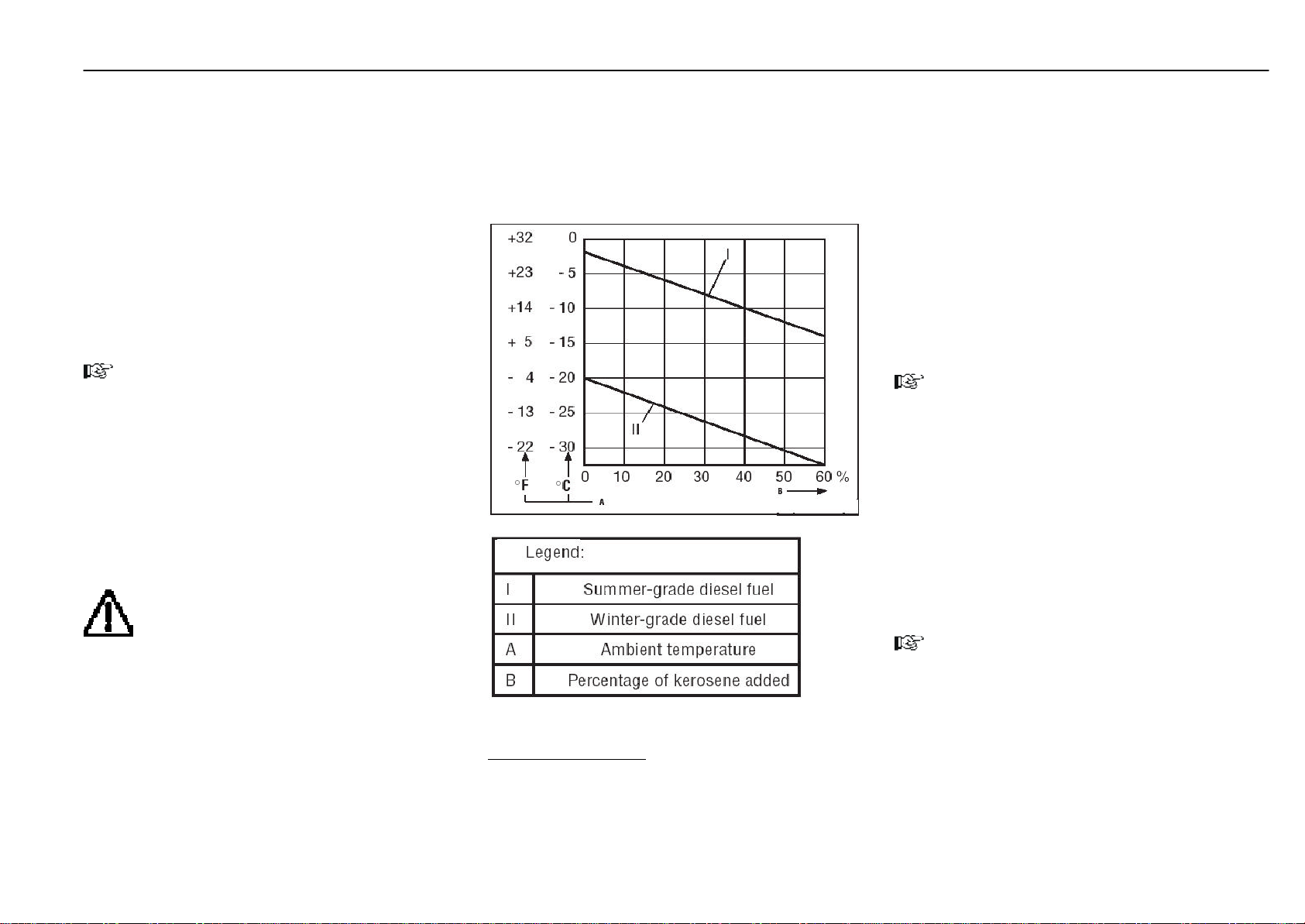
Fuel and oil recommendations
Diesel fuel
Use only Diesel fuel to EN 590 with a cetane number not
lower than 45.
The following fuel specifications / standards are approved:
- DIN EN 590
- BS 2869
- ASTM D 975-96, 1-D and 2-D
- NATO code F-54 / F-34 / F-44 and X F 63
The sulphur content should not exceed 0.5 %. If the sulphur
content is 0.5 to 1 %, the oil change intervals must be halved.
If the values are higher, contact the manufacturer of the lift
truck or the supplier of the lubricant.
NOTE
As the ambient temperature decreases, so does the viscosity of Diesel fuel due to the precipitation of paraffin. If
"summer grade" diesel fuel is used, malfunctions can
result. For this reason, "winter grade" diesel fuel that
functions reliably at temperatures down to about
-22 oC is available in the cold season of the year.
In winter, fill only winter diesel fuel to prevent any clogging
caused by paraffin precipitation. At very low temperatures you
351 807 1301.0407
must reckon with disturbing precipitations even if winter
diesel fuel is used.
Please first contact your authorised dealer.
CAUTION
For the use of plant diesel fuel (RME acc. to
DIN 51606 / preliminary norm) some important
items have to be observed.
Please first contact your authorised dealer.
Winter - grade fuel
At temperature below -15oC to - 20oC, kerosene should be
added to the diesel fuel. The relevant percentages are given
in the adjacent diagram.
If summer-grade diesel fuel must be used at temperatures
below 0oC, up to 60% kerosene canbe added ( see diagram).
Lubricating grease
Linde heavy duty grease with additives EP and MOS2.
Designation acc. to DIN 51825-KPF 2N-20 (see the Parts
Catalogue for the order number).
Any mixing with grease types other than lithium-based greas-
es is not allowed.
Hydraulic oil
Recommendation for normal duty:
Hydraulic oil ISO - L - HM 68 to ISO 6743 - 4 or HLP ISO VG 68
to DIN 51524, T.2 (factory filling), average continuous oil
temperature 60 oC - 80 oC.
Hydraulic oil recommendation for heavy duty:
Hydraulic oil ISO - L - HM 100 to ISO 6743 - 4 or HLP ISO VG 100
to DIN 51524 T.2 for heavy duty and multi-shift operation,
operation in extreme climate zones or high ambient temperatures, average continuous oil temperature over 80 oC.
For normal and heavy duty:
Hydraulic oil ISO - L - HV 68 to ISO 6743 - 4 or HVLP ISO VG 68
to DIN 51524 T.3 (multigrade oil).
NOTE
The choice of the correct oil is determined by the oil
temperature in the hydrostatic transmission.
The above-mentioned recommendations are only approximate values.
Bio hydraulic oil
Biologically fast-degradable pressure fluid
Aral Forbex SE 46
ATTENTION
Do not mix bio-oils with mineral oils. Other fluids from other
manufactures cannot be recommended.
NOTE
If in doubt, contact your authorised distributor.
Recommendations of representatives of the oil industry
should also be checked with your authorised distributor.
Only the above-mentioned oils are approved by the manu-
facturer. If other hydraulic oils are used or mixed, costly
damage can result.
Battery grease
Non-acidic grease (pole grease).
Chain spray
Linde chain spray (see the Parts Catalogue for the order
Page 83

Troubleshooting guide (Diesel engine)
Trouble Possible Cause Correction See Page
Engine will not start Fuel tank empty.
Fuel filter clogged, in winter by paraffin deposit.
Water in fuel system water preseparator.
Fuel solenoid fails to open.
Fuel line leaking.
Charging indicator light not illuminated
although lamp is okay.
Fuel pump defective.
Injection nozzles defective.
Injection pump defective.
Engine idling speed incorrect.
Engine starting performance Battery power is too low. Battery terminal
is poor loose or oxidized, causing the starter to turn
only slowly.
Fuel supply insufficient.
Restriction or air in fuel system due to paraffin
deposits in winter.
Particularly in winter:
Engine oil viscosity too high.
Refill fuel.
Renew the filter, bleed the fuel system, use winter fuel.
Drain the water preseparator.
Check for electric current with test lamp. If there is no current,
check fuse F1 and switch.
Check all pipe connections for leaks and tighten fittings.
Tighten connecting clamps at battery, check cable connections.
These faults should always be checked and corrected by skilled
staff.
Please contact your authorised distributor.
Check battery, clean battery terminals, tighten clamps and
cover with non-acidic grease.
Renew the fuel filter, bleed the fuel system. Check the fuel line
connections for leaks and tighten fittings.
Use winter fuel in the cold season.
Use engine oil appropriate for the ambient temperature.
21
61, 81
62
64, 65
351 807 1301.0407
65
62
81
80
Buzzer buzzes and the fault warning lamp blinks after switching
on the ignition switch
Fault exist in the switch lighting of the start or emergency OFF, when no illumination for the soot particulate filter system exist
Fault in soot particulate filter system
Conducting a lamp test
Switch on the ignition switch. Both warning lamps illuminate
1x short, if this is not the case, replace the warning lamps.
(Regeneration is possible, after the lamp fault has been
corrected, by pressing the fault warning button to acknowledge)
Please contact your authorised dealer.
25, 52
Page 84

Troubleshooting guide (Diesel engine)
Trouble Possible Cause Correction See Page
Engine running unevenly
with poor performance
Exhaust smokes excessively Poor compression due to burned-in or broken pis-
Idle running trouble Fuel system not in order.
351 807 1301.0407
composite instrument illuminated.
Stop the engine immediately.
ATTENTION
Engine overheating,
red warning light in
Fuel supply insufficient.
Restriction or air in fuel system due to paraffin
deposits in winter.
Injection pump overflow valve not functioning correctly.
Valve clearance not as specified.
Injection nozzles defextive.
Engine oil level too high.
ton rings or incorrect valve clearance.
Speed setting incorrect.
Oil level low.
Fan V-belt either slack or broken.
Radiator fins restricted due to dirt or foreign
objects.
Renew the fuel filter, bleed the fuel system. Check the fuel line
connections for leaks and tighten fittings.
Use winter fuel in the cold season.
Contact your authorised distributor.
Adjust valve clearance.
Contact your authorised distributor.
Drain oil to the top mark on the dipstick.
Adjust valve clearance.
Contact your authorised distributor.
Drain water preseparator and renew fuel filter. Check fuel
lines and injection lines for leaks, bleed the fuel system.
Should only be adjusted by skilled staff. Contact your authorised distributor.
Check oil system for leaks, seal if necessary.
Add oil.
Tighten or renew the V-belt.
Clean the radiator.
62
81
62
21
62
62, 71
21, 58
75
54
ATTENTION
Engine oil pressure
too low.
Stop the engine immediately.
Charging indicator light illuminated during operation
Injection system setting incorrect.
Leaks in the lubricating system.
Oil level too low.
Alternator RPM too low.
Alternator not charging the battery because alter-
nator or relay defective.
Contact your authorised distributor.
Contact your authorised distributor.
Add lubricating oil.
Contact your authorised distributor.
21, 58
75Check V-belt tension.
Page 85

Troubleshooting guide (hydraulic system)
Trouble Possible Cause Correction See Page
Abnormal noise Suction filter restricted.
Suction hoses leaking, oil foaming.
Hydraulic pump or motor failure, seals defective,
causing air intake.
Incorrect oil viscosity, low oil level in tank or in
hydraulic pump.
No or too low pressure in system
Oil pressure fluctuates
No oil flow or low oil flow Filter restricted (if accompanied by noise).
Pump suction defective, noise.
Pump failure, leakages, pressure valves do not close,
valve seat damage.
Pipe broken or leaky.
Oil of low viscosity, causing high leakage losses.
Oil temperature warning lamp illuminated.
Cause as under abnormal noise.
Pressure limiting valves or boost pressure valves
sticking.
Lift and tilt cylinders have tight spots.
Mast does not extend completely or retracts slightly
after being extended.
Pump failure, leakages, pressure limiting valves do
not close, valve seat damaged.
Pipe broken or leaky.
Valves restricted.
Hydraulic system overheating.
Renew the filter.
Tighten lines. Check oil level, top up if necessary.
Have hydraulic unit inspected by your authorised distributor.
Change oil, be sure to use the correct viscosity, top up
oil.
Change oil, top up oil.
Contact your authorised distributor.
Replace or tighten line,
Change oil, be sure to use oil of correct viscosity.
Check oil level, clean oil cooler.
See abnormal noise.
Contact your authorised distributor.
Contact your authorised distributor.
Top up hydraulic oil.
Clean or replace filter.
Contact your authorised distributor.
Replace or tighten line.
Contact your authorised dealer.
Check oil level, use specified oil, clean oil cooler, if needed.
72
71
77, 81
61, 77, 81
71
60, 77, 81
54, 61
351 807 1301.0407
61
72
71
54, 61, 81
Hydraulic oil temperature too
high
Pump failure, valves leaky.
Oil level too low or oil cooler defective.
Contact your authorised distributor.
Check oil level, if necessary top up oil. Clean cooler and check
for leaks. If defective, contact your authorised distributor.
54, 61
Page 86

Wiring diagram
1A1 Pre-heating controler
F1 Fuse, MTA Maxifuse 50 A
F2 Fuse 5 A
F3 Fuse 5 A
F4 Fuse 5 A
F5 Fuse 10 A
F7 Fuse, 5 A
F8 Fuse, MTA Maxifuse 50 A
G1 Alternator with regulator
G2 Battery 12 V
H1 Battery charging lamp, 2 W
H2 Warning, electr. control
H3 Engine oil temperature warning lamp, 1.2 W
H4 Hydraulic oil temperature
warning lamp, 1.2 W
H5 Engine oil pressure warning lamp, 1.2 W
H6 Air filter restriction warning lamp, 1.2 W
H12 Flasher indicator lamp, 1.2 W*
H13 Low fuel level warning lamp, 1.2 W
H24 Cooling fan
H25 Preheating 1.2 W
H26 Soot filter warning lamp 1.2 W*
4H1 Horn 48 W
351 807 1301.0407
9H9 Control lamp, water separator
9H10 Control lamp, water separator
K2 Starter relay
K3 Aux. relay terminal 15
R2 Glow plug
S1 Ignition switch
S2 Engine temperature switch
S3 Hydraulic oil temperature switch
S4 Engine oil pressure switch
S5 Air filter vacuum switch
S6 Fuel level warning light switch
S14 Brake pedal switch (start inhibit)
1S1 Travel direction switch*
(single-pedal model only)
4S8 Horn button
V1/V3 Decoupling diode
X1 Connector 16 pins
X2 Power connector 1 pin
X3 Connector 3 pins
7X7 Connector 2 pins, soot filter* connection
1Y3 Fuel shutoff solenoid
(a) Soot filter*
(b) Wiring diagram for optional turn signal indicator
(c) Soot filter warning*
Colour code
BU blue
BN brown
YE yellow
GN green
GY grey
RD red
BK black
WH white
VT violet
OG orange
The number before the cable colour indicates the cross
section of the cable.
Cables without indication of the cross section = 0.75 mm
2
M1 Starter 3 kW
P1 Hour meter
6P3 Composite instrument
Page 87
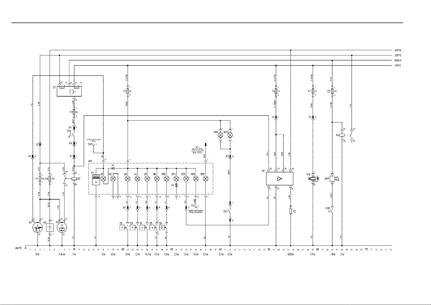
Wiring diagram
Dies ist ein Hilfsmittel
351 807 1301.0407
Page 88

Wiring diagram (options)
5E2 Dip beam, left 55 W
5E3 Dip beam, right 55 W
5E4 Side light, front left 5 W
5E5 Side light, front right 5 W
5E6 Side light, rear left 5 W
5E7 Side light, rear right 5 W
5E8 License plate light 5 W
9E21-26 Working lights 55 W
5F5 Fuse 10 A
5F6 Fuse 10 A
5F7 Fuse 5 A
5F8 Fuse 5 A
5F9 Fuse 15 A
5F10 Fuse 15 A
9F4 Fuse 10 A
9F5 Fuse 10 A
9F11 Fuse 15 A
9F12 Fuse 15 A
9F13 Fuse 15 A
5H8 Turn signal light, front left 21 W
5H9 Turn signal light, rear left 21 W
5H10 Turn signal light, front right 21 W
5H11 Turn signal light, rear right 21 W
5H18 Switch illumination 1.2 W
351 807 1301.0407
5H19 Switch illumination 1.2 W
9H3 Switch illumination 1.2 W
9H4 Switch illumination 1.2 W
9H16 Switch illumination 1.2 W
9H17 Switch illumination 1.2 W
5K1 Flasher unit
9K5 Wiper relay, front
9K6 Wiper relay, rear
9M1 Wiper motor, front 30 W
9M2 Wiper motor, rear 30 W
5X1 Connector, 8 pins
5X2 Connector, 6 pins
9X1 Connector, 6 pins
9X2 Connector, 3 pins
9X2a Connector, 3 pins
9X7 Connector, 6 pins
9X8 Connector, 6 pins
(I) Working lights
(II) Lighting
(III) Directional indicator and hazard warning system
(a) Wiring diagram, standard equipment
(IV) Wiper, front
(V) Wiper, rear
Cable colours
BU blue
BN brown
YE yellow
GN green
GY grey
RD red
BK black
WH white
VT violet
OG orange
The number before the cable colour indicates the cross
section of the cable.
Cables without indication of the cross section = 0.75 mm
2
5S11 Light switch
5S12 Hazard warning light switch
5S13 Turn signal switch
9S1 Front working light switch
9S2 Rear working light switch
9S3 Wiper switch, front
9S4 Wiper switch, rear
Page 89
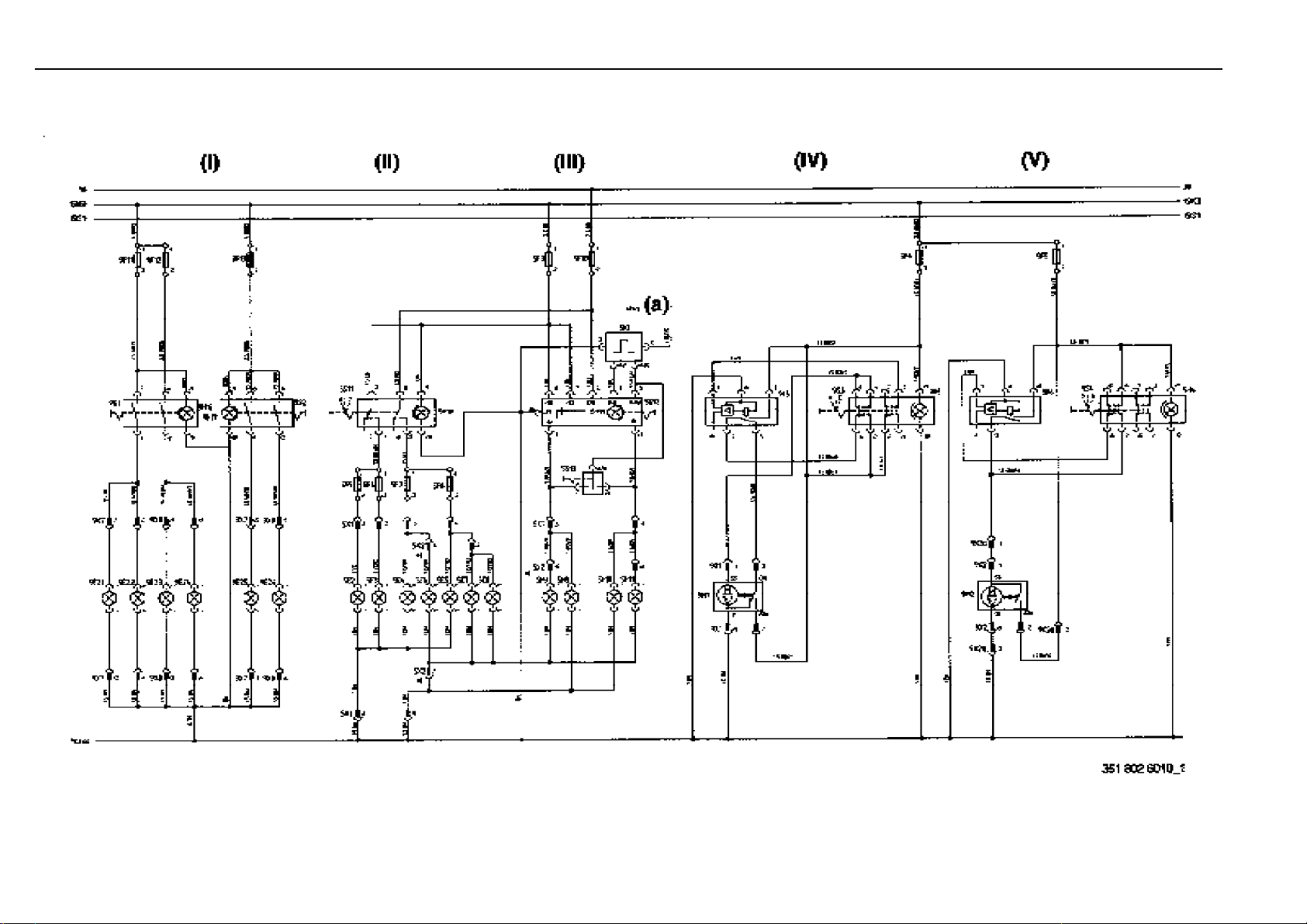
Wiring diagram (options)
351 807 1301.0407
Page 90

351 807 1301.0407
Page 91

Hydraulic circuit diagram
A Service hydraulics
1 Working cylinder (auxiliary hydraulics)
2 Working cylinder (auxiliary hydraulics)
3 Tilt cylinder
4 Slow lowering valve
5 Standard mast
6 Duplex mast
7 Triplex mast
8 Control valve block assy. comprising:
9 Directional control valve - auxiliary hydraulics
10 Directional control valve - auxiliary hydraulics
11 Pressure holding valve (pilot controlled)
12 Directional control valve - tilting
13 Directional control valve - lifting
14 Pressure reducing valve
15 2/2-way valve (pressure balance)
16 Pressure relief valve
Standard Duplex Triplex
H 25 175 +5 bar 175 +5 bar 185 +5 bar
H 30 200 +5 bar 200 +5 bar 205 +5 bar
17 Check valve
18 Shuttle valve
B Shuttle valve
C Check valve 1 bar
D Oil cooler
E Steering control valve comprising:
19 Maximum pressure valve 120 +5 bar H 20 - 30
20 Steering control valve
21 Suction valve
22 Hose safety valve 180
+20
bar H 25 - 30
G Compact axle AK 30-02 assembly com-
prising:
23 Directional control valve, selection of direction (sin-
gle-pedal model)*
24 Bypass valve (towing device)
25 Pressure reducing valve 4 - 10 bar
26 4/3-way valve travel direction
27 Pressure relief valve 11 bar
28 2/2- way valve 12 bar
29 3/2- way valve - speed control signal
30 5/3- way valve - brakes
31 2/2- way valve 5 bar (lock-out logic)
32 Slave piston
33 3/2- way valve (lock-out logic)
34 Boost pressure valve 17.5 bar
35 Pilot valve
36 Control piston
37 Variable-displacement pump
38 Hand pump - release of multiple disc brake
39 Fixed-displacement hydraulic motor
40 Maximum pressure valve
41 Multiple disc brake
L Tandem pump assembly comprising:
42 Check valve
43 Priority valve 21 l/min
44 2/2-way valve
45 Gear pump
46 Gear pump
H Oil filter, 9 μm rating
J Control piston speed control 5-14 bar
K Engine
n = 800 ... 2100 rpm (H 20 - 30)
M Suction filter 0.25 bar, 15 μm
N Oil tank with:
47 Breather filter with suction and pressurising valve
0.35
+0,15
bar
351 807 1301.0407
F Steering axle
* Option
Page 92
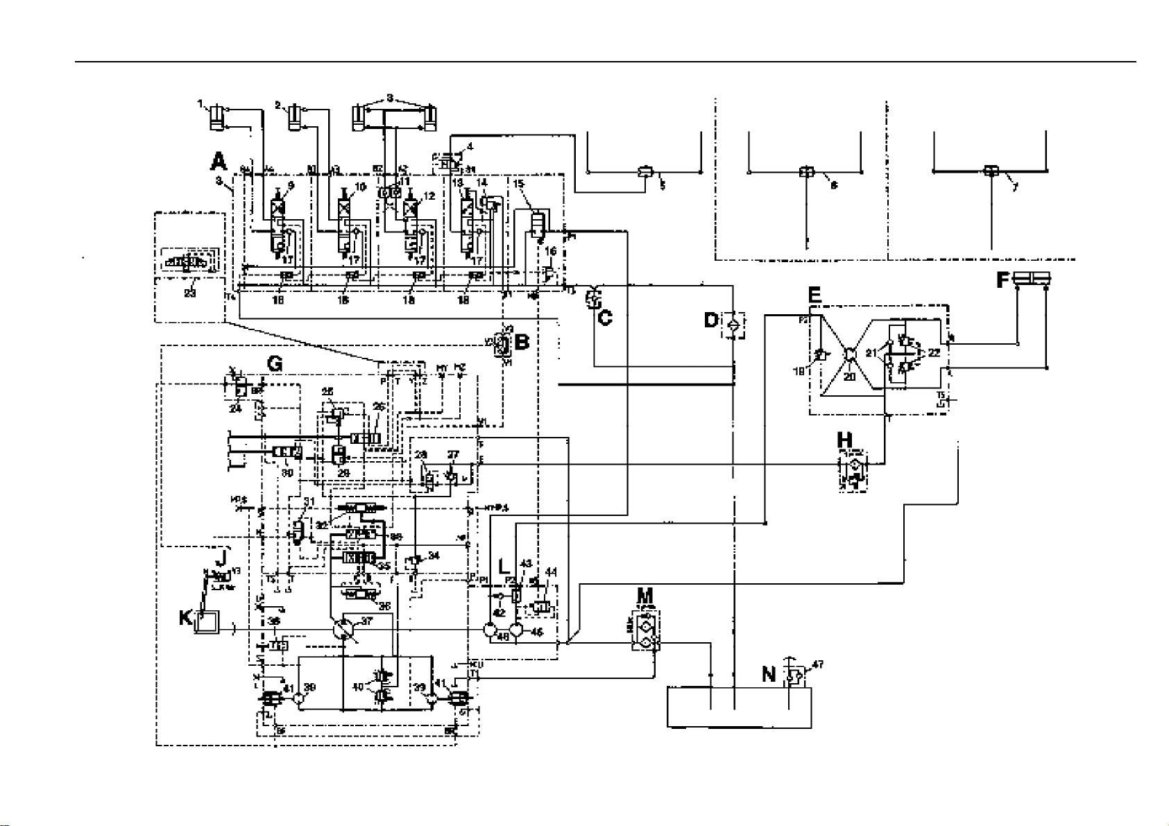
Hydraulic circuit diagram
351 807 1301.0407
351 802 0252b
Page 93

Linde (China) Forklift Truck Com.Ltd
No. 89 JInshang Road,
Xiamen 361009
P.R .China
Tel +86 -592- 5533800
Fax +86 -592- 5533381
351 807 1301 0407
351 807 1301.0407
 Loading...