

Lincoln Quicklub Maintenance Manual
Quicklub
®
Maintenance
ASC FORM# 80-1088
REV 7/11/2014
2/16/2009

Contents
Pages
Introduction------------------------------------------------------------------------------------------ 3
Benefits from Automated Lubrication ------------------------------------------------------ 3
The Lincoln Quicklub Pump-------------------------------------------------------------------- 3
Glossary of Terms--------------------------------------------------------------------------------- 4 - 5
System Operation (Non-Monitored) --------------------------------------------------------- 6
System Operation (Monitored) ----------------------------------------------------------------7
Divider Valve Operation ------------------------------------------------------------------------- 8
System Startup ------------------------------------------------------------------------------------- 9
Daily Walk-Around Inspection----------------------------------------------------------------- 10
Troubleshooting Guide -------------------------------------------------------------------------- 11
Troubleshooting a Blockage ------------------------------------------------------------------- 12 – 13
Quick-Fill (Filling Reservoir) ------------------------------------------------------------------- 14
Monitored Pump PC Board indicator LED’s ---------------------------------------------- 15
Non-monitored Pump PC Board indicator LED’s --------------------------------------- 16
Pushbutton Fault Light Indicator ------------------------------------------------------------- 17
Manually Lubricating Bearings --------------------------------------------------------------- 18
Remote Lube Fitting ------------------------------------------------------------------------------19
Spiral Wrap (Protection for lube lines)------------------------------------------------------ 20
Special Guarding (Protection for lube lines)---------------------------------------------- 21- 22
Tapping Lubrication Points -------------------------------------------------------------------- 23
2/13/09
2

Introduction
This manual has been assembled to assist the operator in understanding and maintaining the Lincoln
Quicklub system. It should be reviewed periodically so the operator becomes familiar with the nuances
of the lube system. The manual shows some details about a typical installations followed by system
maintenance and trouble shooting techniques.
The manual has a section that shows how our progressive lube system operates. A schematic diagram
shows how the lube progresses from the pump to the primary valves, then to the secondary valves and
finally to the bearing points.
When a Lincoln lube system is installed, quality and system robustness is the number one priority.
Quicklub lubrication systems are proven to increase the life of pins and bushings, and decrease labor
costs associated with manual lubrication. When a system is installed, items such as machine
articulation, type of material machine handles, climate, and other operating conditions that could
damage the system are taking into consideration.
Benefits From Automatic Lubrication
• Gain 30 to 45 minutes per day of increased productivity for each machine by lubricating while
machine is in service.
• Improve bearing life and reduce maintenance downtime due to repairing damaged bearings.
• Reduce bearing wear by delivering smaller, more frequent amounts of grease to each bearing.
• Reduce grease consumption by delivering the required amount of grease.
• Improve safety by eliminating the daily practice of climbing all over machinery to lubricate
bearings. This can be extremely difficult in severe weather conditions.
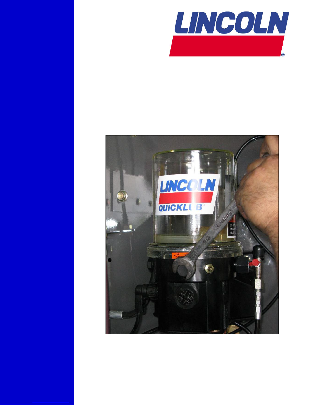
The Lincoln Quicklub Pump
Designed for the harsh environment of the construction markets, Quicklub pumps are loaded with
features:
• Available in 12, 24 VDC and 120 VAC.
• Capable of dispensing #2 grease (oil systems available)
• Optional low-level alarms and system operation alarms with warning lights in the cab.
• Reservoir (2-, 4-, 8- or 15-Liter) can be refilled through a grease fitting, typically every 150-300
hours of operation.
• All pumps have high-pressure capability to ensure grease is delivered to each component.
• A blocked lube point can be detected at the pump or in the cab with the optional alarm and
warning light. A buzzer can also be added as an alarm.
• Pump controls run-time and built-in-timer.
• Data Logger models available that store information on system operation history and can be
connected to “Produce Link/GPS” to remotely notify if the system requires service.
2/13/09
3
Glossary of Terms
Automated Lubrication System (ALS) – A pump supplies a number of bearings with lubricant via a
system of transmission lines and divider valves.
Closure Plug – A threaded plug used to purposely block lubricant from exiting a valve outlet. This
lubricant will move down to the next outlet.
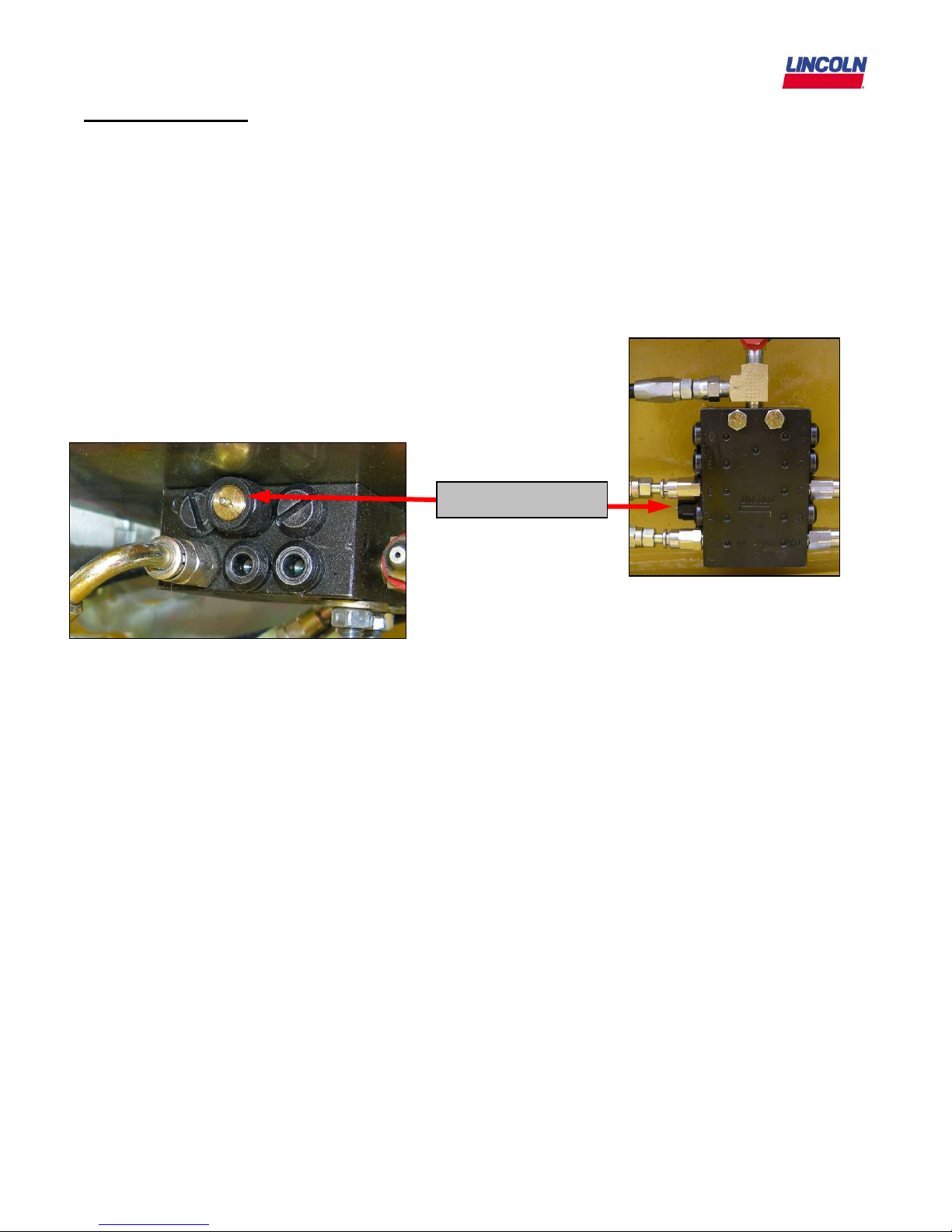
Cycle Indicator Pin – Visual indication pin attached to a valve piston on the divider valve (see below).
The pin is located on the side of the divider valve that moves in and out as grease flows within the
valve. A cycle indicator pin is not necessarily present on all divider valves. Divider valves without cycle
indicator pins are available.
Cycle Indicator Pin
Cycle Rate – Amount of time it takes for every valve to cycle at least once.
Distribution block – See divider valve
Divider Valve – A Quicklub
®
divider valve is a proportioning device consisting of a minimum of three
pistons. A primary divider valve is the first divider valve downstream from the lube pump. A secondary
divider valve is any divider valve receiving lubricant from the primary divider valve. (A.k.a. distribution
block, metering valve or SSV valve)
Feed Line – Tubing or hose going from a divider valve directly into a terminating lubrication fitting.
Fitting – Hardware used to connect hose or tube to lubrication port on equipment.
Lube Event – Depending on the Quicklub
®
pump that is used, it is the duration the pump is pumping
grease. On a monitored pump, the lube event duration is controlled by a proximity switch. On the nonmonitored pumps, the lube event duration is controlled by setting the “on” and “off” times via the dials
on the PC board.
Metering Valve – See divider valve.
Monitored Pump – A Quicklub
®
pump that utilizes a proximity switch to monitor and end the lube
event. The pump requires that the “off time” be set on the PC board, which is accessible from the front
side of the pump. The “off time” is the length of time between lube events (pump operation).
2/13/09
4

Non-monitored pump - A Quicklub
switches on the PC board, which is accessible from the front side of the pump. The operation of the
pump relies solely on the internal timer and its dial settings.
Outlet - Each outlet on a Quicklub
the lubricant will be diverted to the next outlet down allowing proper proportioning of lubricant to all
lubrication points.
Pressure Relief Valve – Located at the outlet side of each pump element. It is a valve that limits the
pressure in the system to a maximum value (3500psi). If pressure from the pump exceeds this value,
the valve opens and lubricant is bled off to the atmosphere. A blockage in the system will cause an
elevated pressure in the system.
Primary Divider Valve – First divider valve downstream from the lube pump, distributes lube to
secondary valves.
Proximity Switch – A switch device that can be inserted into a divider valve and triggered by the piston
movement inside the valve. A cycle consists of the piston moving two times (out and back).
Pushbutton – Optional accessory on Quicklub systems that alerts the operator of a fault and allows the
operator to trigger an additional lubrication cycle. Usually mounted in the cab for visibility.
Secondary divider valve – Any divider valve receiving lubricant from the primary divider valve.
SSV Valve – See divider valve.
SSV-D Valve – A divider valve with adjustable outputs.
Supply Line – Hose from the pump to primary valve and hose from the primary valve to any secondary
valve.
®
pump that has it’s “on” and “off” time set by the red and blue dial
®
divider valve dispenses .012 in³ per cycle. If an outlet is plugged,
2/13/09
5

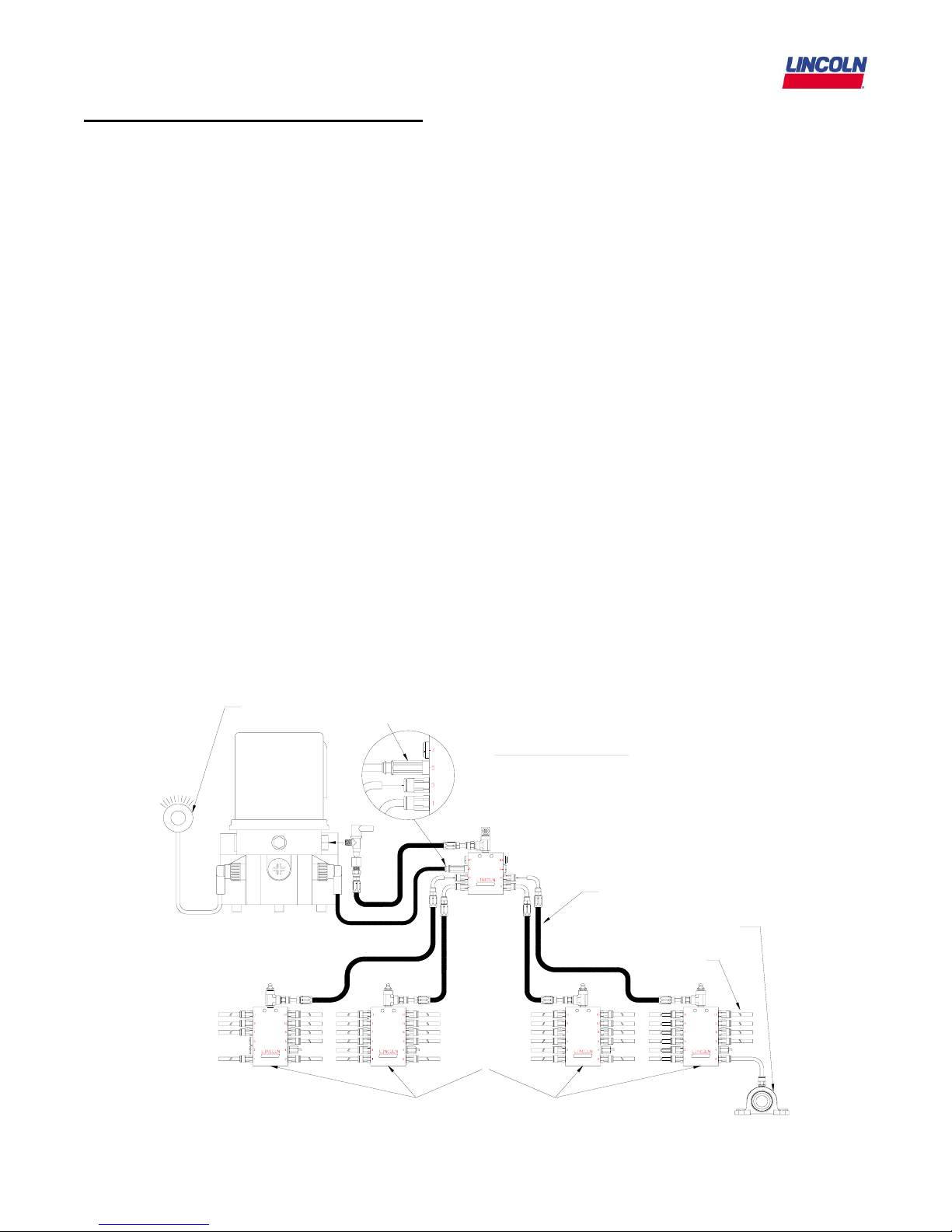
System Operation (Non-Monitored System)
The key components of the Quicklub Non-Monitored system are:
1. Pump with an Integrated Timer. The Integrated timer controls the “On Time” and “Off Time”
of the pump.
2. Divider valve network consisting of a Primary Valve and Secondary Valves with attached Cycle
Indicator Pin.
3. A lubrication event is initiated by actuating the pump via the Integrated Timer based on a
preset “pause time” or time between lubrication events.
4. The Pump dispenses lubricant to the primary divider valve.
5. The Primary Valve distributes the lubricant to the secondary valves.
6. The Secondary Valves distribute and dispense lubricant to the lubrication points.
7. Lubricant flow through the divider valves actuates the Cycle Indicator Pin for a visual
inspection of proper operation.
8. The pump will run for the preset On-Time
9. The controller now begins countdown for the next lubrication event.
Pump
Non-Monitored System
Closure Plug
Outlet Fitting
Primary
Divider
Valve
Secondary
Divider
Valves
Cycle Indicator Pin
Hose
Lube Point
Tubing
2/13/09
6
System Operation (Monitored System)
The key components of the Quicklub Monitored system are:
1. Pump with an Integrated Timer. The Integrated timer controls the “Off Time” of the pump.
2. Divider valve network consisting of a Primary Valve and Secondary Valves with attached Cycle
Indicator Pin.
3. A lubrication event is initiated by actuating the pump via the Integrated Timer based on a
preset “pause time” or time between lubrication events.
4. The Pump dispenses lubricant to the primary divider valve.
5. The Primary Valve distributes the lubricant to the secondary valves.
6. The Secondary Valves distribute and dispense lubricant to the lubrication points.
7. Lubricant flow through the divider valves actuates the Cycle Indicator Pin for a visual
inspection of proper operation.
8. The pump will run until the proximity switch reads one full cycle of the piston. The proximity
switch can be attached to any block outlet in the system.
9. The timer now begins countdown for the next lubrication event.
10. The Pushbutton/Fault light will blink if the pump reservoir is low on grease or if there is a
blockage in the system.
Pushbutton/
Fault Light
Proximity
Sensor
Pump
R3 Valve
2/13/09
Monitored System
Primary
Divider
Valve
Secondary
Divider
Valves
7
Hose
Lube Point
Hose
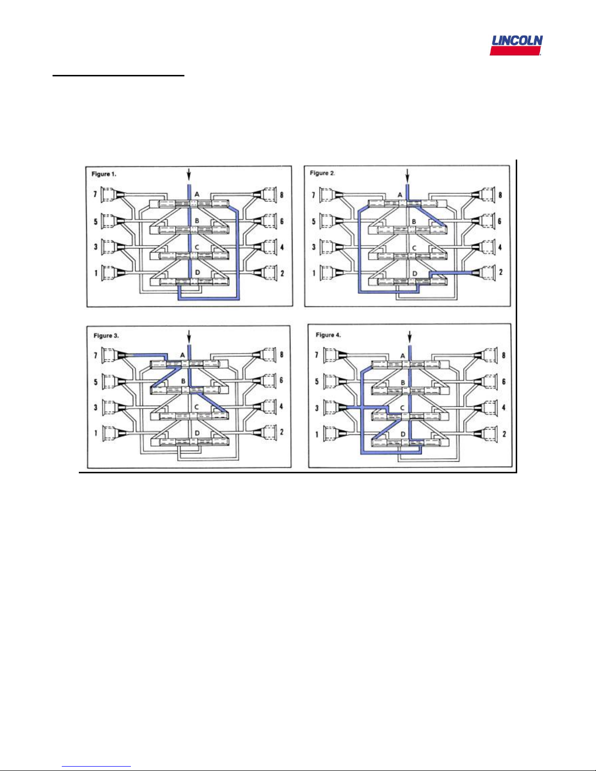
Divider Valve Operation
At the heart of every Quicklub System is the metering valve or progressive distributor block, designed
to positively meter the input of lubricant (oil up to NLGI #2 greases) out to the connected number of
lubrication points irrespective of distance and back pressure. The inlet passageway is connected to all
piston chambers at all times with only one piston free to move at any one time.
• With all pistons at the far right, lubricant from the inlet flows against the right end of piston A (fig. 1).
• Lubricant flow shifts piston A from right to left, dispensing piston A output through connecting
passages to outlet 2. Piston A shift directs flow against right side of piston B (fig. 2).
• Lubricant flow shifts piston B from right to left, dispensing piston B output through valve ports of
piston A and through outlet 7 (fig. 3).
• Lubricant flow shifts piston C from right to left dispensing piston C output through valve ports of
piston B and through outlet 5.
• Piston C shift directs lubricant flow against right side of piston D (not illus.)
• Lubricant flow shifts piston D from right to left, dispensing piston D output through valve ports of
piston C and through outlet 3.
• Piston D shift directs lubricant through connecting passage to the left side of piston A (fig. 4).
• Lubricant flow against left side of piston A begins the second half cycle which shifts pistons from left
to right, dispensing lubricant through outlets 1, 8, 6 and 4 of the divider valve.
2/13/09
8
 Loading...