

Page 1

Operator’s
P
O
W
E
R
M
anual
W
A
V
E
®
S
3
5
0
&
For
u
se
11694,
S
wi
t
h
3
5
m
ach
i
n
es
11753,
0
A
h
avi
n
L
U
g
Cod
e
Nu
11782,
M
m
b
er
I
N
s:
12371
U
M
R
egi
ster
y
our
www.
linc
olne
le
c
A
uthori
z
ed
S
erv
www.
linc
olne
le
c
Save for
Da
Code: (ex: 10859)
Serial: (ex: U1060512345)
IM10061-D
© Lincoln Global, Inc. All Rights Reserved.
te Purc
futur
ha
se
d
e reference
| Issue D ate July-16
m
t
t
achi
r
ic
i
ce
r
ic
.
.
c
c
ne:
om
and
om
/
/
r
e
loc
gis
Di
a
t
e
stri
t
or
r
butor
Locator:
Ne
e
d
He
lp
?
Ca
ll 1
.8
8
8
.9
3
5
.3
8
7
7
to
ta
l
k
to
a
S
e
rv
i
c
e
Re
p
re
s
e
n
ta
ti
v
e
Ho
u
rs
o
f Op
e
ra
tio
n
:
8
:0
0
A
M
to
6
:0
0
P
M
(
E
T
)
M
o
n
. th
ru
F
ri
.
After hours?
Use “Ask the Experts” at lincolnelectric.com
A Lincoln Service Representative will contact you
no later than the following business day.
For Service outside the USA:
Email: globalservice@lincolnelectric.com
Page 2
THANK YOU FOR SELECTING
A QUALITY PRODUCT BY
LINCOLN ELEC TRIC.
PLEASE EXAMINE CARTON AND EQUIPMENT FOR
DAMAGE IMMEDIATELY
When this equipment is shipped, title passes to the purchaser
upon receipt by the carrier. Consequently, claims for material
damaged in shipment must be made by the purchaser against the
transportation company at the time the shipment is received.
SAFETY DEPENDS ON YOU
Lincoln arc welding and cutting equipment is designed and built
with safety in mind. However, your overall safety can be increased
by proper installation ... and thoughtful operation on your part.
DO NOT INSTALL, OPERATE OR REPAIR THIS EQUIPMENT
WITHOUT READING THIS MANUAL AND THE SAFETY
PRECAUTIONS CONTAINED THROUGHOUT. And, most importantly,
think before you act and be careful.
WARNING
This statement appears where the information must be followed
exactly to avoid serious personal injury or loss of life.
CAUTION
This statement appears where the information must be followed
to avoid minor personal injury or damage to this equipment.
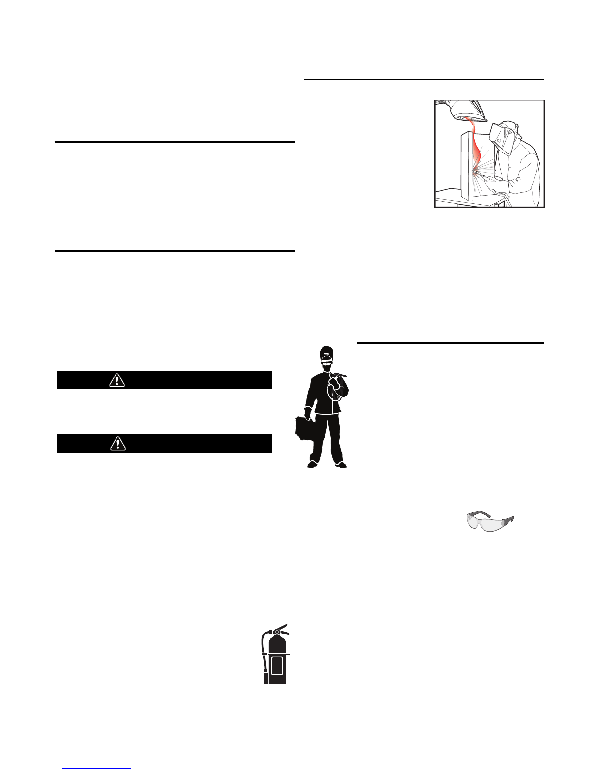
KEEP YOUR HEAD OUT OF THE FUMES.
DON’T get too close to the arc.
se corrective lenses if necessary
U
to stay a reasonable distance
away from the arc.
READ and obey the Safety Data
Sheet (SDS) and the warning label
that appears on all containers of
welding materials.
USE ENOUGH VENTILATION or
exhaust at the arc, or both, to
keep the fumes and gases from
your breathing zone and the general area.
IN A LARGE ROOM OR OUTDOORS, natural ventilation may be
adequate if you keep your head out of the fumes (See below).
USE NATURAL DRAFTS or fans to keep the fumes away
from your face.
If you de velop unusual symptoms, see your supervisor.
Perhaps the welding atmosphere and ventilation system
should be checked.
WEAR CORRECT EYE, EAR &
BODY PROTECTION
PROTECT your eyes and face with welding helmet
properly fitted and with proper grade of filter plate
(See ANSI Z49.1).
PROTECT your body from welding spatter and arc
flash with protective clothing including woolen
clothing, flame-proof apron and gloves, leather
leggings, and high boots.
PROTECT others from splatter, flash, and glare
with protective screens or barriers.
IN SOME AREAS, protection from noise may be appropriate.
BE SURE protective equipment is in good condition.
Also, wear safety glasses in work area
AT ALL TIMES.
SPECIAL SITUATIONS
DO NOT WELD OR CUT containers or materials which previously
had been in contact with hazardous substances unless they are
properly cleaned. This is extremely dangerous.
DO NOT WELD OR CUT painted or plated parts unless special
precautions with ventilation have been taken. They can release
highly toxic fumes or gases.
Additional precautionary measures
PROTECT compressed gas cylinders from excessive heat,
mechanical shocks, and arcs; fasten cylinders so they cannot fall.
BE SURE cylinders are never grounded or part of an
electrical circuit.
REMOVE all potential fire hazards from welding area.
ALWAYS HAVE FIRE FIGHTING EQUIPMENT READY FOR
IMMEDIATE USE AND KNOW HOW TO USE IT.
Safety 01 of 04 - 06/15/2016
Page 3
SECTION A:
WARNINGS
CALIFORNIA PROPOSITION 65 WARNINGS
Diesel Engines
Diesel engine exhaust and some of its constituents are known
to the State of California to cause cancer, birth defects, and other
reproductive harm.
Gasoline Engines
The engine exhaust from this product contains chemicals known
to the State of California to cause cancer, birth defects, or other
reproductive harm.
ARC WELDING CAN BE HAZARDOUS. PROTECT
YOURSELF AND OTHERS FROM POSSIBLE SERIOUS
INJURY OR DEATH. KEEP CHILDREN AWAY.
PACEMAKER WEARERS SHOULD CONSULT WITH
THEIR DOCTOR BEFORE OPERATING.
Read and understand the following safety highlights. For
additional safety information, it is strongly recommended
that you purchase a copy of “Safety in Welding & Cutting ANSI Standard Z49.1” from the American Welding Society,
P.O. Box 351040, Miami, Florida 33135 or CSA Standard
W117.2-1974. A Free copy of “Arc Welding Safety” booklet
E205 is available from the Lincoln Electric Company,
22801 St. Clair Avenue, Cleveland, Ohio 44117-1199.
BE SURE THAT ALL INSTALLATION, OPERATION,
MAINTENANCE AND REPAIR PROCEDURES ARE
PERFORMED ONLY BY QUALIFIED INDIVIDUALS.
SAFETY
1.d. Keep all equipment safety guards, covers
and devices in position and in good repair.
Keep hands, hair, clothing and tools away
from V-belts, gears, fans and all other
moving parts when starting, operating or
repairing equipment.
1.e. In some cases it may be necessary to remove safety guards to
perform required maintenance. Remove guards only when
necessary and replace them when the maintenance requiring
heir removal is complete. Always use the greatest care when
t
working near moving parts.
1.f. Do not put your hands near the engine fan. Do not attempt to
override the governor or idler by pushing on the throttle control
rods while the engine is running.
1.g. To prevent accidentally starting gasoline engines while turning
the engine or welding generator during maintenance work,
disconnect the spark plug wires, distributor cap or magneto wire
as appropriate.
1.h. To avoid scalding, do not remove the radiator
pressure cap when the engine is
hot.
ELECTRIC AND
MAGNETIC FIELDS MAY
BE DANGEROUS
2.a. Electric current flowing through any conductor
causes localized Electric and Magnetic Fields (EMF).
Welding current creates EMF fields around welding cables
and welding machines
FOR ENGINE POWERED
EQUIPMENT.
1.a. Turn the engine off before troubleshooting
and maintenance work unless the
maintenance work requires it to be running.
1.b. Operate engines in open, well-ventilated
areas or vent the engine exhaust fumes outdoors.
1.c. Do not add the fuel near an open flame
welding arc or when the engine is running.
Stop the engine and allow it to cool before
refueling to prevent spilled fuel from
vaporizing on contact with hot engine parts
and igniting. Do not spill fuel when filling
tank. If fuel is spilled, wipe it up and do not start engine until
fumes have been eliminated.
2.b. EMF fields may interfere with some pacemakers, and
welders having a pacemaker should consult their physician
before welding.
2.c. Exposure to EMF fields in welding may have other health effects
which are now not known.
2.d. All welders should use the following procedures in order to
minimize exposure to EMF fields from the welding circuit:
2.d.1. Route the electrode and work cables together - Secure
them with tape when possible.
2.d.2. Never coil the electrode lead around your body.
2.d.3. Do not place your body between the electrode and work
cables. If the electrode cable is on your right side, the
work cable should also be on your right side.
2.d.4. Connect the work cable to the workpiece as close as possible to the area being welded.
2.d.5. Do not work next to welding power source.
Safety 02 of 04 - 06/15/2016
Page 4
SAFETY
ELECTRIC SHOCK
CAN KILL.
3.a. The electrode and work (or ground) circuits are
electrically “hot” when the welder is on. Do
not touch these “hot” parts with your bare skin or wet clothing.
Wear dry, hole-free gloves to insulate hands.
3.b. Insulate yourself from work and ground using dry insulation.
Make certain the insulation is large enough to cover your full area
f physical contact with work and ground.
o
In addition to the normal safety precautions, if
welding must be performed under electrically
hazardous conditions (in damp locations or while
wearing wet clothing; on metal structures such as
floors, gratings or scaffolds; when in cramped
positions such as sitting, kneeling or lying, if there
is a high risk of unavoidable or accidental contact
with the workpiece or ground) use the following
equipment:
• Semiautomatic DC Constant Voltage (Wire) Welder.
• DC Manual (Stick) Welder.
• AC Welder with Reduced Voltage Control.
3.c. In semiautomatic or automatic wire welding, the electrode,
electrode reel, welding head, nozzle or semiautomatic welding
gun are also electrically “hot”.
3.d. Always be sure the work cable makes a good electrical
connection with the metal being welded. The connection should
be as close as possible to the area being welded.
3.e. Ground the work or metal to be welded to a good electrical (earth)
ground.
3.f. Maintain the electrode holder, work clamp, welding cable and
welding machine in good, safe operating condition. Replace
damaged insulation.
3.g. Never dip the electrode in water for cooling.
3.h. Never simultaneously touch electrically “hot” parts of electrode
holders connected to two welders because voltage
two can be the total of the open circuit voltage of both
welders.
3.i. When working above floor level, use a safety belt to protect
yourself from a fall should you get a shock.
between the
ARC RAYS CAN BURN.
4.a. Use a shield with the proper filter and cover plates to protect your
eyes from sparks and the rays of the arc when welding or
observing open arc welding. Headshield and filter lens should
conform to ANSI Z87. I standards.
4.b. Use suitable clothing made from durable flame-resistant material
to protect your skin and that of your helpers from the arc rays.
4.c. Protect other nearby personnel with suitable, non-flammable
screening and/or warn them not to watch the arc nor expose
themselves to the arc rays or to hot spatter or metal.
FUMES AND GASES
CAN BE DANGEROUS.
5.a. Welding may produce fumes and gases
hazardous to health. Avoid breathing these fumes and gases.
When welding, keep your head out of the fume. Use enough
ventilation and/or exhaust at the arc to keep fumes and gases
away from the breathing zone. When welding hardfacing
(see instructions on container or SDS) or on lead
or cadmium plated steel and other metals or
coatings which produce highly toxic fumes, keep
exposure as low as possible and within applicable
OSHA PEL and ACGIH TLV limits using local
exhaust or mechanical ventilation unless exposure
assessments indicate otherwise. In confined
spaces or in some circumstances, outdoors, a
respirator may also be required. Additional
precautions are also required when welding
on galvanized steel.
5. b. The operation of welding fume control equipment is affected by
various factors including proper use and positioning of the
equipment, maintenance of the equipment and the specific
welding procedure and application involved. Worker exposure
level should be checked upon installation and periodically
thereafter to be certain it is within applicable OSHA PEL and
ACGIH TLV limits.
5.c. Do not weld in locations near chlorinated hydrocarbon vapors
coming from degreasing, cleaning or spraying operations. The
heat and rays of the arc can react with solvent vapors to form
phosgene, a highly toxic gas, and other irritating products.
3.j. Also see It ems 6.c. and 8.
5.d. Shielding gases used for arc welding can displace air and
cause
injury or death. Always use enough ventilation, especially in
confined areas, to insure breathing air is safe.
5.e. Read and understand the manufacturer’s instructions for this
equipment and the consumables to be used, including the
Safety Data Sheet (SDS) and follow your employer’s safety
practices. SDS forms are available from your welding
distributor or from the manufacturer.
5.f. Also see item 1.b.
Safety 03 of 04 - 06/15/2016
Page 5
SAFETY
WELDING AND CUTTING
SPARKS CAN CAUSE
FIRE OR EXPLOSION.
6.a. Remove fire hazards from the welding area. If
this is not possible, cover them to prevent the welding sparks
rom starting a fire. Remember that welding sparks and hot
f
materials from welding can easily go through small cracks and
openings to adjacent areas. Avoid welding near hydraulic lines.
Have a fire extinguisher readily available.
6.b. Where compressed gases are to be used at the job site, special
precautions should be used to prevent hazardous situations.
Refer to “Safety in Welding and Cutting” (ANSI Standard Z49.1)
and the operating information for the equipment being used.
6.c. When not welding, make certain no part of the electrode circuit is
touching the work or ground. Accidental contact can cause
overheating and create a fire hazard.
6.d. Do not heat, cut or weld tanks, drums or containers until the
proper steps have been taken to insure that such procedures
will not cause flammable or toxic vapors from substances inside.
They can cause an explosion even though they have been
“cleaned”. For information, purchase “Recommended Safe
Practices for the Preparation for Welding and Cutting of
Containers and Piping That Have Held Hazardous Substances”,
AWS F4.1 from the American Welding Society
(see address above).
6.e. Vent hollow castings or containers before heating, cutting or
welding. They may explode.
6.f. Sparks and spatter are thrown from the welding arc. Wear oil free
protective garments such as leather gloves, heavy shirt, cuffless
trousers, high shoes and a cap over your hair. Wear ear plugs
when welding out of position or in confined places. Always wear
safety glasses with side shields when in a welding area.
6.g. Connect the work cable to the work as close to the welding area
as practical. Work cables connected to the building framework or
other locations away from the welding area increase the
possibility of the welding current passing through lifting chains,
crane cables or other alternate circuits. This can create fire
hazards or overheat lifting chains or cables until they fail.
6.h. Also see item 1.c.
CYLINDER MAY EXPLODE IF
DAMAGED.
7.a. Use only compressed gas cylinders containing
the correct shielding gas for the process used
and properly operating regulators designed for
the gas and pressure used. All hoses, fittings,
tc. should be suitable for the application and
e
maintained in good condition.
7.b. Always keep cylinders in an upright position securely chained to
an undercarriage or fixed support.
7.c. Cylinders should be located:
• Away from areas where they may be struck or subjected
to physical damage.
• A safe distance from arc welding or cutting operations
and any other source of heat, sparks, or flame.
7.d. Never allow the electrode, electrode holder or any other
electrically “hot” parts to touch a cylinder.
7.e. Keep your head and face away from the cylinder valve outlet
when opening the cylinder valve.
7.f. Valve protection caps should always be in place and hand tight
except when the cylinder is in use or connected for use.
7.g. Read and follow the instructions on compressed gas cylinders,
associated equipment, and CGA publication P-l, “Precautions for
Safe Handling of Compressed Gases in Cylinders,” available from
the Compressed Gas Association, 14501 George Carter Way
Chantilly, VA 20151.
FOR ELECTRICALLY
POWERED EQUIPMENT.
8.a. Turn off input power using the disconnect
switch at the fuse box before working on
the equipment.
8.b. Install equipment in accordance with the U.S. National Electrical
Code, all local codes and the manufacturer’s recommendations.
6.I. Read and follow NFPA 51B “Standard for Fire Prevention During
Welding, Cutting and Other Hot Work”, available from NFPA, 1
Batterymarch Park, PO box 9101, Quincy, MA 022690-9101.
6.j. Do not use a welding power source for pipe thawing.
8.c. Ground the equipment in accordance with the U.S. National
Electrical Code and the manufacturer’s recommendations.
Refer to
http://www.lincolnelectric.com/safety
for additional safety information.
Safety 04 of 04 - 06/15/2016
Page 6

OWER WAVE
P
®
350 & S350 ALUMINUM
S
Page
Installation ................................................................................................................................................Section A
Technical Specifications ........................................................................................................................A-1, A-2
Safety Precautions ........................................................................................................................................A-3
Location, Lifting....................................................................................................................................A-3
Stacking ...............................................................................................................................................A-3
Tilting ...................................................................................................................................................A-3
Input and Ground Connections ..............................................................................................................A-3
Machine Grounding...............................................................................................................................A-3
High Frequency Protection....................................................................................................................A-3
Input Connection...........................................................................................................................................A-4
Input Fuse and Supply Wire ..................................................................................................................A-4
Input Voltage Selection .........................................................................................................................A-4
Power Cord Replacement......................................................................................................................A-4
Connection Diagram......................................................................................................................A-5, A-6
Recommended Work Cable Sizes..........................................................................................................A-7
Cable Inductance and its Effects on Welding.........................................................................................A-8
Remote Sense Lead Specifications................................................................................................A-8, A-9
Voltage Sensing Considerations for Multiple Arc Systems..........................................................A-10, A-11
Control Cable Connections ..........................................................................................................................A-12
________________________________________________________________________________
Operation ..................................................................................................................................................Section B
Safety Precautions ........................................................................................................................................B-1
Power-Up Sequence .............................................................................................................................B-1
Duty Cycle ............................................................................................................................................B-1
Graphic Symbols ..................................................................................................................................B-1
Product Description.......................................................................................................................................B-2
Recommended Processes and Equipment.....................................................................................................B-2
Equipment Limitations ..................................................................................................................................B-2
Common Equipment Packages......................................................................................................................B-2
Design Features............................................................................................................................................B-3
Case Front Controls.......................................................................................................................................B-3
Case Back Controls.......................................................................................................................................B-4
Common Welding Procedures .........................................................................................................B-5 thru B-7
________________________________________________________________________________
ABLE OF CONTENTS
T
Accessories .............................................................................................................................Section C
Kits, Options / Accessories...........................................................................................................C-1
Field Installed Options..................................................................................................................C-1
Stick Operations ..........................................................................................................................C-2
________________________________________________________________________
Maintenance............................................................................................................................Section D
Safety Precautions........................................................................................................................................D-1
Routine Maintenance ....................................................................................................................................D-1
Periodic Maintenance ...................................................................................................................................D-1
Calibration Specification ...............................................................................................................................D-1
________________________________________________________________________________
Troubleshooting.......................................................................................................................Section E
Safety Precautions .......................................................................................................................E-1
How to Use Troubleshooting Guide...............................................................................................E-1
Using Status LED, Error Fault Codes and Input Control Board .................................................................E-2, E-4
Troubleshooting Guide....................................................................................................E-5 thru E-8
________________________________________________________________________________
Wiring Diagram and Dimension Print .....................................................................................Section F
________________________________________________________________________
Parts List ........................................................................................................parts.lincolnelectric.com
Content/details may be changed or updated without notice. For most current Instruction Manuals, go to
parts.lincolnelectric.com.
_______________________________________________________________________________
2
Page 7
OWER WAVE
P
®
350 & S350 ALUMINUM
S
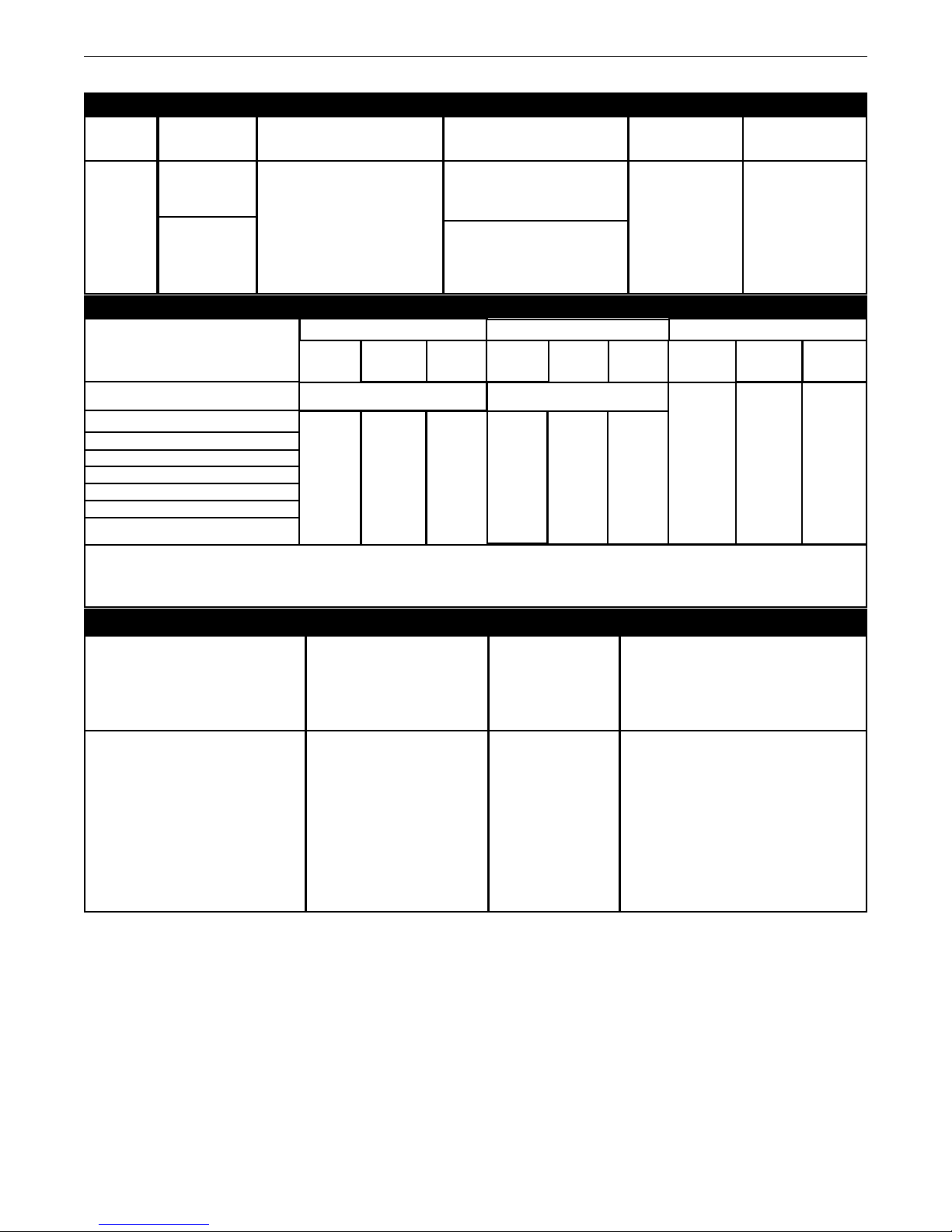
TECHNICAL SPECIFICATIONS - POWER WAVE®S350
POWER SOURCE-INPUT VOLTAGE AND CURRENT
Model
Duty Cycle
nput Voltage ± 10%
I
nput Amperes
I
(1 Phase in parenthesis)
Idle Power
NSTALLATION
I
ower Factor @
P
Rated Output
39/35/19/17/14
*/NA/NA/NA)
(60/67
31/28/15/14/11
300 Watts Max.
(fan on)
.95
K2823-3/
K4188-1
40% rating
100% rating
08/230/400*460/575
2
50/60 Hz
(*includes 380V to 413V)
(60/53/NA/NA/NA)
RATED OUTPUT
INPUT
VOLTAGE/PHASE/
FREQUENCY
40%*
200-208/1/50/60
230/1/50/60
200-208/3/50/60
230/3/50/60
380-415/3/50/60
460/3/50/60
575/3/50/60
350
Amps
31.5
Volts
* On 230 Volt / 1 phase inputs the max. rating is at a duty cycle of 30%, except for GTAW processes.
** For all ra ted singl e ph ase input s, t he o ption al 1 15 V AC dup lex is r ated for 5 A mps when weld ing above
275 Amps at 100% Duty Cycle.
RECOMMENDED INPUT WIRE AND FUSE SIZES
GMAW
60% 60%100%**
300 Amps / 29 Volts
320
Amps
30
300
Amps
29 Volts
Volts
SMAW
40%* 100%
250 Amps / 30 Volts
325
Amps
33 Volts
275
Amps
31
250
Amps
30 Volts
Volts
GTAW-DC
40% 60% 100%**
350 Amps
24 Volts
23Volts
1
325
Amps
300 Amps
22 Volts
INPUT
VOLTAGE / PHASE/
INPUT AMPERE RATING AND
FREQUENCY
200-208/1/50/60
200-208/3/50/60
230/1/50/60
230/3/50/60
380-415/3/50/60
460/3/50/60
575/3/50/60
1. Based on U.S. National electrical Code
2. Also called " inverse time" or "thermal / magnetic" circuit breakers; circuit breakers that have a delay in tripping action that
decreases as the magnitude of the current increases
3. Type SO cord or similar in 30° C ambient
4. When operating on these inputs, the line cord should be changed to an input conductor of 6 AWG or larger.
MAXIMUM
DUTY CYCLE
60A, 100%
39A, 40%
67A, 30%
35A, 40%
19A, 40%
17A, 40%
14A, 40%
CORD SIZE
AWG SIZES (mm2)
6 (13)
8 (10)
4 (16)
8 (10)
12 (4)
12 (4)
14 (2.5)
3
TIME DELAY FUSE
OR BREAKER
2
AMPERAGE
80
50
80
45
30
25
20
A-1
Page 8

OWER WAVE
P
MODEL
®
350 & S350 ALUMINUM
S
ROCESS
P
GMAW
GMAW-Pulse
FCAW
GTAW-DC
SMAW
HEIGHT
WELDING PROCESS
OUTPUT RANGE (AMPERES)
40-350A
5-350A
55-325A
PHYSICAL DIMENSIONS
WIDTH
DEPTH
OCV (Uo)
Mean Peak
40-70V
24V
60V
INSTALLATION
00V
1
WEIGHT
K2823-3/
K4188-1
20.40 in ( 518 mm)
OPERATING TEMPERATURE RANGE
Environmentally Hardened: -4°F to 104°F (-20C to 40C)
IP23 155º(F) Insulation Class
* Weight does not include input cord.
14.00in ( 356 mm)
TEMPERATURE RANGES
Environmentally Hardened: -40°F to 185°F (-40C to 85C)
24.80in ( 630mm)
85 lbs (39 kg)*
STORAGE TEMPERATURE RANGE
Thermal tests have been performed at ambient temperature.
The duty cycle (duty factor) at 40°C has been determined by
simulation.
A-2
Page 9
OWER WAVE
P
®
350 & S350 ALUMINUM
S
INSTALLATION
SAFETY PRECAUTIONS Read this entire installation
ection before you start installation.
s
WARNING
ELECTRIC SHOCK can kill.
• Only qualified personnel should perform
this installation.
• Turn the input power OFF at the
disconnect switch or fuse box before
working on this equipment. Turn off the input power to any
other equipment connected to the welding system at the
disconnect switch or fuse box before working on the
equipment.
• Do not touch electrically hot parts.
• Always connect the POWER WAVE
a proper safety (Earth) ground.
-------------------------------------------------------------
®
S350 grounding lug to
SELECT SUITABLE LOCATION
The POWER WAVE®S350 will operate in harsh
environments. Even so, it is important that simple preventative
measures are followed in order to assure long life and reliable
operation.
• The machine must be located where there is free circulation
of clean air such that air movement in the back, out the sides
and bottom will not be restricted.
STACKING
The POWER WAVE®S350 cannot be stacked.
TILTING
WARNING
• Lift only with equipment of adequate
lifting capacity.
• Be sure machine is stable when lifting.
• Do not operate machine while
suspended when lifting.
FALLING
EQUIPMENT can
cause injury.
-------------------------------------------------------------
Place the machine directly on a secure, level surface or on a recommended
undercarriage. The machine may topple over if this procedure is not
followed.
INPUT AND GROUND CONNECTIONS
Only a qualified electrician should connect the POWER WAVE®S350.
Installation should be made in accordance with the appropriate National
Electrical Code, all local codes and the information in this manual.
• Dirt and dust that can be drawn into the machine should be
kept to a minimum. The use of air filters on the air intake is
not recommended because
normal air flow may be restricted. Failure to observe these
precautions can result in excessive operating temperatures
and nuisance shutdown.
• Keep machine dry. Shelter from rain and snow. Do not place
on wet ground or in puddles.
• Do not mount the POWER WAVE®S350 over combustible surfaces. Where there is a combustible surface directly under
stationary or fixed electrical equipment, that surface shall be
covered with a steel plate at least .060” (1.6mm) thick, which
shall extend not less than 5.90” (150mm) beyond the
equipment on all sides.
LIFTING
Both handles should be used when lifting POWER WAVE®S350. When using
a crane or overhead device a lifting strap should be connected to both
handles. Do not attempt to lift the POWER WAVE®S350 with accessories
attached to it.
MACHINE GROUNDING
The frame of the welder must be grounded. A ground terminal marked with
a ground symbol is located next to the input power connection block.
See your local and national electrical codes for proper
grounding methods.
HIGH FREQUENCY PROTECTION
Locate the POWER WAVE®S350 away from radio controlled machinery. The
normal operation of the POWER WAVE®S350 may adversely affect the
operation of RF controlled equipment, which may result in bodily injury or
damage to the equipment.
A-3
Page 10
OWER WAVE
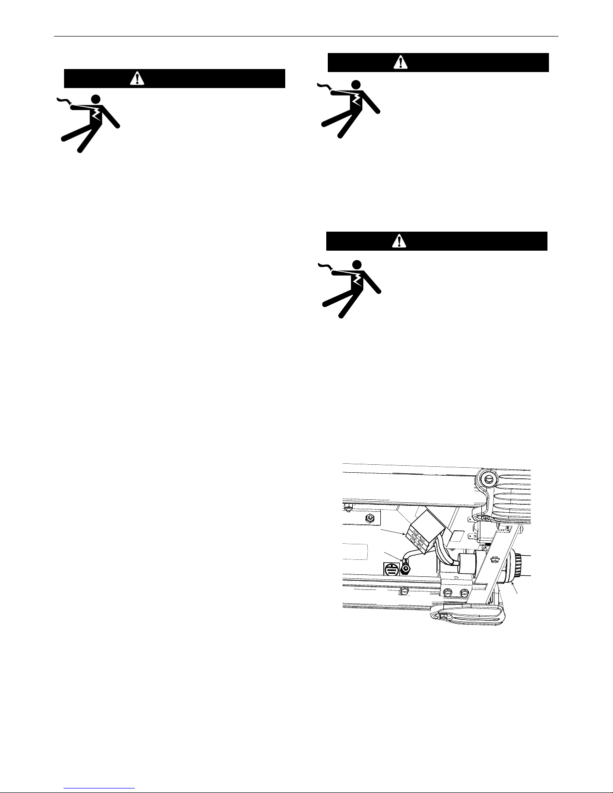
INPUT
POWER
CORD
CONNECTION
BLOCK
GROUND
LUG
P
®
350 & S350 ALUMINUM
S
INPUT CONNECTION
WARNING
Only a qualified electrician should connect
the input leads to the POWER WAVE®S350.
Connections should be made in accordance with all local and national electrical
codes and the connection diagrams.
Failure to do so may result in bodily injury or death.
--------------------------------------------------------------------
A 15 ft. (4.6m) power cord may be provided and wired into the
machine*.
For Single Phase Input
Connect green lead to ground per National Electrical Code.
Connect black and white leads to power.
Wrap red lead with tape to provide 600V insulation.
For Three Phase Input
Connect green lead to ground per National Electric Code.
Connect black, red and white leads to power.
INSTALLATION
WARNING
The POWER WAVE®S350 ON/OFF switch is
ot intended as a service disconnect for
n
this equipment. Only a qualified electrician
should connect the input leads to the
®
POWER WAVE
e made in accordance with all local and
b
S350. Connections should
national electrical codes and the connection diagram located
on the inside of the reconnect access door of the machine.
Failure to do so may result in bodily injury or death.
-------------------------------------------------
POWER CORD REPLACEMENT
WARNING
Only a qualified electrician should connect
the input leads to the POWER WAVE®S350.
Connections should be made in accordance
with all local and national electrical codes
and the connection diagrams. Failure to do
so may result in bodily injury or death.
------------------------------------------------
INPUT FUSE AND SUPPLY WIRE
CONSIDERATIONS
Refer to Specification Section for recommended fuse, wire sizes
and type of the copper wires. Fuse the input circuit with the
recommended super lag fuse or delay type breakers (also called
"inverse time" or "thermal/magnetic" circuit breakers). Choose
input and grounding wire size according to local or national
electrical codes. Using input wire sizes, fuses or circuit breakers
smaller than recommended may result in "nuisance" shut-offs
from welder inrush currents, even if the machine is not being
used at high currents.
INPUT VOLTAGE SELECTION
The POWER WAVE®S350 automatically adjusts to work with different input voltages. No reconnect switches settings are
required.
*An input cord is provided with the POWER WAVE
®
S350.
If the input power cord is damaged or needs to be replaced an
input power connection block is located in the back of the
machine with the access panel removed as shown Figure A.1.
ALWAYS CONNECT THE POWER WAVE GROUNDING LUG
(LOCATED AS SHOWN IN FIGURE A.1) TO A PROPER SAFETY
(EARTH) GROUND.
FIGURE A.1
A-4
Page 11
OWER WAVE
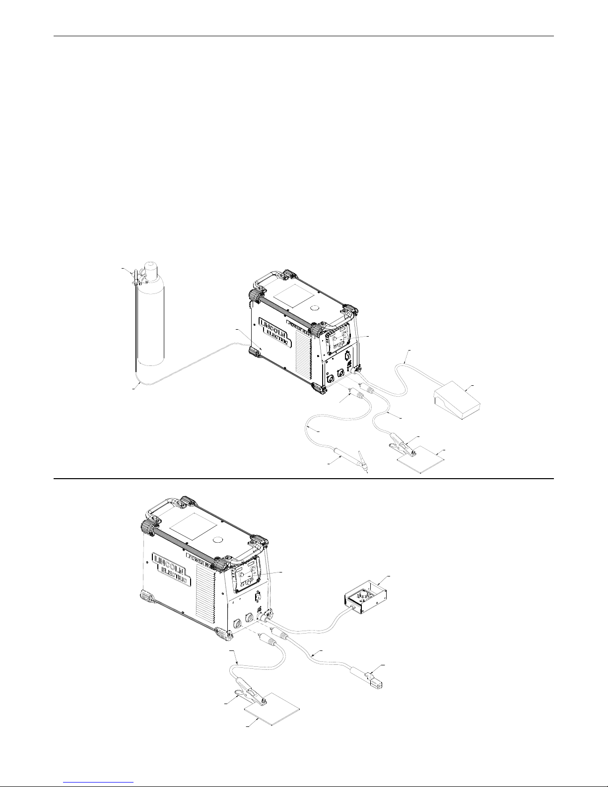
K3001-2
TIG WITH S-SERIES USER INTERFACE
FOOT AMPTROL
W
ORK PIECE
WORK CLAMP
TIG TORCH
K
1782-1,-3,12
TO POSITIVE
(+) STUD
TO REMOTE CONTROL
RECEPTACLE
U
SER INTERFACE
CONTROL PANEL
G
AS SOLENOID KIT
(INSIDE MACHINE)
K
2825-1
TO NEGATIVE
(-) STUD
R
EGULATOR
FLOWMETER
GAS HOSE
KK878 70, K870-2 AND0, K870-2 AND
K2909-1K2909-1
K
960-3
STICK WITH S-SERIES USER INTERFACE
K3001-2
REMOTE CONTROL BOX
K857-2
USER INTERFACE
CONTROL PANEL
T
O POSITIVE
(+) STUD
E
LECTRODE HOLDER KIT
K875 OR K704
(INCLUDES GROUND CLAMP)
TO NEGATIVE
(-) STUD
WORK PIECE
WORK CLAMP
P
®
350 & S350 ALUMINUM
S
INSTALLATION
CONNECTION DIAGRAMS
GTAW (TIG) WELDING
A user interface is required for adjusting the TIG welding settings.
S-series user interface (K3001-2) can be installed into the power
source (Figure A.2). Refer to the connection diagrams based on
the user interface that is being used. Alternate configurations are
possible depending on the wire feeder that is being used. Refer to
the wire feeder’s manual for alternative configurations.
FIGURE A.2
SMAW (STICK) WELDING
Similar to TIG welding a user interface is required for adjusting
he Stick welding settings. A Power Feed wire feeder can be
t
used as the user interface, or a K3001-2 (user interface control
panel) can be installed into the power source (Figure A.3). The
connection diagram shown is based on the S-Series user
nterface (K3001-2). In this diagram the remote control box is
i
optional.
GMAW (MIG) WELDING
An arclink compatible wire feeder is recommended for Mig
welding. Refer to Figure A.4 for the connection details.
FIGURE A.3
A-5
Page 12
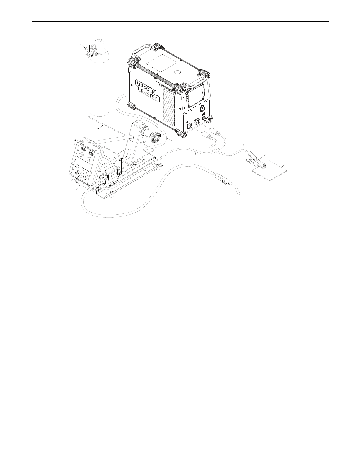
OWER WAVE
MIG PROCESS
REGULATOR
FLOWMETER
GAS HOSE
WORK PIECE
WORK CLAMP
TO POSITIVE
(+) STUD
TO NEGATIVE (-) STUD
PF10-M
WIRE FEEDER
ARCLINK CABLE
K
1543-[XX]
P
®
350 & S350 ALUMINUM
S
INSTALLATION
FIGURE A.4
A-6
Page 13
OWER WAVE
P
®
350 & S350 ALUMINUM
S
RECOMMENDED WORK CABLE SIZES FOR
ARC WELDING
Connect the electrode and work cables between the appropriate
output studs of the Power Wave S350 per the following
guidelines:
Most welding applications run with the electrode being positive
•
(+). For those applications, connect the electrode cable
between the wire drive feed plate and the positive (+) output
stud on the power source. Connect a work lead from the
negative (-) power source output stud to the work piece
• When negative electrode polarity is required, such as in some
Innershield applications, reverse the output connections at the
power source (electrode cable to the negative (-) stud, and
work cable to the positive (+) stud).
CAUTION
Negative electrode polarity operation WITHOUT use of a
remote work sense lead (21) requires the Negative Electrode
Polarity attribute to be set. See the Remote Sense Lead
Specification section of this document for further details.
--------------------------------------------------------------------
For additional Safety information regarding the electrode and
work cable set-up, See the standard “SAFETY INFORMATION”
located in the front of this Instruction Manual.
General Guidelines
INSTALLATION
Select the appropriate size cables per the “Output Cable
•
Guidelines” below. Excessive voltage drops caused by
undersized welding cables and poor connections often result in
unsatisfactory welding performance. Always use the largest
welding cables (electrode and work) that are practical, and be
sure all connections are clean and tight.
Note: Excessive heat in the weld circuit indicates undersized
cables and/or bad connections.
• Route all cables directly to the work and wire feeder,
avoid excessive lengths and do not coil excess cable.
Route the electrode and work cables in close proximity to one
another to minimize the loop area and therefore the inductance
of the weld circuit.
• Always weld in a direction away from the work (ground)
connection.
Table A.1 shows copper cable sizes recommended for different
currents and duty cycles. Lengths stipulated are the distance
from the welder to work and back to the welder again. Cable
sizes are increased for greater lengths primarily for the purpose
of minimizing cable drop.
OUTPUT CABLE GUIDELINES (Table A.1)
Percent Duty
Amperes
200
200
250
250
250
250
300
300
350
** Tabled values are for operation at ambient temperatures of 104°F (40°C) and below. Applications above 104°F (40°C) may require cables larger
than recommended, or cables rated higher than 167°F (75°C).
Cycle
60
100
30
40
60
100
60
100
40
CABLE SIZES FOR COMBINED LENGTHS OF ELECTRODE AND WORK CABLES [RUBBER COVERED
COPPER - RATED 167°F (75°C)]**
0 to 50 Ft.
2
2
3
2
1
1
1
2/0
1/0
50 to 100 Ft.
2
2
3
2
1
1
1
2/0
1/0
100 to 150 Ft.
2
2
2
1
1
1
1
2/0
2/0
150 to 200 Ft.
1
1
1
1
1
1
1/0
2/0
2/0
200 to 250 Ft.
1/0
1/0
1/0
1/0
1/0
1/0
2/0
3/0
3/0
A-7
Page 14
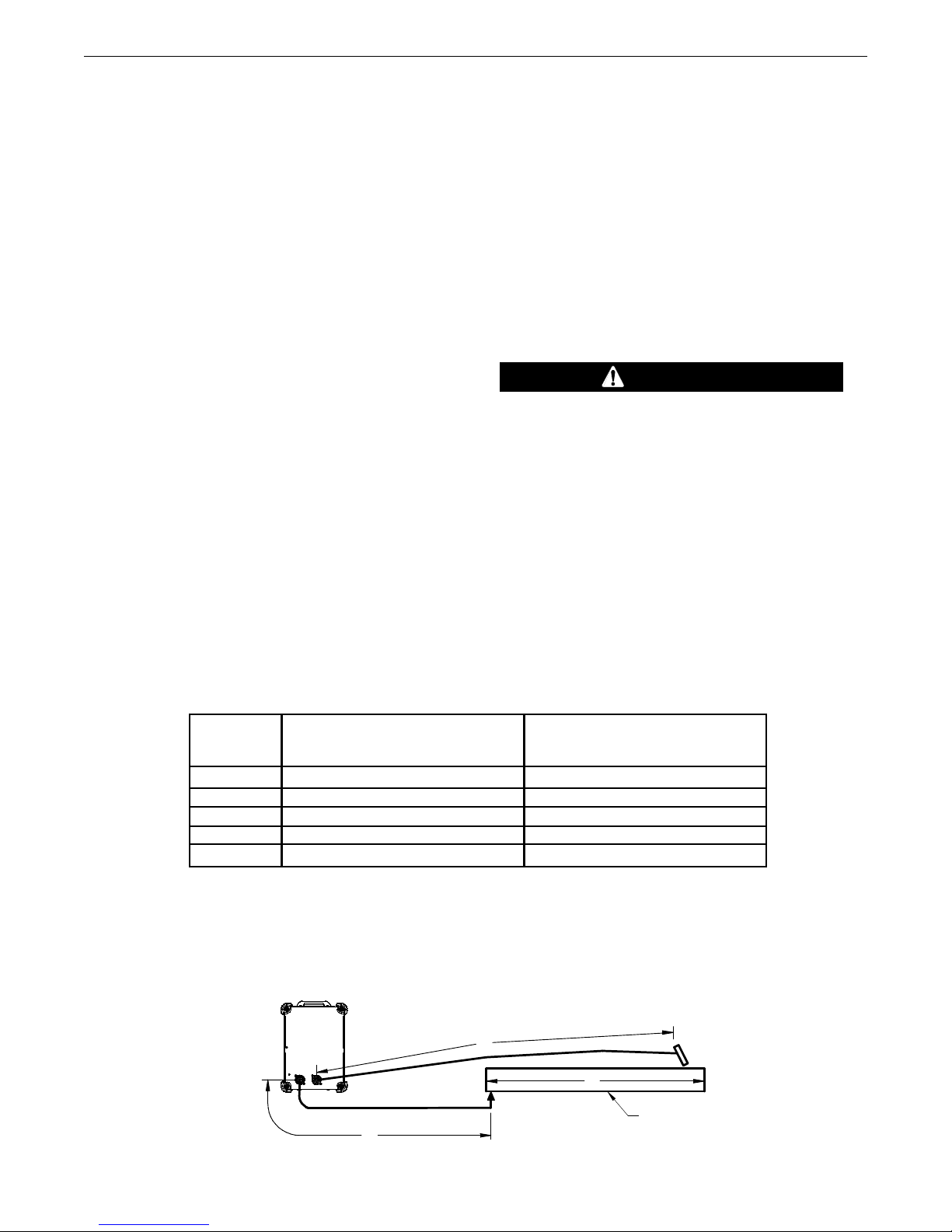
B
A
C
WORK
POWER
WAVE
S350
OWER WAVE
P
®
350 & S350 ALUMINUM
S
INSTALLATION
CABLE INDUCTANCE AND ITS EFFECTS ON
WELDING
Excessive cable inductance will cause the welding performance
to degrade. There are several factors that contribute to the
verall inductance of the cabling system including cable size,
o
and loop area. The loop area is defined by the separation distance between the electrode and work cables, and the overall
welding loop length. The welding loop length is defined as the
total of length of the electrode cable (A) + work cable (B) + work
path (C) (See Figure A.5).
To minimize inductance always use the appropriate size cables,
and whenever possible, run the electrode and work cables in
close proximity to one another to minimize the loop area. Since
the most significant factor in cable inductance is the welding
loop length, avoid excessive lengths and do not coil excess
cable. For long work piece lengths, a sliding ground should be
considered to keep the total welding loop length as short as
possible.
REMOTE SENSE LEAD
SPECIFICATIONS
Remote voltage sense leads are used to improve the accuracy of
he arc voltage information supplied to the control pc board.
t
Sense Lead Kits (K940-xx) are available for this purpose.
®
The Power Wave
S350 has the ability to automatically sense
when remote sense leads are connected. With this feature there
re no requirements for setting-up the machine to use remote
a
sense leads. This feature can be disabled through the Weld
Manager Utility (available at www.powerwavesoftware.com) or
through the set up menu (if a user interface is installed into the
power source).
If the auto sense lead feature is disabled and remote voltage
sensing is enabled but the sense leads are missing, improperly
connected extremely high welding outputs may occur.
--------------------------------------------------------------------
CAUTION
General Guidelines for Voltage Sense Leads
Sense leads should be attached as close to the weld as practical,
and out of the weld current path when possible. In extremely
sensitive applications it may be necessary to route cables that
contain the sense leads away from the electrode and work
welding cables.
Voltage Sensing Overview
Voltage sense leads requirements are based on the weld process
(See Table A.2)
The best arc performance occurs when the Power Wave®S350
has accurate data about the arc conditions.
Depending upon the process, inductance within the electrode
and work cables can influence the voltage apparent at the studs
of the welder, and have a dramatic effect on performance.
TABLE A.2
Process
Electrode Voltage Sensing
67 lead
GMAW
GMAW-P
FCAW
GTAW
SMAW
(1)
The electrode voltage sense lead (67) is automatically enabled by the weld process, and integral to the 5 pin arclink control cable (K1543-xx).
(2)
When a work voltage sense lead (21) is connected the power source will automatically switch over to using this feedback (if the auto sense feature is enable).
(3)
Negative polarity semi-automatic process operation WITHOUT use of a remote work sense lead (21) requires the Negative Electrode Polarity attribute to be set.
67 lead required
67 lead required
67 lead required
Voltage sense at studs
Voltage sense at studs
(1)
Work Voltage Sensing
21 lead
21 lead optional
21 lead optional
21 lead optional
Voltage sense at studs
Voltage sense at studs
(2)
(3)
(3)
(3)
FIGURE A.5
A-8
Page 15

OWER WAVE
P
®
350 & S350 ALUMINUM
S
Electrode Voltage Sensing
The remote ELECTRODE sense lead (67) is built into the 5-pin
rclink control cable and is always connected to the wire drive
a
feed plate when a wire feeder is present. Enabling or disabling
lectrode voltage sensing is application specific, and
e
automatically configured by the active weld mode.
Work Voltage Sensing
While most applications perform adequately by sensing the work
voltage directly at the output stud, the use of a remote work
voltage sense lead is recommended for optimal performance.
The remote WORK sense lead (21) can be accessed through the
four-pin voltage sense connector located on the control panel by
using the K940 Sense Lead Kit. It must be attached to the work
as close to the weld as practical, but out of the weld current
path. For more information regarding the placement of remote
work voltage sense leads, see in this section entitled "Voltage
Sensing Considerations for Multiple Arc Systems."
INSTALLATION
Negative Electrode Polarity
®
The Power Wave
S350 has the ability to automatically sense the
polarity of the sense leads. With this feature there are no set-up
requirements for welding with negative electrode polarity. This
feature can be disabled through the Weld Manager Utility
(available at www.powerwavesoftware.com) or through the set
up menu (if a user interface is installed into the power source).
If the auto sense lead feature is disabled and the weld
polarity attribute is improperly configured extremely high
welding outputs may occur.
--------------------------------------------------------------------
CAUTION
While most applications perform adequately by sensing the work
voltage directly at the output stud, the use of a remote work
voltage sense lead is recommended for optimal performance.
The remote WORK sense lead (21) can be accessed through the
four-pin voltage sense connector located on the control panel by
using the K940 Sense Lead Kit. It must be attached to the work
as close to the weld as practical, but out of the weld current
path. For more information regarding the placement of remote
work voltage sense leads, see the section entitled "Voltage
Sensing Considerations for Multiple Arc Systems."
A-9
Page 16
Direction
of Travel
Connect all
Work Leads at
the Beginning
of the Weld
Connect all Sense
Leads at the End
of the Weld
OWER WAVE
P
®
350 & S350 ALUMINUM
S
INSTALLATION
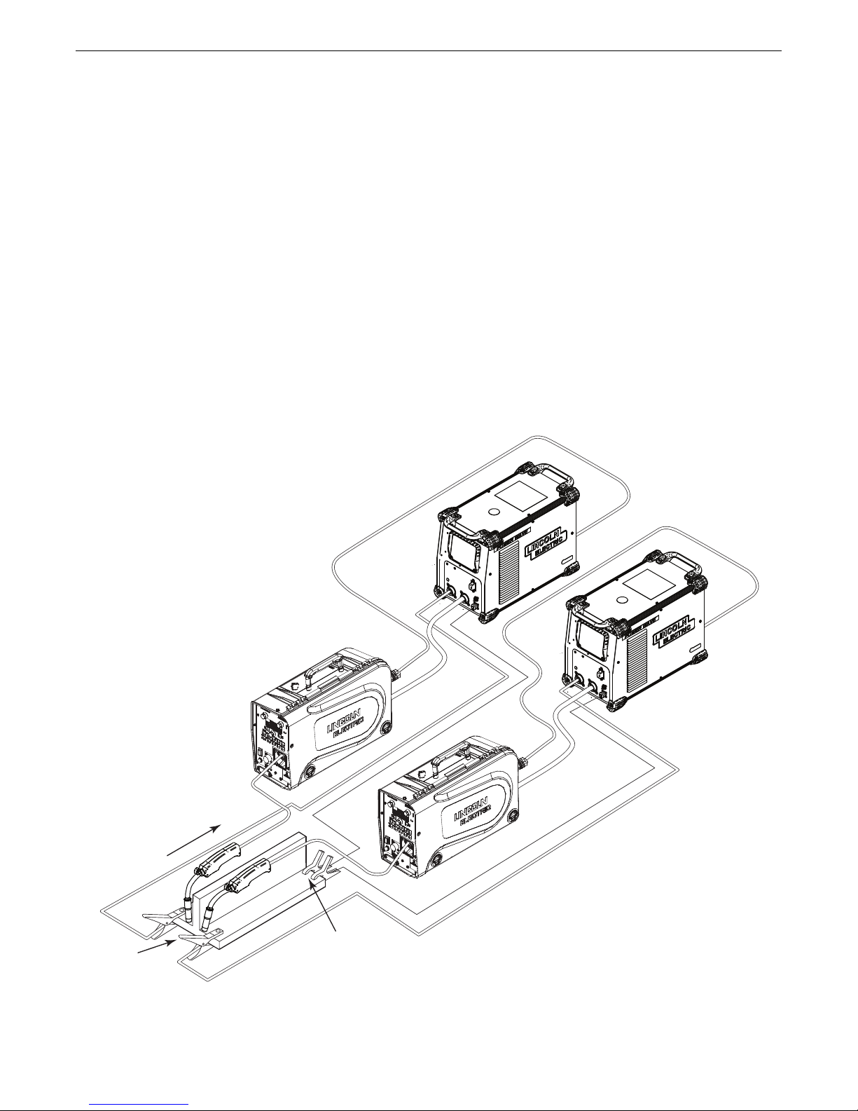
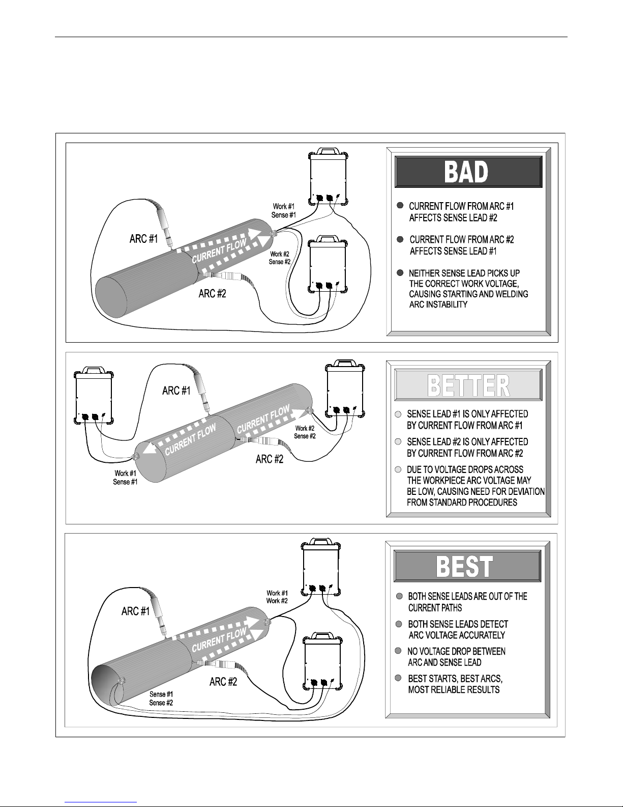
VOLTAGE SENSING CONSIDERATIONS FOR
MULTIPLE ARC SYSTEMS
Special care must be taken when more than one arc is welding
simultaneously on a single part. Multiple arc applications do not
necessarily dictate the use of remote work voltage sense leads,
ut they are strongly recommended.
b
If Sense Leads ARE NOT Used:
• Avoid common current paths. Current from adjacent arcs can
induce voltage into each others current paths that can be
misinterpreted by the power sources, and result in arc
interference.
If Sense Leads ARE Used:
(See Figure A.6)
FIGURE A.6
• Position the sense leads out of the path of the weld current.
Especially any current paths common to adjacent arcs.
Current from adjacent arcs can induce voltage into each
thers current paths that can be misinterpreted by the power
o
sources, and result in arc interference.
• For longitudinal applications, connect all work leads at one
end of the weldment, and all of the work voltage sense leads
at the opposite end of the weldment. Perform welding in the
direction away from the work leads and toward the sense
leads.
A-10
Page 17
OWER WAVE
P
O
W
ER
SOURCE
#2
POWER
SOURCE
#1
POWER
PO
WER
SOURCE
SOURCE
#1
PO
WER
SOURCE
#2
#2
POWER
SOURCE
#1
P
®
350 & S350 ALUMINUM
S
INSTALLATION
• For circumferential applications, connect all work leads on
one side of the weld joint, and all of the work voltage sense
leads on the opposite side, such that they are out of the
current path.
(See Figure A.7)
IGURE A.7
F
A-11
Page 18

OWER WAVE
P
®
350 & S350 ALUMINUM
S
CONTROL CABLE CONNECTIONS
General Guidelines
Genuine Lincoln control cables should be used at all times
(except where noted otherwise). Lincoln cables are specifically
designed for the communication and power needs of the Power
Wave®/ Power Feed™systems. Most are designed to be
connected end to end for ease of extension. Generally, it is
recommended that the total length not exceed 100ft. (30.5m).
The use of non-standard cables, especially in lengths greater
than 25 feet, can lead to communication problems (system
shutdowns), poor motor acceleration (poor arc starting), and low
wire driving force (wire feeding problems). Always use the
shortest length of control cable possible, and DO NOT coil
excess cable.
Regarding cable placement, best results will be obtained when
control cables are routed separate from the weld cables. This
minimizes the possibility of interference between the high
currents flowing through the weld cables, and the low level
signals in the control cables. These recommendations apply to
all communication cables including ArcLink®and Ethernet
connections.
INSTALLATION
Product specific Installation Instructions
Connection Between Power Source and ArcLink®Compatible
Wirefeeders (K1543, K2683 – ArcLink Control Cable)
The 5-pin ArcLink control cable connects the power source to
the wire feeder. The control cable consists of two power leads,
one twisted pair for digital communication, and one lead for
voltage sensing. The 5-pin ArcLink connection on the Power
Wave S350 is located on the rear panel above the power cord.
The control cable is keyed and polarized to prevent improper
connection. Best results will be obtained when control cables are
routed separate from the weld cables, especially in long distance
applications. The recommended combined length of the ArcLink
control cable network should not exceed 200ft. (61.0m).
Connection Between Power Source and Ethernet Networks
®
The Power Wave
S350 is equipped with an IP67 rated ODVA
compliant RJ-45 Ethernet connector, which is located on the rear
panel. All external Ethernet equipment (cables, switches, etc.),
as defined by the connection diagrams, must be supplied by the
customer. It is critical that all Ethernet cables external to either a
conduit or an enclosure are solid conductor, shielded cat 5e
cable, with a drain. The drain should be grounded at the source
of transmission. For best results, route Ethernet cables away
from weld cables, wire drive control cables, or any other current
carrying device that can create a fluctuating magnetic field. For
additional guidelines refer to ISO/IEC 11801. Failure to follow
these recommendations can result in an Ethernet connection
failure during welding.
A-12
Page 19

NOTES
A-13
Page 20

OWER WAVE
P
®
350 & S350 ALUMINUM
S
PERATION
O
SAFETY PRECAUTIONS
READ AND UNDERSTAND ENTIRE SECTION BEFORE OPERATING
MACHINE.
WARNING
• ELECTRIC SHOCK CAN KILL.
• Do not touch electrically live part or
lectrode with skin or wet clothing.
e
• Insul ate your self from wor k a nd
ground.
• Always wear dry insulating gloves.
• Do not operate with covers, panels or guards removed
or open.
------------------------------------------------------------------
• FUMES AND GASSES can be dangerous.
• Keep your head out of fumes.
• Use ventilation or exhaust to remove
fumes from breathing zone.
----------------------------------------------
• WELDING SPARKS can cause fire or
explosion.
• Keep flammable material away.
GRA PHIC SYM BOLS THAT APP EAR ON TH IS
MACHINE OR IN THIS MANUAL
WARNING OR
CAUTION
DANGEROUS
VOLTAGE
POSITIVE OUTPUT
NEGATIVE OUTPUT
HIGH TEMPERATURE
STATUS
----------------------------------------------
ARC RAYS can burn.
• Wear eye, ear and body protection.
------------------------------------------------------------------
SEE ADDITIONAL WARNING INFORMATION UNDER ARC
WELDING SAFETY PRECAUTIONS AND IN THE FRONT OF
THIS OPERATING MANUAL.
------------------------------------------------------------------
POWER-UP SEQUENCE
When the POWER WAVE®S350 is powered up, it can take as
long as 30 seconds for the machine to be ready to weld. During
this time period the user interface will not be active.
DUTY CYCLE
The duty cycle is based on a ten-minute period. A 40% duty
cycle represents 4 minutes of welding and 6 minutes of idling in
a ten-minute period. Refer to the technical specification section
for the Power Wave S350’s duty cycle ratings.
PROTECTIVE GROUND
COOLER
OUTPUT
OPERATORS
MANUAL
WORK
CIRCUIT BREAKER
B-1
Page 21

OWER WAVE
P
®
350 & S350 ALUMINUM
S
OPERATION
PRODUCT DESCRIPTION
PRODUCT SUMMARY
he Power Wave
T
source with high-end functionality capable of Stick, DC TIG, MIG,
ulsed MIG and Flux-Cored welding. It is ideal for a wide variety
P
of materials including aluminum, stainless, and nickel — where
arc performance is critical.
The Power Wave
system. Like existing Power Wave’s®, the software based architecture allows for future upgradeability. One significant change
from the current range of Power Wave®units is that the Ethernet
communication feature is standard on the Power Wave®S350
which allows for effortless software upgrades through
Powerwavesoftware.com. The Ethernet communication also
gives the Power Wave®S350 the ability to run Production
Monitoring™ 2. Also a Devicenet option which will allow the
Power Wave®S350 to be used in a wide range of configurations.
Also, the Power Wave®S350 is being designed to be compatible
with future advanced welding modules like STT
®
350 is a portable multi-process power
S
®
S350 is designed to be a very flexible welding
RECOMMENDED PROCESSES AND
EQUIPMENT
EQUIPMENT LIMITATIONS
Only ArcLink compatible semiautomatic wire feeders and users
nterfaces may be used. If other Lincoln wire feeders or
i
non-Lincoln wire feeders are used there will be limited process
capability and performance and features will be limited.
The Power Wave®S350 is recommended for semiautomatic welding,
and may also be suitable for basic hard automation applications. The
Power Wave®S350 can be set up in a number of configurations, some
requiring optional equipment or welding programs.
RECOMMENDED EQUIPMENT
The Power Wave®S350 is designed to be compatible with the
current range of Power Feed™ systems including future
versions of ArcLink®feeders.
RECOMMENDED PROCESSES
The Power Wave S350 is a high speed, multi-process power
source capable of regulating the current, voltage, or power of the
welding arc. With an output range of 5 to 350 amperes, it
supports a number of standard processes including synergic
GMAW, GMAW-P, FCAW, FCAW-SS, SMAW, GTAW and GTAW-P
on various materials especially steel, aluminum and stainless.
PROCESS LIMITATIONS
The software based weld tables of the Power Wave®S350 limit
the process capability within the output range and the safe limits
of the machine. In general the processes will be limited to
.030-.052 solid steel wire, .030 -.045 stainless wire, .035 -1/16
cored wire, and .035 - 1/16 Aluminum wire.
B-2
Page 22

OWER WAVE
1
2
3
4
6
5
7
8
P
®
350 & S350 ALUMINUM
S
OPERATION
DESIGN FEATURES
oaded with Standard Features
L
• Multiple process DC output range: 5 - 350 Amps
200 – 600 VAC, 1/3 phase, 50-60Hz input power
•
• New and Improved Line Voltage Compensation holds the
output constant over wide input voltage fluctuations.
• Utilizes next generation microprocessor control, based on the
• State of the art power electronics technology yields superior
• Electronic over current protection
• Input over voltage protection.
• F.A.N. (fan as needed). Cooling fan only runs when needed.
• Thermostatically protected for safety and reliability.
®
ArcLink
platform.
welding capability.
CASE FRONT CONTROLS
(See Figure B.1)
1. USER INTERFACE (optional)
2. STATUS LED - (See Troubleshooting Section for operational
functions)
3. THERMAL LED - Indicates when machine has thermal fault.
4. POWER SWITCH - Controls power to the Power Wave®S350.
5. NEGATIVE WELD OUTPUT
6. POSITIVE WELD OUTPUT
7. WORK SENSE LEAD CONNECTOR
8. 12-PIN CONNECTOR (Optional)
• Ethernet connectivity.
FIGURE B.1
• Panel mounted Status and Thermal LED indicators facilitate
quick and easy troubleshooting.
• Potted PC boards for enhanced ruggedness/reliability.
• Enclosure reinforced with heavy duty aluminum extrusions for
mechanical toughness
• Waveform Control Technology™ for good weld appearance
and low spatter, even when welding nickel alloys.
• Sync Tandem installed.
• Cam-Lock type connectors
B-3
Page 23

OWER WAVE
66
88
11
22
33
44
55
77
11
22
33
44
55
66
77
88
P
®
350 & S350 ALUMINUM
S
OPERATION
CASE BACK CONTROLS
(See Figure B.2 for Code 11694)
1. 115 VAC KIT (OPTIONAL)
2. ARCLINK CONNECTOR
3. CIRCUIT BREAKER
4. SYNC TANDEM/ STT CONNECTOR
5. DEVICENET KIT (OPTIONAL)
6. ETHERNET
7. RESERVED FOR FUTURE DEVELOPMENT
8. GAS SOLENOID KIT (OPTIONAL)
CASE BACK CONTROLS
(See Figure B.2a for Code 11782/12371)
1. 115 VAC KIT (OPTIONAL)
(STANDARD ON K4188-1)
2. ARCLINK CONNECTOR
3. CIRCUIT BREAKER
4. SYNC TANDEM/ STT CONNECTOR
5. DEVICENET KIT (OPTIONAL)
6. ETHERNET
7. RESERVED FOR FUTURE DEVELOPMENT
8. GAS SOLENOID KIT (OPTIONAL)
FIGURE B.2
FIGURE B.2a
B-4
Page 24

OWER WAVE
P
®
350 & S350 ALUMINUM
S
OPERATION
COMMON WELDING PROCEDURES
WARNING
MAKING A WELD
he serviceability of a product or structure utilizing the
T
welding programs is and must be the sole responsibility of
the builder/user. Many variables beyond the control of The
Lincoln Electric Company affect the results obtained in
applying these programs. These variables include, but are
not limited to, welding procedure, plate chemistry and
temperature, weldment design, fabrication methods and
service requirements. The available range of a welding
program may not be suitable for all applications, and the
build/user is and must be solely responsible for welding
program selection.
Choose the electrode material, electrode size, shielding gas, and
process (GMAW, GMAW-P etc.) appropriate for the material to be
welded.
Select the weld mode that best matches the desired welding
process. The standard weld set shipped with the Power Wave
S350 encompasses a wide range of common processes that will
meet most needs. If a special weld mode is desired, contact the
local Lincoln Electric sales representative.
All adjustments are made through the user interface. Because of
the different configuration options your system may not have all
of the following adjustments.
See Accessories Section for Kits and Options avaliable to use
with the Power Wave®S350.
®
Basic Welding Controls
Weld Mode
Selecting a weld mode determines the output characteristics of
the Power Wave®power source. Weld modes are developed
with a specific electrode material, electrode size, and shielding
gas. For a more complete description of the weld modes
rogrammed into the Power Wave
p
®
350 at the factory, refer to
S
the Weld Set Reference Guide supplied with the machine or
available at www.powerwavesoftware.com.
Wire Feed Speed (WFS)
In synergic welding modes (synergic CV, GMAW-P), WFS is the
dominant control parameter. The user adjusts WFS according to
factors such as wire size, penetration requirements, heat input,
etc. The Power Wave
®
S350 then uses the WFS setting to adjust
the voltage and current according to settings contained in the
Power Wave.
In non-synergic modes, the WFS control behaves like a
conventional power source where WFS and voltage are
independent adjustments. Therefore, to maintain proper arc
characteristics, the operator must adjust the voltage to
compensate for any changes made to the WFS.
Amps
In constant current modes, this control adjusts the welding
amperage.
Volts
In constant voltage modes, this control adjusts the welding
voltage.
Definition of Welding Modes
NON-SYNERGIC WELDING MODES
• A Non-synergic welding mode requires all welding process
variables to be set by the operator.
SYNERGIC WELDING MODES
• A Synergic welding mode offers the simplicity of single knob
control. The machine will select the correct voltage and
amperage based on the Wire Feed Speed (WFS) set by the
operator.
Trim
In pulse synergic welding modes, the Trim setting adjusts the arc
length. Trim is adjustable from 0.50 to 1.50. 1.00 is the
nominal setting and is a good starting point for most conditions.
UltimArc™ Control
UltimArc™ Control allows the operator to vary the arc
characteristics. UltimArc™ Control is adjustable from –10.0 to
+10.0 with a nominal setting of 0.0.
B-5
Page 25

OWER WAVE
P
MAW (STICK) WELDING
S
®
350 & S350 ALUMINUM
S
The welding current and Arc Force settings can be set through a
ower Feed
P
™
0M or Power Feed
1
™
5M wire feeder.
2
Alternatively an optional Stick / TIG UI can be installed into the
power source to control these settings locally.
n a SMAW (STICK mode), Arc Force can be adjusted. It can be
I
set to the lower range for a soft and less penetrating arc characteristic (negative numeric values) or to the higher range (positive
numeric values) for a crisp and more penetrating arc. Normally,
when welding with cellulosic types of electrodes (E6010, E7010,
E6011), a higher energy arc is required to maintain arc stability.
This is usually indicated when the electrode sticks to the workpiece or when the arc becomes unstable during manipulative
technique. For low hydrogen types of electrodes (E7018, E8018,
E9018, etc.) a softer arc is usually desirable and the lower end of
the Arc Control suits these types of electrodes. In either case the
arc control is available to increase or decrease the energy level
delivered to the arc.
GTAW (TIG) WELDING
The welding current can be set through a Power Feed 10M or
Power Feed
™
25M wire feeder. Alternatively an optional Stick /
TIG UI can be installed into the power source to control these
settings locally.
OPERATION
CONSTANT VOLTAGE WELDING
ynergic CV
S
For each wire feed speed, a corresponding voltage is
preprogrammed into the machine through special software at the
factory.
The nominal preprogrammed voltage is the best average voltage
or a given wire feed speed, but may be adjusted to preference.
f
When the wire feed speed changes, the Power Wave
®
S350
automatically adjusts the voltage level correspondingly to
maintain similar arc characteristics throughout the WFS range.
Non Synergic CV
In non-synergic modes, the WFS control behaves more like a
conventional CV power source where WFS and voltage are
independent adjustments. Therefore to maintain the arc
characteristics, the operator must adjust the voltage to
compensate for any changes made to the WFS.
All CV Modes
Pinch adjusts the apparent inductance of the wave shape. The
“pinch” function is inversely proportional to inductance.
Therefore, increasing Pinch Control greater than 0.0 results in a
crisper arc (more spatter) while decreasing the Pinch Control to
less than 0.0 provides a softer arc (less spatter).
The TIG mode features continuous control from 5 to 350 amps
with the use of an optional foot amptrol. The Power Wave®S350
can be run in either a Touch Start TIG mode or Scratch start TIG
mode.
PULSE WELDING
Pulse welding procedures are set by controlling an overall “arc
length” variable. When pulse welding, the arc voltage is highly
dependent upon the waveform. The peak current, back ground
current, rise time, fall time and pulse frequency all affect the
voltage. The exact voltage for a given wire feed speed can only
be predicted when all the pulsing waveform parameters are
known. Using a preset voltage becomes impractical and instead
the arc length is set by adjusting “trim”.
Trim adjusts the arc length and ranges from 0.50 to 1.50 with a
nominal value of 1.00. Trim values greater than 1.00 increase
the arc length, while values less than 1.00 decrease the arc
length. (See Figure B.3)
FIGURE B.3
B-6
Page 26

OWER WAVE
P
®
350 & S350 ALUMINUM
S
OPERATION
Most pulse welding programs are synergic. As the wire feed
peed is adjusted, the Power Wave
s
®
350 will automatically
S
recalculate the waveform parameters to maintain similar arc
properties.
The Power Wave
®
S350 utilizes “adaptive control” to
compensate for changes in the electrical stick-out while welding.
(Electrical stick-out is the distance from the contact tip to the
ork piece.) The Power Wave
w
®
350 waveforms are optimized
S
for a 0.75” stick-out. The adaptive behavior supports a range of
stick-outs from 0.50 to 1.25”. At very low or high wire feed
speeds, the adaptive range may be less due to reaching physical
limitations of the welding process.
UltimArc™ Control adjusts the focus or shape of the arc.
UltimArc™ Control is adjustable from -10.0 to +10.0 with a
nominal setting of 0.0. Increasing the UltimArc™ Control
increases the pulse frequency and background current while
decreasing the peak current. This results in a tight, stiff arc
used for high speed sheet metal welding. Decreasing the
UltimArc™ Control decreases the pulse frequency and
background current while increasing the peak current. This
results in a soft arc good for out of position welding.
(See Figure B.4)
FIGURE B.4
B-7
Page 27

OWER WAVE
P
®
350 & S350 ALUMINUM
S
CCESSORIES
A
KITS, OPTIONS AND ACCESSORIES
All Kits Options and Accessories are found on the Web site:
(www.lincolnelectric.com)
FACTORY INSTALLED
None Available
FIELD INSTALLED OPTIONS
GENERAL OPTIONS
Stick / Tig User Interface Kit
Mounts inside the front panel of the Power Wave®S350. Allows
stick and Tig operation without having a wire feeder.
Order K3001-2
115 VAC Auxiliary Power Kit
Mounts inside the back of the Power Wave®S350. Adds 115 VAC
/ 60 Hz auxiliary power capability to the Power Wave S350
(compatible with the K2823-1 and K2823-3 power source)
Order K2829-1
DeviceNet Kit
Mounts inside the back of the Power Wave®S350. Allows
Devicenet objects to communicate with the Power Wave S350.
Order K2827-1
Work Voltage Sense Lead Kit
Required to accurately monitor voltage at the arc.
Order K940-XX Series
Order K1811-XX Series
Coaxial Welding Cable
Optimum weld cables for minimizing cable inductance and
ptimizing welding performance.
o
AWG 1/0 Coaxial Cables:
Order K1796-25 for 25 feet (7.6 m) cable length.
rder K1796-50 for 50 feet (15.2 m) cable length.
O
Order K1796-75 for 75 feet (22.9 m) cable length.
Order K1796-100 for 100 feet (30.5 m) cable length.
AWG #1 Coaxial Cables:
Order K2593-25 for 25 feet (7.6 m) cable length.
Order K2593-50 for 50 feet (15.2 m) cable length.
Order K2593-100 for 100 feet (30.5 m) cable length.
K2909-1
12-pin to 6-pin adapter.
K2910-1
12-pin to 7-pin adapter.
Welding Fume Extractors
Lincoln offers a wide range of fume extraction environmental
system solutions, ranging from portable systems easily wheeled
around a shop to shop-wide central systems servicing many
dedicated welding stations.
Request Lincoln publication E13.40
(See www.lincolnelectric.com)
Deluxe Adjustable Gas Regulator & Hose Kit
Accommodates CO2, Argon, or Argon-blend gas cylinders.
Includes a cylinder pressure gauge, dual scale flow gauge and
4.3 ft. (1.3 m) gas hose.
Order K586-1
Work and Wire Feeder 2/0 Weld Cable Package
Includes Cam-Lock connectors, work clamps, 15 ft. (4.5 m) work
cable and 10 ft. (3.0 m) electrode cable. Rated 350 amps, 60%
duty cycle.
Order K1803-2
2
Cam-Lock cable plug for 2/0 (50mm
) cable. Order K2946-1
C-1
Page 28

OWER WAVE
P
®
350 & S350 ALUMINUM
S
ACCESSORIES
STICK OPTIONS
ACCESSORY KIT - 150 Amp
For stick welding. Includes 20 ft. (6.1m)
#6 electrode cable with lug, 15 ft. (4.6m)
#6 work cable with lugs, headshield, filter
plate, work clamp, electrode holder and
ample pack of mild steel electrode. For
s
use with K2946-1.
ORDER K875
ACCESSORY KIT - 400 AMP
For stick welding. Includes 35 ft. (10.7m)
2/0 electrode cable with lug, 30 ft. (9.1m)
2/0 work cable with lugs, headshield, filter
plate, work clamp and electrode holder.
For use with K2946-1.
ORDER K704
REMOTE OUTPUT CONTROL
Permits remote adjustment of output.
Order K857-2 for 25 ft (7.6m) with 12 pin
connector.
TIG-Mate™ 17V Air-Cooled TIG Torch Starter Pack
Get everything you need for TIG welding in one complete
easy-to-order kit packaged in its own portable carrying case.
Includes: PTA-17V torch, parts kit, Harris®flowmeter/regulator,
10 ft.
(3.0 m) gas hose, and work clamp and cable.
Order K2265-1
MIG OPTIONS
Work and Feeder Welding Cables
350 amps, 60% duty cycle with Cam-Lock connectors and
Ground Clamp.
Order K1803-2
COMPATIBLE LINCOLN EQUIPMENT
Any Arclink compatible wire feeding equipment
(See www.lincolnelectric.com)
TIG OPTIONS
Pro-Torch™ TIG Torches
A full line of air-cooled and water-cooled torches available.
Request Lincoln publication E12.150
(See www.lincolnelectric.com)
Hand Amptrol
Provides 25 ft. (7.6 m) of remote current
control for TIG welding.
Order K963-4 for Hand Amptrol with 12 pin
connector
Foot Amptrol
Provides 25 ft. (7.6 m) of remote current
control for TIG welding. Order K870-2 for
Foot Amptrol with 12 pin connector.
Cam-Lock Torch Adapter
For connecting K1782-1, K1782-3, K1782-12 torches to the
S350.
Order K960-3
®
®
C-2
Page 29

OWER WAVE
P
®
350 & S350 ALUMINUM
S
SAFETY PRECAUTIONS
WARNING
ELECTRIC SHOCK can kill.
•Do not operate with covers removed.
•Turn off power source before installing or
ervicing.
s
•Do not touch electrically hot parts.
• Turn the input power to the welding
power source off at the fuse box before
working in the terminal strip.
• Only qualified personnel should install, use or service this
equipment.
--------------------------------------------------------------------
ROUTINE MAINTENANCE
Routine maintenance consists of periodically blowing out the
machine, using a low-pressure air stream, to remove
accumulated dust and dirt from the intake and outlet louvers,
and the cooling channels in the machine.
AINTENANCE
M
PERIODIC MAINTENANCE
Calibration of the Power Wave®S350 is critical to its operation.
Generally speaking the calibration will not need adjustment.
However, neglected or improperly calibrated machines may not
yield satisfactory weld performance. To ensure optimal
performance, the calibration of output Voltage and Current
should be checked yearly.
CALIBRATION SPECIFICATION
Output Voltage and Current are calibrated at the factory.
Generally the machine calibration will not need adjustment.
However, if the weld performance changes, or the yearly
calibration check reveals a problem, use the calibration section
of the Diagnostics Utility to make the appropriate adjustments.
The calibration procedure itself requires the use of a grid, and
certified actual meters for voltage and current. The accuracy of
the calibration will be directly affected by the accuracy of the
measuring equipment you use. The Diagnostics Utility includes
detailed instructions, and is available on the Service Navigator
CD or at www.powerwavesoftware.com.
D-1
Page 30

OWER WAVE
P
®
350 & S350 ALUMINUM
S
HOW TO USE TROUBLESHOOTING GUIDE
WARNING
Service and Repair should only be performed by Lincoln Electric Factory Trained Personnel. Unauthorized repairs
performed on this equipment may result in danger to the technician and machine operator and will invalidate your factory
warranty. For your safety and to avoid Electrical Shock, please observe all safety notes and precautions detailed throughout this manual.
__________________________________________________________________________
ROUBLESHOOTING
T
This Troubleshooting Guide is provided to help you locate and
repair possible machine malfunctions. Simply follow the
three-step procedure listed below.
Step 1. LOCATE PROBLEM (SYMPTOM).
Look under the column labeled “PROBLEM (SYMPTOMS)”. This
column describes possible symptoms that the machine may
exhibit. Find the listing that best describes the symptom that the
machine is exhibiting.
Step 2. POSSIBLE CAUSE.
The second column labeled “POSSIBLE CAUSE” lists the obvious
external possibilities that may contribute to the machine
symptom.
Step 3. RECOMMENDED COURSE OF ACTION
This column provides a course of action for the Possible Cause,
generally it states to contact your local Lincoln Authorized Field
Service Facility.
If you do not understand or are unable to perform the
Recommended Course of Action safely, contact your local
Lincoln Authorized Field Service Facility.
WARNING
ELECTRIC SHOCK can kill.
• Turn the input power OFF at the welding power source before installation or changing drive rolls and/or
guides.
• Do not touch electrically live parts.
• When inching with the gun trigger, electrode and drive mechanism are "hot" to work and ground and could
remain energized several seconds after the gun trigger is released.
• Welding power source must be connected to system ground per the National Electrical Code or any applicable local codes.
• Only qualified personnel should perform maintenance work.
----------------------------------------------------------------------------------------------------------------------------------------------
Observe all additional Safety Guidelines detailed throughout this manual.
If for any reason you do not understand the test procedures or are unable to perform the tests/repairs safely, contact your Local Lincoln Authorized
Field Service Facility for technical troubleshooting assistance before you proceed.
CAUTION
E-1
Page 31

OWER WAVE
P
®
350 & S350 ALUMINUM
S
TROUBLESHOOTING
USING THE STATUS LED TO TROUBLESHOOT
SYSTEM PROBLEMS
Not all of the Power Wave®S350 errors will be displayed on the user
interface (if it is installed). There are two status lights that display error
codes. If a problem occurs it is important to note the condition of the
status lights. Therefore, prior to cycling power to the system, check
he power source status light for error sequences as noted below.
t
There is one externally mounted status lights located on the case front
of the machine. This status light corresponds to the main control
board’s status. A second status light is internal and is located on the
input control board and can be seen by looking through the left case
side louvers.
There is an audible beeper associated with this input control board’s
status light. So the error codes on the input board can be detected
TABLE E.1
Light
Condition
Steady Green
Blinking Green
Main control board status light
System OK. Power source is operational, and is communicating normally with all healthy periph-
eral equipment connected to its ArcLink network.
Occurs during power up or a system reset, and indicates the POWER WAVE
mapping (identifying) each component in the system. Normal for first 1-10 seconds
after power is turned on, or if the system configuration is changed during operation.
Meaning
through either the status light or the status beeper.
Included in this section is information about the Status Lights and some
asic troubleshooting charts for both machine and weld performance.
b
The status lights for the main control board is a dual-color LED’s.
Normal operation for each is steady green. Where as the status light on
the input control board is one color. Normal operation is for the status
light to be off ( and the buzzer to be off).
Error conditions are indicated in the following chart Table E.1.
Input control board
Not applicable.
®
S350 is
Not applicable.
Fast Blinking Green
Alternating Green and Red
Steady Red
Blinking Red
Status LED off
Indicates Auto-mapping has failed
Non-recoverable system fault. If the Status lights are flashing any combination of red
and green, errors are present. Read the error code(s) before the machine is
turned off.
Error Code interpretation through the Status light is detailed in the Service Manual.
Individual code digits are flashed in red with a long pause between digits. If more
than one code is present, the codes will be separated by a green light. Only active
error conditions will be accessible through the Status Light.
Error codes can also be retrieved with the Diagnostics Utility (included on the
Service Navigator CD or available at www.powerwavesoftware.com). This is the
preferred method, since it can access historical information contained in the error
logs.
To clear the active error(s), turn power source off, and back on to reset.
Not applicable.
Not applicable.
Not applicable.
Not applicable.
Not applicable.
Not applicable.
Error Code interpretation - Individual
code digits are flashed in red with a long
pause between digits. These error codes
are three digit codes that all start with a
number three.
System OK
If for any reason you do not understand the test procedures or are unable to perform the tests/repairs safely, contact your Local Lincoln Authorized
Field Service Facility for technical troubleshooting assistance before you proceed.
CAUTION
E-2
Page 32

OWER WAVE
P
®
350 & S350 ALUMINUM
S
bserve all Safety Guidelines detailed throughout this manual
O
TROUBLESHOOTING
ERROR CODES FOR THE POWER WAVE®S350
The following is a partial list of possible error codes for the POWER WAVE®S350. For a complete listing consult the Service Manual for
this machine.
MAIN CONTROL BOARD ( “STATUS” LIGHT)
rror Code #
E
36 Thermal error
54 Secondary (Output) over current error
56 Chopper communication error
58 Primary Fault error
Other
Indication
Indicates over temperature. Usually accompanied by Thermal LED. Check fan
operation. Be sure process does not exceed duty cycle limit of the machine
The long term average secondary (weld) current limit has been exceeded.
NOTE: The long term average secondary current limit is 325 amps.
Indicates communication link between main control board and chopper has
errors. If cycling the input power on the machine does not clear the error, contact
the Service Department.
Review error code from input board status light or status beeper. Most likely
caused by an over power condition which caused an under voltage on the
primary bus. If cycling the input power on the machine does not clear the error,
contact the Service Department.
Error codes that contain three or four digits are defined as fatal errors. These
codes generally indicate internal errors on the Power Source Control Board. If
cycling the input power on the machine does not clear the error, contact the
Service Department.
If for any reason you do not understand the test procedures or are unable to perform the tests/repairs safely, contact your Local Lincoln Authorized
Field Service Facility for technical troubleshooting assistance before you proceed.
CAUTION
E-3
Page 33

OWER WAVE
P
®
350 & S350 ALUMINUM
S
bserve all Safety Guidelines detailed throughout this manual
O
INPUT CONTROL BOARD
TROUBLESHOOTING
Error Code #
331 Peak input current limit
333 Under-voltage lockout
336 Thermal Fault
337 Pre-charge timeout
346 Transformer primary over current
Other
Indication
nput current limit has been exceeded. Typically indicates short term power
I
overload. If problem persists contact Service Department.
+15 VDC supply on Input control board too low. Verify input voltage is within the
acceptable range. If problem persists contact service department.
Thermostat on primary module tripped. Typically caused by bottom fan not
working.
Problem with start-up sequence. If problem persists contact Service Department.
Transformer current too high. Typically indicates short term power overload. If
problem persists contact service department.
Contact the Service Department.
If for any reason you do not understand the test procedures or are unable to perform the tests/repairs safely, contact your Local Lincoln Authorized
Field Service Facility for technical troubleshooting assistance before you proceed.
CAUTION
E-4
Page 34

OWER WAVE
P
®
350 & S350 ALUMINUM
S
PROBLEMS
(SYMPTOMS)
bserve all Safety Guidelines detailed throughout this manual
O
POSSIBLE
CAUSE
Basic Machine Problems
TROUBLESHOOTING
RECOMMENDED
COURSE OF ACTION
Input fuses keep blowing
Machine will not power up (no lights)
1. Improperly sized input fuses.
2. Improper Weld Procedure requiring output levels in excess of machine rating.
3. Major physical or electrical damage is
evident when the covers are removed.
1. No Input Power
2. Input voltage is too low or too high.
1. Make sure fuses are properly sized. See
nstallation section of this manual for
i
recommended sizes.
2. Reduce output current, duty cycle, or
both.
3. Contact your local authorized Lincoln
Electric Field Service facility for
technical assistance.
1. Make sure input supply disconnect has
been turned ON. Check input fuses.
Make certain that the Power Switch
(SW1) on the power source is in the
“ON” position.
2. Make certain that input voltage is cor-
rect, according to the Rating Plate
located on the rear of the machine.
Machine won’t weld, can’t get any output.
This problem will normally be accompanied
by an error code. See “Status Light” section
of this document for additional information.
1.
Input voltage is too low or too high.
2. Thermal Error.
3. Secondary current limit has been exceeded. (see error 54)
3a. Input control board fault (see input con-
trol board error status).
1. Make certain that input voltage is correct, according to the Rating Plate
located on the rear of the machine.
2. See “Thermal LED is ON” section.
3. Possible short in output circuit. If
condition persists, contact an
authorized Lincoln Electric Field Service
facility.
If for any reason you do not understand the test procedures or are unable to perform the tests/repairs safely, contact your Local Lincoln Authorized
Field Service Facility for technical troubleshooting assistance before you proceed.
CAUTION
E-5
Page 35

OWER WAVE
P
®
350 & S350 ALUMINUM
S
PROBLEMS
(SYMPTOMS)
bserve all Safety Guidelines detailed throughout this manual
O
POSSIBLE
CAUSE
TROUBLESHOOTING
RECOMMENDED
COURSE OF ACTION
Thermal LED is ON
Thermal LED is ON
“Real Time Clock” no longer functioning
General degradation of weld performance
Improper fan operation
Basic Machine Problems (Continued)
1. Improper fan operation.
2. Open thermostat circuit.
1. Control PC Board Battery.
Weld and Arc Quality Problems
1. Wire feed problem.
2. Cabling problems.
1. Check for proper fan operation. Fan
should run in a low speed setting when
the machine is idle and in a high speed
when the output is triggered. Check for
material blocking intake or exhaust
louvers, or for excessive dirt clogging
cooling channels in machine.
2. Check for broken wires, open
connections or faulty thermostats in the
thermostat circuit.
1. Replace the battery (Type: BS2032)
1. Check for feeding problems.
2. Check for bad connections, excessive
loops in cable, etc.
3. Loss of, or improper Shielding Gas.
4. Verify weld mode is correct for process.
5. Machine calibration.
NOTE: The presence of heat in the external
welding circuit indicates poor connections
or undersized cables.
3. Verify gas flow and type are correct.
4.Select the correct weld mode for the
application.
5. The power source may require
calibration. (current, voltage, WFS).
If for any reason you do not understand the test procedures or are unable to perform the tests/repairs safely, contact your Local Lincoln Authorized
Field Service Facility for technical troubleshooting assistance before you proceed.
CAUTION
E-6
Page 36

OWER WAVE
P
®
350 & S350 ALUMINUM
S
O
PROBLEMS
(SYMPTOMS)
ire burns back to tip at the end of the
W
weld.
bserve all Safety Guidelines detailed throughout this manual
POSSIBLE
CAUSE
Weld and Arc Quality Problems (Continued)
. Burnback Time
1
. Reduce burnback time and/or work point.
1
TROUBLESHOOTING
RECOMMENDED
COURSE OF ACTION
Machine output shuts down during a weld.
Machine won’t produce full output.
Excessively long and erratic arc.
1. Secondary current limit has been exceeded, and the machine shuts down to protect itself.
2. System Fault
1. Input voltage may be too low, limiting
output capability of the power source.
2. On 460 or 575 the input may be single
phase.
3. Machine calibration.
1. Wire feed problem.
1. Adjust procedure or reduce load to lower
current draw from the machine.
2. A non-recoverable fault will interrupt
welding. This condition will also result in
a status light blinking. See the Status
Light section for more information.
1. Make certain that the input voltage is
proper, according to the Rating Plate
located on the rear of the machine.
2. Verify all 3 phases are present.
3. Calibrate secondary current and voltage.
1. Check for feeding problems. Make sure
proper gear ratio has been selected.
2. Loss of, or improper Shielding Gas
3. Machine calibration.
2. Verify gas flow and type are correct
3. Calibrate secondary current and voltage.
CAUTION
If for any reason you do not understand the test procedures or are unable to perform the tests/repairs safely, contact your Local Lincoln Authorized
Field Service Facility for technical troubleshooting assistance before you proceed.
E-7
Page 37

OWER WAVE
P
®
350 & S350 ALUMINUM
S
PROBLEMS
(SYMPTOMS)
bserve all Safety Guidelines detailed throughout this manual
O
POSSIBLE
CAUSE
Ethernet
TROUBLESHOOTING
RECOMMENDED
COURSE OF ACTION
Cannot Connect
1. Physical connection.
2. IP address information.
3. Ethernet Speed
1. Verify that the correct patch cable or
cross over cable is being used (refer to
local IT department for assistance).
1a. Verify the cables are fully inserted into
the bulk head connector.
1b. The LED under the PC board ethernet
connector will be lit when the machine
is connected to another network device.
2. Use the appropriate PC utility to verify the
correct IP address information has been
entered.
2a. Verify no duplicate the IP addresses
exist on the network.
3. Verify that the network device connected
to the Power Wave is either a 10-baseT
device or a 10/100-baseT device.
Connection Drops while welding
1. Cable Location
1. Verify Network cable is not located next
to current carrying conductors. This
would include input power cables and
welding output cables.
If for any reason you do not understand the test procedures or are unable to perform the tests/repairs safely, contact your Local Lincoln Authorized
Field Service Facility for technical troubleshooting assistance before you proceed.
CAUTION
E-8
Page 38

OWER WAVE
CAVITY NUMBERING SEQUENCE
(VIEWED FROM COMPONENT SIDE OF P.C. BOARD)
6
5
10
1
3
4
1
2
9
8
16
1
461
3
5
4
8
1
2
1
6
6
12
1
J10A1,
J10B1,
J811
J3, J4,
J45, J61
J2, J5, J11,
J31, J46,
J51, J111
J9, J13, J16,
J26, J27, J62,
J112
J8, J24, J28,
J29, J43, J47,
J63
J12, J23,
J25, J42
J6, J7,
J41
3A1A2A
L1
L2
L3
T1
T2
T3
3
1
250 OHM 25 W
250 OHM 25 W
M20305-1
-
WORK
+
121110
9
876
5
J42
3 STAGE INVERTER
G4770-1
INPUT
CHOKE
B32
BL1
BL2
BL3
BL4
BL5
BL6
OUTPUT
CHOKE
HEAT
SINK
1234567
8
J28
8
7
654
3
2
1
J
29
342
343
344
345
346
347
348
341
316
4
3
2
3211
1
2
3
4
5
6
7
8
9
1
0
1
1
1
2
311
309
306
305
10
9
8765432
1
350
355
B28
B29
B41B37
B39
B38
B40
B31
B30
313
308
307
351
65A
66
353
322
326
J41
303
INPUT CONTROL
BOARD
G6758
1
2
3
4
5
6
7
8
9
1
0
326
331
334
324
301
J45
1
3
1
4
1
5
1
6
314
315
316
328
8
7
6
5
4
3
2
1
J43
338
337
333
332
335
336
334
331
J25
1
2
3
4
5
6
7
8
403
404
408
J24
8
7
6
543
2
1
10
9
12
11
J23
6
543
2
1
J26 J27
311
301
303
309
315
337
333
332
336
307
308
306
305
313
314
321
322
324
328
406
402
401
3A
1A
2A
AA2A3A4A5
A6
409
B53
6
543
2
1
+
4
3
2
1
216
211
213
212
CURRENT
TRANSDUCER
1
1
1
2
335
338
1
2
3
4
5
6
7
8
9
1
0
5
4
3
2
1
6
J
9
2
0
6
2
0
2
8
4
3
6
7
2
1
5
J
8
2
1
6
2
1
3
2
1
2
2
1
1
2
1
4
3
J
2
J3
123456789
10
2
1
4
3
J
5
9
1
0
1
2
J
6
8
1
1
3
4
5
6
7
2
1
3
1
4
1
5
1
6
1
9
1
0
1
2
J
7
8
1
1
3
4
5
6
7
2
1
3
1
4
1
5
1
6
1
2
1
4
3
J
1
1
J12
1
2
3
4
5
6
7
8
9
1
0
J
4
5
4
3
2
1
6
J13
CONTROL BOARD
G6682
1
1
1
2
345
346
341
344
348
408
401
402
355
3
5
0
4
0
6
418
409
410
404
403
370
371
CLEVELAND, OHIO U.S.A.
R
R - RED
B - BLACK
N- BROWN
LEAD COLOR CODING
ELECTRICAL SYMBOLS PER E1537.
V - VIOLET
GENERAL INFORMATION
N.A. PIN NEAREST THE FLAT EDGE OF LED LENS ( ANODE)
ALIGNS WITH WHITE LEAD OF LED SOCKET.
G - GREEN
RJ 45
TYPE
ETHERNET
CONNECTOR
52
4
1
8
5
51
L15732
65
358
356
1
3
2
4
USER
INTERFACE
PCB ASSY
G6554
OPTIONAL
KIT
K3001
S4
DEVICENET
CONNECTOR
(OPTIONAL)
S5
SYNC/TANDEM
CONNECTOR
BLK/GRN
GRN
G
GND3 CASEFRONT
GND2 CASEBACK
GND1 VERTICAL PANEL
BASE
GROUND BOND CIRCUIT
2
1
6
7
373
372
2
1
4
3
J51
STATUS
RED/GREEN LED
THERMAL LED
W
372
373
370
371
206
901B
903B
2
1
4
3
J46
66
5
3
5
4
349
352
354
357
347
342
343
J15
410
H
G6536-2PRINT
LEM
3
5
6
3
5
8
J47
236
7
200 OHM
100 W
B52
206A
207
TO EARTH GROUND PER THE
NATIONAL ELECTRIC CODE
FAN
FAN
B
R
B
FAN
R
1J56
3J56
353A
351A
1J55
3J55
353C
351C
1J54
3J54
353D
351D
353B
351B
B
351
353
21
W
B
B
DIFF_1 HIGHADIFF_1 LOW
B
DIFF_2 HIGH
C
DIFF_2 LOW
DEF
1
+24 VDC INPUT 2
+24 VDC COMMON 3
DNET CAN_H
4
5
DNET CAN_L
1
J55
2345678
9
10
1
J50
234
GRN
RED
BLK/RED
BLK/GRN
891
892
893
894
R
53C
54C
52C
51C
5354675251
53A
54A
67A
52A
51A
357
354
352
349
CB2
10A
65
65A
4
1
6
3
6
3
407
407
894
891
893
892
OPTIONAL
DEVICENET
BLK/RED
RED
415
CB1
10A
(Neutral Bonded)
115V
RECEPTACLE
34
GND5
32
33
33A
32A
(OPTIONAL)
B6
B5
5
1
7
3
J
6
2
7
2
6
1
xxxxxxx xxxxxxx
412
411
413
414
4
1
7
4
1
6
3
3
32A
3
2
33A
8
GND
5
GND
4
4
1
5
2
1
4
3
4
1
8
5
J61
J63
317
317A
318
318A
6
2
4
6
115 VAC
INVERTER PCB
OPTIONAL
(ASSEMBLY G6571)
317A
318
317
318A
CAPACITOR NOT
PRESENT ON
EARLIER MODELS
L2
L1
S1
REMOTE
AMPTROLS
ARC LINK
CONNECTOR
A
B
C
DEF
G
H
J
K
L
M
53F
54F
75
76
77
2
4
51F
52F
REMOTE CONTROL PCB
(ASSEMBLY G6948)
5
1
6
4
J111
3
J112
2
1
4
6
8
2
3
5
7
ETHERNET
CABLE
REMOTE
AMPTROLS
ARC LINK
CONNECTOR
3
6
2
3
6
1
360
359
53B
54B
52B
51B
5
5
3
4
1
7
554
351
353
GAS
SOLENOID
(OPTIONAL)
553A
553
554
202
67B
67C
200
9
10
8
7
J115
J114
2
1
4
3
2
1
4
6
3
5
3
6
4
77
54F
53F
52F
51F
2
75
76
4
200
J31
3
4
1
2
153
D
154
D
51D
52D
53C
54C
51C
67D
52C
361
359
363
360
362
364
67E
67C
67D
LEADS 317A AND
318A PRESENT ON
EARLIER MODELS
LEADS 317A AND
318A PRESENT ON
EARLIER MODELS
ARCLINK - A
ARCLINK + B
E
D
0 VDC
+40VDC
ELECTRODE
SENSE
S3 ARCLINK
C
RECEPTACLE
51B
51A
52B
52A
67A
54B
54A
53B
53A
67B
.0047 uF
B1
TOROID
S2
!
"
S3
S4
S1
POWER WAVE S350 WIRING DIAGRAM
P
®
350 & S350 ALUMINUM
S
IAGRAMS
D
F-1
els. If the diagram is illegible, write to the Service Department for a replacement. Give the equipment code number.
NOTE: This diagram is for reference only. It may not be accurate for all machines covered by this manual. The specific diagram for a particular code is pasted inside the machine on one of the enclosure pan-
Page 39

OWER WAVE
27.43 22.25
13.91
18.81
18.36
6.00
P
®
350 & S350 ALUMINUM
S
DIAGRAMS
F-2
Page 40

Power Wave S350
Aluminum - 12371
Page 41

THIS PAGE INTENTIONALLY LEFT BLANK
ii
Page 42

Index of Sub Assemblies - 12371
KEY PART NUMBER DESCRIPTION QTY
P-855-A INDEX OF SUB ASSEMBLIES AR
P-855-B.2 MISCELLANEOUS ITEMS AR
1 P-855-C CASE FRONT ASSEMBLY AR
2 P-855-D BASE & POWER CONVERSION ASSEMBLY AR
3 P-855-E VERTICAL DIVIDER PANEL ASBLY AR
4 P-855-F OUTPUT CHOKE ASSEMBLY AR
5 P-855-G CASE BACK ASSEMBLY AR
6 P-855-H ROOF ASSEMBLY AR
Printed 08/02/2016 at 10:04:29. Produced by Enigma.
Power Wave S350 Aluminum - 12371 1
Page 43

Index of Sub Assemblies - 12371
2 Power Wave S350 Aluminum - 12371
P-855-A.jpg
Printed 08/02/2016 at 10:04:29. Produced by Enigma.
Page 44

Miscellaneous Items
KEY PART NUMBER DESCRIPTION QTY
9SG6094 PRIMARY CONTROL HARNESS 1
9SM19969-2 ETHERNET PATCH CABLE 1
Printed 08/02/2016 at 10:04:29. Produced by Enigma.
Power Wave S350 Aluminum - 12371 3
Page 45

Miscellaneous Items
4 Power Wave S350 Aluminum - 12371
No Image
Printed 08/02/2016 at 10:04:29. Produced by Enigma.
Page 46

Case Front Assembly
KEY PART NUMBER DESCRIPTION QTY
9SG8388 CASE FRONT ASSEMBLY 1
1 9SG6513-3 CASE FRONT 1
9SM22487-1 LED HARNESS 1
9SS23740-2 LED PANEL MOUNT ASSEMBLY 2
9ST13657-4FA YELLOW LED 1
9ST13657-7H24 LED-T-1 3/4BI-COLORRED/GREEN 1
3 9SS23093-1 LED LENS CLEAR 2
3A 9SS23094-1 RETAINING O RING 2
4A 9SM20305-1 NOISE SUPPRESSOR PC BD ASBLY 1
4B 9SS28402 NOISE SUPPRESSOR BRACKET 1
9ST9187-13 #10-24HLN-1817/1-NYLON INSERT 2
5A 9SL13263-1 PCB MOUNTING BRACKET 1
9ST9187-13 #10-24HLN-1817/1-NYLON INSERT 2
6A 9SL13263-2 PCB MOUNTING BRACKET 1
9ST9187-13 #10-24HLN-1817/1-NYLON INSERT 2
7A 9SS20030-1 LINE SWITCH 1
7B 9SS25384-1 SWITCH COVER - WEATHER RESISTANT 1
9ST9695-1 LOCKWASHER 2
9SCF000084 #10-32X.625HHCS 2
9SS18491-3 M.O.V. ASBLY 1
15A 9SM13896-9 OUTPUT TERMINAL MOLDING 2
15B 9SS9225-101 SELF TAPPING SCREW 4
16A 9SG6758-1 INPUT CONTROL & POWER SUPPLY PC BD ASBLY 1
9ST9187-13 #10-24HLN-1817/1-NYLON INSERT 3
18 9SG8226 NAMEPLATE 1
19 9ST10397-3 PLUG BUTTON 1
21 9ST10397-23 PLUG BUTTON 1
9SS9225-99 SELF TAPPING SCREW 4
26A 9SS9262-80 PLAIN WASHER 2
26B 9SE106A-15 LOCKWASHER 2
26C 9SCF000021 1/2-13X1.00HHCS 2
30A 9SS18657 SQUARE FLANGE FEMALE RECEPTACLE 1
9SS8025-118 SELF TAPPING SCREW 2
31A 9SL15069 COVER PLATE 1
Printed 08/02/2016 at 10:04:29. Produced by Enigma.
Power Wave S350 Aluminum - 12371 5
Page 47

Case Front Assembly
KEY PART NUMBER DESCRIPTION QTY
31B 9SS9225-99 SELF TAPPING SCREW 4
31C 9SG6529 UI TRIM 1
31D 9SG6601 DECAL 1
6 Power Wave S350 Aluminum - 12371
Printed 08/02/2016 at 10:04:29. Produced by Enigma.
Page 48

Case Front Assembly
Printed 08/02/2016 at 10:04:29. Produced by Enigma.
Power Wave S350 Aluminum - 12371 7
P-855-C.jpg
Page 49

Base & Power Conversion Assembly
KEY PART NUMBER DESCRIPTION QTY
1A 9SL15067-1 BASE 1
9SS9225-99 SELF TAPPING SCREW 6
2 9SM21251-2 BASE EXTRUSION 2
3A 9SL15091 BRACKET 2
3B 9SS9225-99 SELF TAPPING SCREW 4
9ST9695-1 LOCKWASHER 2
4A 9SCF000013 1/4-20X.625HHCS 4
4B 9SS28070 QUICK LOCK FOOT 4
9SE106A-2 LOCKWASHER 4
5A 9SL16139-1 INPUT CHOKE ASBLY 1
5C 9ST9187-13 #10-24HLN-1817/1-NYLON INSERT 2
10A 9SL13138 CORNER CAP 4
10B 9SS9262-182 PLAIN WASHER 8
10C 9SS9225-100 SELF TAPPING SCREW 8
12A 9SM21469-3 POWERBOARD BOTTOM BRACKET 1
9ST9187-13 #10-24HLN-1817/1-NYLON INSERT 2
13 9SG6037-1 POWER BOARD ASBLY 1
13A 9ST13359-29 THERMOSTAT 1
9SS9225-100 SELF TAPPING SCREW 4
9SE106A-1 LOCKWASHER 4
9SS9262-27 PLAIN WASHER 4
14 9SM15045-100 ACOUSTICAL FOAM 3
16A 9SCF000010 #10-24HN 2
16B 9SE106A-1 LOCKWASHER 1
8 Power Wave S350 Aluminum - 12371
Printed 08/02/2016 at 10:04:29. Produced by Enigma.
Page 50

Base & Power Conversion Assembly
Printed 08/02/2016 at 10:04:29. Produced by Enigma.
Power Wave S350 Aluminum - 12371 9
P-855-D.jpg
Page 51

Vertical Divider Panel Asbly
KEY PART NUMBER DESCRIPTION QTY
9SG8279 VERTICAL DIVIDER PANEL ASSEMBLY 1
1 9SG6511 CENTER PANEL 1
2A 9SL15732-1 40 V DC BUS BD ASBLY 1
2B 9ST9187-13 #10-24HLN-1817/1-NYLON INSERT 4
3B 9ST9187-13 #10-24HLN-1817/1-NYLON INSERT 4
3C 9SG6571-3 115V SUPPLY PC BD ASBLY 1
9SS19300-7 SUPPORTPCBSNAP-IN0.63 2
4A 9SS28105 MYLAR INSULATION 1
4B 9SS20763-3 TERMINAL BLOCK 1
9SCF000193 #8-32X1.25RHS 2
5A 9SS31170-3 CONTROL PC BD ASBLY 1
5B 9ST9187-13 #10-24HLN-1817/1-NYLON INSERT 4
7 9ST12380-1 BUSHING 1
9SS18858-11 SUPPRESSOR ASBLY 1
11 9SG8226 NAMEPLATE 1
9ST9187-13 #10-24HLN-1817/1-NYLON INSERT 2
9SS8025-99 SCREW #10 x 1.50 GIMLET POINT SLOTTED 2
9ST13260-4 DECAL-EARTH GROUND CONN 1
10 Power Wave S350 Aluminum - 12371
Printed 08/02/2016 at 10:04:29. Produced by Enigma.
Page 52

Vertical Divider Panel Asbly
Printed 08/02/2016 at 10:04:29. Produced by Enigma.
Power Wave S350 Aluminum - 12371 11
P-855-E.jpg
Page 53

Output Choke Assembly
KEY PART NUMBER DESCRIPTION QTY
9SL13270-3 OUTPUT CHOKE ASBLY 1
1 9SM21471-3 TOP CHOKE BRACKET 1
2 9ST11827-3 CARRIAGE BOLT 1
9SS28371 CHOKE INSULATOR 2
4 9SS25781-2 SPACER WASHER 6
5 9SS26801-2 OUTPUT CHOKE COIL 3
6A 9SM21472-3 BOTTOM CHOKE BRACKET 1
6B 9SS18504-10 CURRENT TRANSDUCER 1
9SCF000033 #8-32X.50RHS 1
9SS9262-3 PLAIN WASHER 1
9ST4291-A LOCKWASHER 1
7A 9ST14605 INSULATOR 1
7B 9SS9262-98 PLAIN WASHER 1
7C 9SE106A-2 LOCKWASHER 1
7D 9SCF000017 1/4-20HN 1
14A 9SS22168 HEAT SINK HOLDER 2
9SCF000015 1/4-20X1.00HHCS 2
14C 9SS9262-98 PLAIN WASHER 4
14D 9SE106A-2 LOCKWASHER 2
14E 9SCF000017 1/4-20HN 2
15A 9SM22372 BUS BAR 1
15B 9SCF000015 1/4-20X1.00HHCS 2
15C 9SS9262-98 PLAIN WASHER 4
15D 9SE106A-2 LOCKWASHER 2
15E 9SCF000017 1/4-20HN 2
16A 9SCF000015 1/4-20X1.00HHCS 3
16B 9SS9262-98 PLAIN WASHER 6
16C 9SE106A-2 LOCKWASHER 3
16D 9SCF000017 1/4-20HN 3
17A 9SS10404-137 RESISTOR-WW100W2005% 1
17B 9ST4479-A INSULATING WASHER 2
17C 9SS9262-27 PLAIN WASHER 1
9ST9695-1 LOCKWASHER 1
17E 9SCF000191 #10-24X7.50RHS 1
12 Power Wave S350 Aluminum - 12371
Printed 08/02/2016 at 10:04:29. Produced by Enigma.
Page 54

Output Choke Assembly
KEY PART NUMBER DESCRIPTION QTY
9SS9225-99 SELF TAPPING SCREW 4
Printed 08/02/2016 at 10:04:29. Produced by Enigma.
Power Wave S350 Aluminum - 12371 13
Page 55

Output Choke Assembly
14 Power Wave S350 Aluminum - 12371
P-855-F.jpg
Printed 08/02/2016 at 10:04:29. Produced by Enigma.
Page 56

Case Back Assembly
KEY PART NUMBER DESCRIPTION QTY
9SG8172 CASE BACK ASSEMBLY 1
1A 9SL15066-1 FAN BRACKET 1
1B 9ST9187-13 #10-24HLN-1817/1-NYLON INSERT 4
2A 9SM22149 FAN ASBLY 3
2B 9SCF000408 #8-32X2.00HHMS 12
9SS9262-3 PLAIN WASHER 12
9ST4291-A LOCKWASHER 12
5 9SG8173 REAR PANEL 1
6A 9SS19999 CORD GRIP CONNECTOR 1
6B 9ST14370-3 CONDUIT LOCKNUT 1
7A 9SM19969-14 ETHERNET RECEPTACLE 1
7B 9SS8025-118 SELF TAPPING SCREW 2
7C 9SS31117 ADAPTER PLATE 1
7D 9SM22444 ETHERNET COVER 1
9ST9187-13 #10-24HLN-1817/1-NYLON INSERT 2
9SL15109 FAN HARNESS 1
10A 9ST12287-20 CIRCUIT BREAKER-10A250VAC 1
10B 9SS22061-3 SEALING BOOT 1
11A 9SS31114 COVER PLATE 1
9ST9187-13 #10-24HLN-1817/1-NYLON INSERT 2
12A 9SS31116 COVER PLATE 1
9ST9187-13 #10-24HLN-1817/1-NYLON INSERT 2
13B 9ST9187-13 #10-24HLN-1817/1-NYLON INSERT 2
13C 9SG6602 RECEPTACLE ASSEMBLY 1
14 9ST10397-4 PLUG BUTTON 1
9SM21927-1 PLUG AND LEAD ASBLY 1
15A 9SS12021-79 BOX RECEPTACLE SOLID SHELL 1
15B 9SS25438-2 CONNECTOR ADAPTER PLATE 1
9SS8025-96 SELF TAPPING SCREW 2
9ST9187-13 #10-24HLN-1817/1-NYLON INSERT 2
16A 9SL16762 LOUVER PLATE 1
16B 9SS9225-99 SELF TAPPING SCREW 6
9SS9225-99 SELF TAPPING SCREW 4
21 9SS28056-2 RATING PLATE 1
Printed 08/02/2016 at 10:04:29. Produced by Enigma.
Power Wave S350 Aluminum - 12371 15
Page 57

Case Back Assembly
KEY PART NUMBER DESCRIPTION QTY
22A 9SL15123 AIR BAFFLE 1
22B 9ST9187-13 #10-24HLN-1817/1-NYLON INSERT 2
23 9SG8226 NAMEPLATE 1
9SS18573-17 INPUT LEAD ASBLY 1
9SM22519 CONNECTOR & LEAD ASBLY 1
25A 9SS12021-73 BOX RECEPTACLE SOLID SHELL 1
9SS8025-118 SELF TAPPING SCREW 2
25C 9SS17062-10 CABLE CONNECTOR CAP 1
26 9SS17062-9 CABLE CONNECTOR CAP 1
9SS31115 SOLENOID MTG PLATE 1
9SS9225-99 SELF TAPPING SCREW 2
16 Power Wave S350 Aluminum - 12371
Printed 08/02/2016 at 10:04:29. Produced by Enigma.
Page 58

Case Back Assembly
Printed 08/02/2016 at 10:04:29. Produced by Enigma.
Power Wave S350 Aluminum - 12371 17
P-855-G.jpg
Page 59

Roof Assembly
KEY PART NUMBER DESCRIPTION QTY
9SM25337 ROOF ASBLY 1
1A 9SL16749 ROOF 1
1B 9SG8226 NAMEPLATE 1
1C 9SL8064-1 WARNING DECAL (INTERNATIONAL) 1
1D 9SG8216 WIRING DIAGRAM 1
9SS9225-99 SELF TAPPING SCREW 10
9SM22375-1 TOP EXTRUSION ASSEMBLY 1
2A 9SL15068-1 HORIZONTAL DIVIDER PANEL 1
2B 9SM21251-1 TOP EXTRUSION 2
2C 9SS9225-99 SELF TAPPING SCREW 6
2D 9SM21469-2 POWER BOARD UPPER BRACKET 1
9ST9187-13 #10-24HLN-1817/1-NYLON INSERT 2
3A 9SL15070 HANDLE MOUNTING BRACKET 2
3B 9SS9225-100 SELF TAPPING SCREW 8
5A 9SL13138 CORNER CAP 4
5B 9SS9262-182 PLAIN WASHER 12
5C 9SS9225-100 SELF TAPPING SCREW 12
6A 9SG6525-1 HANDLE SAND CAST 2
6B 9SCF000410 1/4-20x.75HHCS-FULL-GR2-4554 8
9SE106A-27 LOCK WASHER 8
9SM25327-1 LEFT CASE SIDE ASBLY 1
7A 9SL16747-1 LEFT CASE SIDE 1
7B 9SS27368-4 DECAL LE LOGO 1
7C 9SS27468-1 POWER WAVE LOGO 1
9SS31176 ALUMINUM SOLUTIONS LOGO 1
9SL16760 LOUVER INSERT 1
9ST12584-13 BLIND RIVET 6
9SM25325-1 RIGHT CASE SIDE ASBLY 1
8A 9SL16748-1 RIGHT CASE SIDE 1
8B 9SS27368-4 DECAL LE LOGO 1
8C 9SS27468-1 POWER WAVE LOGO 1
8D 9SS28039-2 DECAL GREEN INITIATIVE 1
9SL16760 LOUVER INSERT 1
9ST12584-13 BLIND RIVET 6
18 Power Wave S350 Aluminum - 12371
Printed 08/02/2016 at 10:04:29. Produced by Enigma.
Page 60

Roof Assembly
KEY PART NUMBER DESCRIPTION QTY
9SS9262-182 PLAIN WASHER 4
9SS9225-100 SELF TAPPING SCREW 4
9C 9SS9225-99 SELF TAPPING SCREW 8
Printed 08/02/2016 at 10:04:29. Produced by Enigma.
Power Wave S350 Aluminum - 12371 19
Page 61

Roof Assembly
20 Power Wave S350 Aluminum - 12371
P-855-H.jpg
Printed 08/02/2016 at 10:04:29. Produced by Enigma.
Page 62

WARNING
panish
S
AVISO DE
PRECAUCION
French
ATTENTION
erman
G
WARNUNG
ortuguese
P
ATENÇÃO
Japanese
Chinese
l Do not touch electrically live parts or
electrode with skin or wet clothing.
l Insulate yourself from work and
ground.
l
No toque las partes o los electrodos
bajo carga con la piel o ropa mojada.
l Aislese del trabajo y de la tierra.
l Ne laissez ni la peau ni des vête-
ments mouillés entrer en contact
avec des pièces sous tension.
l
Isolez-vous du travail et de la terre.
l Berühren Sie keine stromführenden
Teile oder Elektroden mit Ihrem
Körper oder feuchter Kleidung!
l Isolieren Sie sich von den
Elektroden und dem Erdboden!
l Não toque partes elétricas e elec-
trodos com a pele ou roupa molhada.
l
Isole-se da peça e terra.
l Keep flammable materials away.
l
Mantenga el material combustible
fuera del área de trabajo.
l
Gardez à l’écart de tout matériel
inflammable.
l Entfernen Sie brennbarres Material!
l
Mantenha inflamáveis bem guardados.
l Wear eye, ear and body protection.
l
Protéjase los ojos, los oídos y el
cuerpo.
l
Protégez vos yeux, vos oreilles et
votre corps.
l Tragen Sie Augen-, Ohren- und Kör-
perschutz!
l
Use proteção para a vista, ouvido e
corpo.
Korean
Arabic
READ AND UNDERSTAND THE MANUFACTURER’S INSTRUCTION FOR THIS EQUIPMENT AND THE CONSUMABLES TO BE
USED AND FOLLOW YOUR EMPLOYER’S SAFETY PRACTICES.
SE RECOMIENDA LEER Y ENTENDER LAS INSTRUCCIONES DEL FABRICANTE PARA EL USO DE ESTE EQUIPO Y LOS
CONSUMIBLES QUE VA A UTILIZAR, SIGA LAS MEDIDAS DE SEGURIDAD DE SU SUPERVISOR.
LISEZ ET COMPRENEZ LES INSTRUCTIONS DU FABRICANT EN CE QUI REGARDE CET EQUIPMENT ET LES PRODUITS A
ETRE EMPLOYES ET SUIVEZ LES PROCEDURES DE SECURITE DE VOTRE EMPLOYEUR.
LESEN SIE UND BEFOLGEN SIE DIE BETRIEBSANLEITUNG DER ANLAGE UND DEN ELEKTRODENEINSATZ DES HERSTELLERS. DIE UNFALLVERHÜTUNGSVORSCHRIFTEN DES ARBEITGEBERS SIND EBENFALLS ZU BEACHTEN.
Page 63

l Keep your head out of fumes.
l Use ventilation or exhaust to
remove fumes from breathing zone.
l Turn power off before servicing.
l Do not operate with panel open or
guards off.
WARNING
l Los humos fuera de la zona de res-
piración.
l Mantenga la cabeza fuera de los
humos. Utilice ventilación o
aspiración para gases.
l Gardez la tête à l’écart des fumées.
l Utilisez un ventilateur ou un aspira-
teur pour ôter les fumées des zones
de travail.
l
Vermeiden Sie das Einatmen von
Schweibrauch!
l Sorgen Sie für gute Be- und
Entlüftung des Arbeitsplatzes!
l Mantenha seu rosto da fumaça.
l Use ventilação e exhaustão para
remover fumo da zona respiratória.
l Desconectar el cable de ali-
mentación de poder de la máquina
antes de iniciar cualquier servicio.
l Débranchez le courant avant l’entre-
tien.
l
Strom vor Wartungsarbeiten
abschalten! (Netzstrom völlig öffnen; Maschine anhalten!)
l Não opere com as tampas removidas.
l Desligue a corrente antes de fazer
serviço.
l
Não toque as partes elétricas nuas.
l No operar con panel abierto o
guardas quitadas.
l N’opérez pas avec les panneaux
ouverts ou avec les dispositifs de
protection enlevés.
l
Anlage nie ohne Schutzgehäuse
oder Innenschutzverkleidung in
Betrieb setzen!
l
Mantenha-se afastado das partes
moventes.
l Não opere com os paineis abertos
ou guardas removidas.
Spanish
AVISO DE
PRECAUCION
rench
F
ATTENTION
German
WARNUNG
ortuguese
P
ATENÇÃO
Japanese
Chinese
Korean
Arabic
LEIA E COMPREENDA AS INSTRUÇÕES DO FABRICANTE PARA ESTE EQUIPAMENTO E AS PARTES DE USO, E SIGA AS
PRÁTICAS DE SEGURANÇA DO EMPREGADOR.
Page 64

USTOMER ASSISTANCE POLICY
C
he business of The Lincoln Electric Company is manufacturing and
T
selling high quality welding equipment, consumables, and cutting
equipment. Our challenge is to meet the needs of our customers and
to exceed their expectations. On occasion, purchasers may ask
Lincoln Electric for advice or information about their use of our
roducts. We respond to our customers based on the best information
p
in our possession at that time. Lincoln Electric is not in a position to
warrant or guarantee such advice, and assumes no liability, with
respect to such information or advice. We expressly disclaim any
warranty of any kind, including any warranty of fitness for any
customer’s particular purpose, with respect to such information or
advice. As a matter of practical consideration, we also cannot assume
any responsibility for updating or correcting any such information or
advice once it has been given, nor does the provision of information
or advice create, expand or alter any warranty with respect to the sale
of our products.
Lincoln Electric is a responsive manufacturer, but the selection and
use of specific products sold by Lincoln Electric is solely within the
control of, and remains the sole responsibility of the customer. Many
variables beyond the control of Lincoln Electric affect the results
obtained in applying these types of fabrication methods and service
requirements.
Subject to Change – This information is accurate to the best of our
knowledge at the time of printing. Please refer to
www.lincolnelectric.com for any updated information.
ABLE OF CONTENTS
T
INSTALLATION
OPERATION
ACCESSORIES
MAINTENANCE
TROUBLESHOOTING
IAGRAMS
D
 Loading...