

Page 1
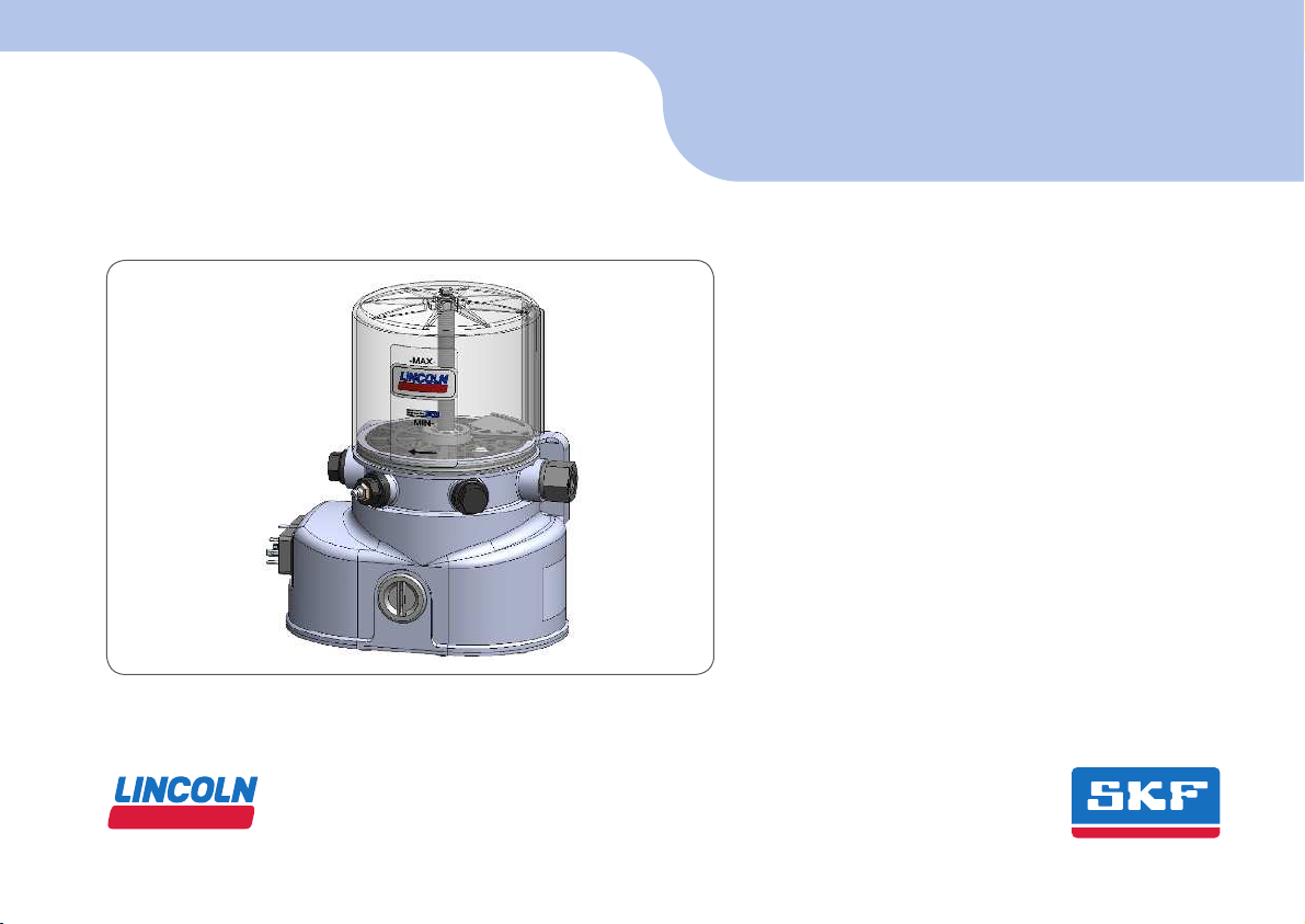
Piston pump P502
ENEN
Installation instructions
following machinery directive 2006/42/EC
951-171-009-EN
Version 11
2016/06/29
Page 2

2
EN
EC Declaration of incorporation
EC Declaration of incorporation following machinery directive 2006/42/EC, annex II, part 1 B
The manufacturer, SKF Lubrication Systems Germany GmbH, Walldorf Facilities, Heinrich-Hertz-Str. 2-8, DE - 69190 Walldorf, hereby declares that the
partly completed machinery
Designation: Pump to supply lubricant within a centralized lubrication system
Type: P502
Part number: 658-XXXXX-X
Year of construction: See type identification plate
complies with the following basic safety and health requirements of the EC machinery directive 2006/42/EC at the time when first being launched in the
market.
1.1.2 · 1.1.3 · 1.3.2 · 1.3.4 · 1.5.1 · 1.5.6· 1.5.8 · 1.5.9 · 1.6.1 · 1.7.1 · 1.7.3 · 1.7.4
The special technical documents were prepared following Annex VII part B of this directive. Upon justifiable request, these special technical documents can be
forwarded electronically to the respective national authorities. The person empowered to assemble the technical documentation on behalf of the manufacturer is the head of standardization. See manufacturer's address.
Furthermore, the following directives and harmonized standards were applied in the respective applicable areas:
2011/65/EU RoHS II
2014/30/EU Electromagnetic compatibility | Industry
2006/28/EC Electromagnetic compatibility | Automotive
Standard Edition Standard Edition
Standard Edition Standard Edition
DIN EN ISO 12100 2011 DIN EN 60947-5-1 2010
DIN EN 61000-6-2 2006 DIN EN 61000-6-4 2011
DIN EN ISO 809 2012 DIN EN 61131-2 2008 Amendment 2011 DIN EN 60947-5-1 2010
DIN EN 60204-1 2007 Amendment 2009 DIN EN 61000-6-3 2011
Amendment 2010 DIN EN 60034-1 2011 Amendment 2012
DIN EN ISO 50581 2013 DIN EN 61000-6-1 2007
The partly completed machinery must not be put into service until the final machinery into which it is to be incorporated has been declared in conformity with
the previsions of machinery directive 2006/42/EC and any other applicable directives.
Walldorf, April 20, 2016
Jürgen Kreutzkämper
Manager R&D Germany
SKF Lubrication Business Unit
Stefan Schürmann
Manager R&D Hockenheim/Walldorf
SKF Lubrication Business Unit
Page 3

3
Legal disclosure
EN
Legal disclosure
The instructions following machinery directive 2006/42/EC are part of the described
product and must be kept at an accessible
location for further use.
Warranty
The instructions do not contain any information on the warranty. This can be found
in our general terms and conditions.
© Copyright SKF
All rights reserved.
Manufacturer
SKF Lubrication Systems Germany GmbH
Walldorf Facilities
Heinrich-Hertz-Str. 2-8
DE - 69190 Walldorf
Phone: +49 (0) 6227 33-0
Fax: +49 (0) 6227 33-259
E-mail: Lubrication-germany@skf.com
www.skf.com/lubrication
Page 4

4
EN
Table of contents
Table of contents
1. Safety instructions ................................................................................................8
1.1 General safety instructions ................................................................................8
1.2 General behaviour when handling the product ...............................................8
1.3 Qualified technical personnel ............................................................................9
1.4 Electric current hazard ....................................................................................10
1.5 System pressure hazard ................................................................................. 10
1.6 Prohibition of certain activities ....................................................................... 10
1.7 Operation .......................................................................................................... 10
1.8 Emergency stopping of the pump .................................................................. 10
1.9 Assembly, maintenance, malfunctions, shutdown, disposal....................... 11
1.10 Intended use ..................................................................................................... 12
1.11 Foreseeable misuse ......................................................................................... 12
1.12 Disclaimer of liability ....................................................................................... 12
1.13 Referenced documents ................................................................................... 12
1.14 Residual risks ................................................................................................... 13
2. Lubricants ...........................................................................................................15
2.1 General safety instructions ............................................................................ 15
2.2 Selection of lubricants ..................................................................................... 15
2.3 Approved lubricants ........................................................................................ 16
2.4 Lubricants and the environment ................................................................... 17
2.5 Lubricant hazard .............................................................................................. 17
3. Overview, functional description ........................................................................18
3.1 Described versions .......................................................................................... 18
4. Technical data .....................................................................................................24
4.1 General technical data ..................................................................................... 24
4.2 Electrics ............................................................................................................ 25
4.3 Output volumes ............................................................................................... 25
4.4 Factory settings of lube and pause times of pumps with control pcb ........ 26
4.5 Specified settings of lube and pause times of pumps with control pcb ..... 26
4.6 Possible settings of lube and pause times of pumps with control pcb ...... 27
4.7 Tightening torques .......................................................................................... 28
4.8 Lubricant requirement for priming of an empty pump ............................... 28
4.9 Useable reservoir volume ............................................................................... 29
4.10 Notes related to the type identification plate ................................................ 30
4.11 Notes related to the CE marking .................................................................... 30
4.12 Type identification code ................................................................................... 31
5. Delivery, returns, and storage ............................................................................32
5.1 Delivery ............................................................................................................. 32
5.2 Returns ............................................................................................................ 32
5.3 Storage ............................................................................................................. 32
6. Assembly .............................................................................................................33
6.1 General information ........................................................................................ 33
6.2 Attachment ....................................................................................................... 33
6.3 Minimum assembly dimensions .................................................................... 33
6.4 Connecting dimensions ................................................................................... 35
6.5 Installing the pump elements ......................................................................... 36
6.6 Installing the pressure reducing valves ......................................................... 37
6.7 Installing the centralized lubrication system ................................................ 38
6.8 Electrical connection ....................................................................................... 39
6.9 Priming without follower plate ....................................................................... 40
6.10 Priming with follower plate ............................................................................. 41
6.11 Setting of lubrication and pause times ......................................................... 43
6.11.1 Pumps without control pcb ............................................................................. 43
6.11.2 Pumps with control pcb .................................................................................. 43
6.11.3 Jumper settings .............................................................................................. 44
7. Start-up ..............................................................................................................45
7.1 General information ........................................................................................ 45
Page 5

5
EN
Table of contents
7.2 Inspections prior to initial start-up ................................................................ 45
7.3 Triggering and additional lubrication cycle ................................................... 45
8. Operation, shutdown and disposal .....................................................................46
8.1 General information ........................................................................................ 46
8.2 Filling the reservoir during operation ............................................................ 46
8.3 Temporary shutdown ...................................................................................... 46
8.4 Shutdown and disposal ................................................................................... 46
9. Maintenance, cleaning and repair ......................................................................47
9.1 General information ........................................................................................ 47
9.2 Cleaning ............................................................................................................ 47
9.3 Maintenance ..................................................................................................... 47
9.4 Replacement of pressure relief valves and pump elements ....................... 47
9.5 Replacement of the control pcb ..................................................................... 48
9.6 Tests after replacement of the control pcb ................................................... 49
9.7 Disposal of disassembled parts ...................................................................... 49
9.8 Replacement of reservoir with follower plate ............................................... 50
9.9 Replacement of the follower plate ................................................................. 51
9.10 Replacement of reservoir without follower plate ......................................... 52
10. Troubleshooting ................................................................................................ 53
10.1 Display of the operating states and fault conditions by means
of the control pcb's LEDs ................................................................................. 56
11. Spare parts .......................................................................................................58
11.1 Pump elements (including sealing ring) ........................................................ 58
11.2 Pressure reducing valve .................................................................................. 58
11.3 Adaptor with lubrication fitting ......................................................................58
11.4 Spare parts kit for replacement of the reservoir .......................................... 59
11.5 Spare parts kit for replacement of the follower plate .................................. 59
11.6 Spare parts kit for replacement of the control pcb ...................................... 59
11.7 Spare parts kit for replacement of the screw cap ........................................ 60
12. Circuit diagrams................................................................................................61
12.1 Legend ............................................................................................................. 61
12.2 Core assignment of the connection plugs ..................................................... 62
12.3 Assignment of circuit diagrams to the pump ................................................ 63
12.4 Circuit diagram 12/ 24 V DC, with bayonet plug and control pcb V20 ...... 64
12.5 Circuit diagram 12/ 24 V DC, with bayonet plug and control pcb V10 ...... 65
12.6 Circuit diagram 12/ 24 V DC, with square plug and control pcb V20 ........ 66
12.7 Circuit diagram 12/ 24 V DC, with square plug and control pcb V10 ........ 67
12.8 Circuit diagram 24 V DC, with M12 plug and control pcb V20 ................... 68
12.9 Circuit diagram 24 V DC, with M12 plug without control pcb .................... 69
12.10 Circuit diagram 12/ 24 V DC, with square plug without control pcb ......... 70
12.11 Circuit diagram 12/ 24 V DC, with bayonet plug without control pcb ....... 71
12.12 Circuit diagram 12/ 24 V DC, with bayonet plug without control pcb ....... 72
Notes ........................................................................................................................... 73
Page 6
6
EN
Explanation of symbols and signs
Explanation of symbols and signs
Symbols
Meaning
General warning
Electrical component hazard, electrical shock hazard
Slipping hazard
Hazard from hot surfaces
Hazard from unintentional intake
Crushing hazard
Pressure injection hazard
Wear personal protective equipment (goggles)
Note
Environmentally sound disposal
recycling
Environmentally sound disposal of
waste electrical and electronic
equipment
You will find these symbols, which warn of
specific dangers to persons, material assets,
or the environment, next to all safety instructions in these operating instructions.
Please read these instructions thoroughly
and heed the warning and safety notes.
Please observe the warning and safety
notes and exercise particular caution in
these cases.
Inform also other users accordingly.
Symbol
Meaning
Prompts an action
Used for itemizing
Refers to other facts, causes, or consequences
Provides additional information within procedures
Warning level Consequence Probability
DANGER
Death/ serious injury imminent
WARNING
Death/ serious injury possible
CAUTION
Minor injury possible
NOTICE
Property damage possible
Symbol
Page 7

7
EN
Explanation of symbols and signs
Abbreviations and conversion factors
Abbreviations
re. regarding oz. Ounce
approx. approx. psi pounds per square inch
°C degrees Celsius rh relative humidity
cu.in cubic inch s second
dB (A) Sound pressure level sq.in. square inch
i.e. that is etc. et cetera
etc. et cetera e.g. for example
poss. possibly > greater than
°F degrees Fahrenheit < less than
fl.ou fluid once ± plus or minus
fpsec feet per second Ø diametre
gal. gallon mph miles per hour
if appl. if applicable rpm revolutions per minute
hp horse power
a.a.r. as a rule
in. inch Conversion factors
incl. including Length 1 mm = 0.03937 in.
K Kelvin Area 1 cm² = 0.155 sq.in
kg kilogram Volume 1 ml = 0.0352 fl.oz.
kp kilopond 1 l = 2.11416 pints (US)
kW kilowatt Mass 1 kg = 2.205 lbs
l litre 1 g = 0.03527 oz.
lb. pound Density 1 kg/cc = 8.3454 lb./gal(US)
max. maximum 1 kg/cc = 0.03613 lb./cu.in.
min. minimum Force 1 N = 0.10197 kp
min. minute Speed 1 m/s = 3.28084 fpsec.
ml millilitre 1 m/s = 2.23694 mph
ml /d millilitre per day Acceleration 1 m/s² = 3.28084 ft./s²
mm millimetre Pressure 1 bar = 14.5 psi
N Newton Temperature °C = (°F-32) x 5/9
Nm Newtonmeter Output 1 kW = 1.34109 hp
Page 8

8
ENEN
1. Safety instructions
1.1 General safety instructions
The owner must ensure that safety information has been read by any persons
entrusted with works on the product or by
those persons who supervise or instruct
the before-mentioned group of persons. In
addition, the owner must also ensure that
the relevant personnel are fully familiar with
and have understood the contents of the
Instructions.
The instructions must be kept at hand together with the product for future reference.
The Instructions are part of the product and
must accompany the product when selling it.
The described products were manufactured
according to the state of the art.
Risks may, however, arise from its usage
and may result in harm to persons or damage to material assets.
Any malfunctions which may affect safety
must be remedied immediately. In addition
to these Instructions, general statutory regulations and other regulations for accident
prevention and environmental protection
must be observed.
1.2 General behaviour when handling the
product
○ The product may be used only in aware-
ness of the potential dangers, in proper
technical condition, and according to the
information in these instructions.
○ Technical personnel must familiar-
ize themselves with the functions and
operation of the product. The specified
assembly and operating steps and their
sequences must be observed.
○ Any unclear points regarding proper
condition or correct assembly/ operation
must be clarified. Operation is prohibited
until issues have been clarified.
○ Unauthorized persons must be kept
aw ay.
○ Precautionary operational measures and
instructions for the respective work must
be observed.
○ Responsibilities for different activities
must be clearly defined and observed.
Uncertainty seriously endangers safety.
○ During operation, safety-related protec-
tive and emergency devices must not be
removed, modified or affected otherwise
in their function and are to be checked at
regular intervals for completeness and
function.. If protective and safety equipment has to be dismantled, it must be
reassembled immediately after finishing
the work, and then checked for correct
function.
○ Remedy occurring faults in the frame of
responsibilities. Immediately inform your
superior in the case of faults beyond your
competence.
○ Wear personal protective equipment
always.
○ When handling lubricants, adhere to the
respective safety data sheets.
1. Safety instructions
Page 9

9
1
ENEN
Only qualified technical personnel may
install, operate, maintain, and repair the
products described in this document. Qualified technical personnel are persons who
have been trained, assigned, and instructed
by the operator of the final product. Such
persons are familiar with the relevant standards, rules, accident prevention regulations,
and assembly conditions as a result of their
training, experience, and instruction. They
are qualified to carry out the required activities and in doing so recognize and avoid any
potential hazards. The definition of qualified personnel and the prohibition against
employing non-qualified personnel are laid
down in DIN VDE 0105 and IEC 364.
Relevant country-specific definitions of
qualified technical personnel apply for coun-
tries outside the scope of DIN VDE 0105 or
IEC 364.
The core principles of these country-specific
qualification requirements for technical
personnel cannot be below those of the two
standards mentioned above.
The operator of the final product is responsible for assigning tasks and areas of
responsibility and for the responsibility and
monitoring of the personnel. These areas
must be precisely specified by the operator.
The personnel must be trained and instructed if they do not possess the required
knowledge.
Product training can also be performed by
SKF in exchange for costs incurred.
1. Safety instructions
Page 10

10
ENEN
1.5 System pressure hazard
1.4 Electric current hazard
1.6 Prohibition of certain activities
The following activities may be carried out
by authorized SKF employees only.
○ Replacement of or changes on the pis-
tons of the pump elements
For pumps with control printed circuit board:
○ Changes on the control printed circuit
board exceeding adjustment of the lubrication and pause times or the replacement in case of defects.
WARNING
System pressure
The product is pressurized during
operation. It must be depressurized before starting assembly,
maintenance, or repair works.
CAUTION
Electric shock
Working on products not disconnected from the power supply may
cause personal injury and damage
to property.
Assembly, maintenance, and repair works may be performed by
qualified and authorized personnel
only on products previously disconnected from the power supply.
Electrical connection may be carried out
only by a qualified electrician authorized by
the operator under consideration of the local
connection conditions and legal prescriptions (e.g. VDE/ IEC).
1.7 Operation
The following must be observed during
commissioning and operation.
○ All information within this manual and
the information within the referenced
documents.
○ All laws and regulations that the operator
must observe.
1.8 Emergency stopping of the pump
In case of an emergency stop the pump by:
○ actuating the emergency stop switch of
the superior machine.
○ switching off the machine or vehicle, in
which the pump has been integrated.
○ disconnecting the pump from the power
supply.
1. Safety instructions
Page 11

11
1
ENEN
○ All relevant persons (e.g. operating per-
sonnel, supervisors) must be informed
of the activity prior to starting any work.
Precautionary operational measures and
work instructions must be observed.
○ Ensure through suitable measures that
moving/ detached parts are immobilized
during the work and that no body parts
can be caught in between by unintended
movements.
○ Assemble the product only outside of the
operating range of moving parts, at an
adequate distance from sources of heat
or cold.
○ Prior to performing work, the product
and the machine or system in which the
product is or will be integrated must be
depressurized and secured against unauthorized activation.
○ Carry out works on electrical compo-
nents with voltage isolated tools only.
○ Ensure proper grounding of the product.
○ Drill required holes only on non-critical,
non-load bearing parts.
○ Other units of the superior machine
must not be damaged or impaired in
their function by the installation of the
product.
○ No parts of the centralized lubrication
system may be subjected to torsion,
shear, or bending.
○ Use adequate lifting devices when work-
ing with heavy components.
○ Avoid mixing up or wrong assembly of
disassembled parts.
Mark parts properly.
1.9 Assembly, maintenance, malfunctions, shutdown, disposal
1. Safety instructions
Page 12

12
ENEN
1.10 Intended use
Supply of lubricants within a centralized
lubrication system in intermittent operation
following the specifications made in these
Instructions:
○ to establish a progressive system
○ as a multi-line pump for direct supply to
individual lubrication points.
1.11 Foreseeable misuse
Any usage of the product differing from
the aforementioned conditions and stated
purpose is strictly prohibited. Particularly
prohibited are:
○ Use in an explosive atmosphere
○ Use without the integrated pressure re-
ducing valve
○ Use in continuous operation
○ Painting the pump. Remove or tape
pump completely before painting the su-
perior machine
○ to supply, transport, or store hazardous
substances and mixtures in accordance
with annex I part 2-5 of the CLP regula-
tion (EC 1272/2008).
○ Use to feed, forward, or store gases,
liquefied gases, dissolved gases, va-
pours, or fluids whose vapour pressure
exceeds normal atmospheric pressure
(1013 mbar) by more than 0.5 bar at
the maximum permissible operating
temperature.
○ Use to feed, forward, or store glycol- or
polyglycol based oils and greases. These
may damage the reservoir.
1.12 Disclaimer of liability
The manufacturer shall not be held responsible for damages caused by:
○ inappropriate usage
○ wrong or improper assembly, op-
eration, adjustment, programming, or
maintenance
○ improper or late response to
malfunctions
○ unauthorized modification of system
components
○ the installation of non-original SKF com-
ponents or spare parts
1.13 Referenced documents
In addition to these instructions, the following documents must be observed by the
respective target group:
○ Operational instructions and approval
rules
○ Safety data sheet (MSDS) of the lubricant
or material used
If applicable
○ Instructions of suppliers of purchased
parts, project planning documents and
other relevant documents.
The operator must supplement these documents with applicable national regulations
for the country of use. When selling or forwarding the product, make sure to attach
these Instructions to it.
1. Safety instructions
Page 13
13
1
ENEN
1.14 Residual risks
Residual risks Remedy
Life cycle — transport, assembly, start-up, operation, malfunction, troubleshooting, repair, maintenance, shutdown, disposal
Dropping of lifted parts or tools ○ No people may remain under suspended loads. Keep unauthorized persons away. Secure suspend-
ed loads using suitable hoisting equipment (e.g. tapes, belts, ropes, etc.).
Falling of parts through insufficient fixing to
the machine
○ Fix parts only to machine parts with sufficient load capacity. Observe the weight. Observe the stated
tightening torques. If no tightening torques are stated, the tightening torques are to be applied to
the screw size for 8.8 screws. Literature, see screw manufacturer.
Electrical shock due to defective connection
cable
○ Check connection cable for damages.
People slipping due to floor contamination
with spilled or leaked lubricant
○ Exercise caution when disconnecting or connecting the product's hydraulic connections
○ Promptly apply suitable binding agents to remove the leaked or spilled lubricant
○ Follow the operational instructions for handling lubricants and contaminated parts
Tearing or damaging of lines when installed
on moving machine parts
○ If possible, do not install on moving parts. If this cannot be avoided, use flexible hose lines
Ripping out/ damage to lines at chafing
points or due to assembly with too little
bending radius
○ Use protective pipes or spring coils
Lubricant spraying out due to faulty component fitting or line connection
○ Use hydraulic fittings and lines suitable for the indicated pressures. These must be checked for
proper connection and damage prior to commissioning
Bursting reservoir if filled by a high-performance pump
○ Monitor the filling procedure and stop it when reaching the max marking of the reservoir
1. Safety instructions
Page 14
14
ENEN
Residual risks Remedy
Life cycle — transport, assembly, start-up, operation, malfunction, troubleshooting, repair, maintenance, shutdown, disposal
Contact with stirring paddle during "test operation" without reservoir after repair.
○ Operate pump with reservoir always
Reservoirs with follower plate are subjected
to spring load
○ Remove reservoir only when spring is quite released, i.e. the reservoir is empty. If necessary, empty
the reservoir first. Provide adequate protective measures - e.g. fastening straps - when loosening
the reservoir. Do not work with your head directly above the reservoir
Contamination of the environment with lubricant and wetted parts
○ Dispose of the parts following the relevant legal/ operational regulations
Strong heating of the motor
due to a blockade
○ Switch pump off, let parts cool down, eliminate cause.
Damage of the control pcb due to electrostatic discharge when replacing a defective
control pcb
○ Avoid electrostatic charge. Use ESD tools and ESD protective clothes, wear a grounding bracelet
Loss of electrical protective functions due to
faulty installation of the control pcb
○ After the installation carry out a safety check following DIN EN 60204-1 (conduct and scope of test,
see chapter 9.6)
1. Safety instructions
Page 15
15
121
ENEN
2. Lubricants
2.1 General safety instructions
Intended use is the use of the products to
lubricate bearings and friction points with
lubricants within the physical limits that
can be found in the relevant product documentation, e.g. operating instructions and
product descriptions, e.g. technical drawings
and catalogues.
Particular attention is called to the fact that
hazardous materials of any kind, especially
those materials classified as hazardous by
CLP Regulation EC 1272/2008 annex I,
part 2-5 may be filled into SKF centralized
lubrication systems and components and
delivered and/ or distributed with such systems and components only after consulting
with and obtaining written approval from
SKF.
Selection of a lubricant suitable for the
lubrication task is made by the machine or
system manufacturer and/or the operator of
the machine or system in cooperation with
the lubricant supplier.
When selecting a lubricant, the type of
bearings or friction points, the expected
load during operation, and the anticipated
ambient conditions must be taken into ac-
count. All economic and environmental
aspects must also be considered.
NOTICE
Observe the instructions from the machine
manufacturer regarding the lubricants to
be used.
The amount of lubricant required at the
lube point is specified by the bearing or
machine manufacturer. It must be ensured
that the required lubricant volume is provided to the lubrication point. Otherwise
the lubrication point may not receive adequate lubrication, which can lead to damage and failure of the bearing.
2.2 Selection of lubricants
NOTICE
All products may be used only for their intended purpose and in accordance with the
Instructions.
All products manufactured by SKF are not
admitted for use in combination with gases,
liquefied gases, dissolved gases, vapours, or
fluids whose vapour pressure exceeds normal atmospheric pressure (1013 mbar) by
more than 0.5 bar at the maximum permissible operating temperature.
Other material which is neither lubricant nor
hazardous substance may be fed only after
consultation with and written approval by
SKF.
SKF considers lubricants to be an element
of system design that must always be
factored when selecting components and
designing a centralized lubrication system.
The lubricating properties of the lubricants
are critically important when making these
selections.
1. Safety instructions
2. Lubricants
Page 16
16
EN
Please contact SKF if you have further
questions regarding lubricants. It is possible
for lubricants to be tested in the company's
laboratory for their suitability for being
pumped in centralized lubrication systems
(e.g. "bleeding").
You can request an overview of the lubricant
tests offered by SKF from the company's
service department.
The product described here can be operated
using lubricants that meet the specifications in the technical data. Depending on the
product design, these lubricants may be oils,
fluid greases, or greases.
Mineral, synthetic, and/or rapidly biodegradable oils and base oils can be used. Consistency agents and additives may be added
depending on the operating conditions.
Note that in rare cases there may be lubricants whose properties are within permissible limit values but whose other characteristics render them unsuitable for use in
centralized lubrication systems. For example, synthetic lubricants may be incompatible with elastomers.
NOTICE
Only lubricants approved for the product
may be used. Unsuitable lubricants can
lead to failure of the product and to property damage.
2.3 Approved lubricants
NOTICE
Different lubricants must not be mixed.
Doing so may cause damage and require
costly and complicated cleaning of the
product or lubrication system. It is recommended that an indication of the lubricant
in use be attached to the lubricant reservoir in order to prevent accidental mixing
of lubricants.
NOTICE
If required SKF can help customers to
select suitable components for feeding the
selected lubricant and to plan and design
their centralized lubrication system.
2. Lubricants
Page 17
17
121
ENEN
2.5 Lubricant hazard2.4 Lubricants and the environment
NOTICE
Lubricants may pollute ground and waters.
Lubricants have to be handled and disposed of properly. Observe the instructions
by the machine manufacturer regarding
the lubricants to be used.
It is important to note that lubricants are
environmentally hazardous, flammable
substances that require special precautionary measures during transport, storage,
and processing. Consult the safety data
sheet from the lubricant manufacturer for
information regarding transport, storage,
processing, and environmental hazards of
the lubricant that will be used.
The safety data sheet of a lubricant may be
requested from the lubricant manufacturer.
WARNING
Risk of slipping and injury
Leaking lubricant is hazardous due
to the risk of slipping and injury.
Seal leaks without delay and remove spilled or leaked lubricant.
1. Safety instructions
2. Lubricants
Page 18
18
EN
3. Overview, functional description
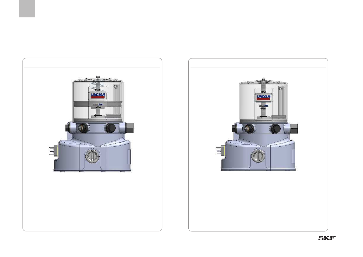
3.1 Described versions
- with follower plate and low level signal (1XLF)
- with and without controller
- 12 / 24 V DC
P502 with follower plate Fig. 1
- without follower plate and without low level signal
(1XLF)
- with and without controller
- 12 / 24 V DC
P502 without follower plate Fig. 2
3. Overview, functional description
Page 19
19
3
EN
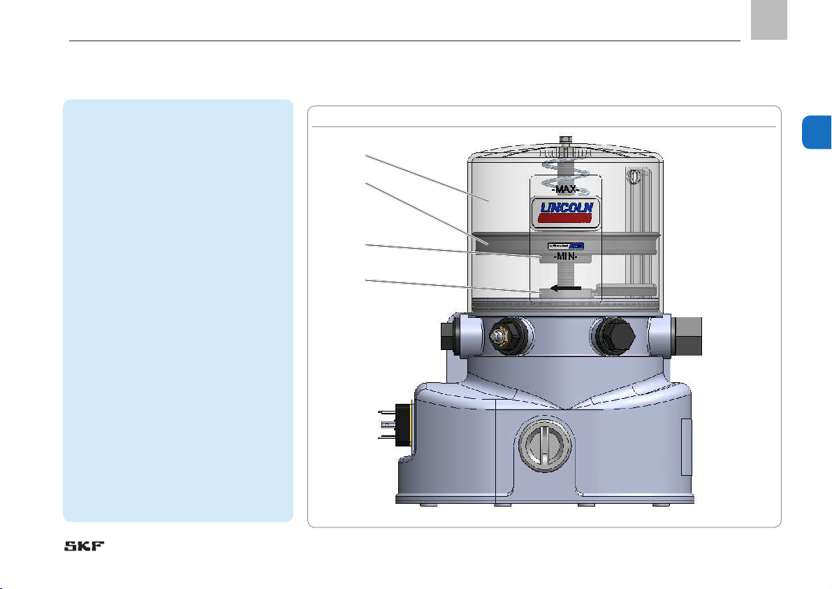
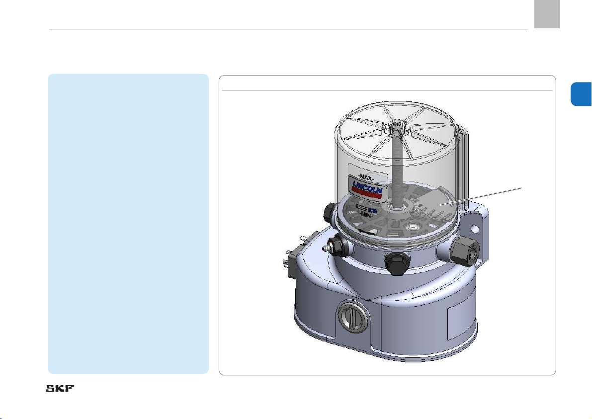
Overview P502 with follower plate Fig. 3
1 Reservoir
The lubricant is stored in the reservoir. Depending on the pump version there are three
different types of reservoirs.
XN 1 L for lubricating grease
YN 1 L for lubricating oil
XLF 1 L with follower plate and low level signal
for lubricating grease.
2 Follower plate (in case of models with follower plate)
The spring-loaded follower plate pushes the
lubricant down into the pump elements. This
improves the suction behaviour of the pump.
Pumps with follower plate can be used also
in rotating applications (e.g. wind turbine
generators).
3.1 /3.2 Magnet and magnetic switch
for low level signal
The low level signal is enabled without contact
by means of a magnet (3.1 in the follower plate
and a magnetic switch (3.2) in the pump housing. As soon as the MIN reservoir filling level is
reached, a low level signal is triggered.
1
2
3.1
3.2
3. Overview, functional description
Page 20
20
EN
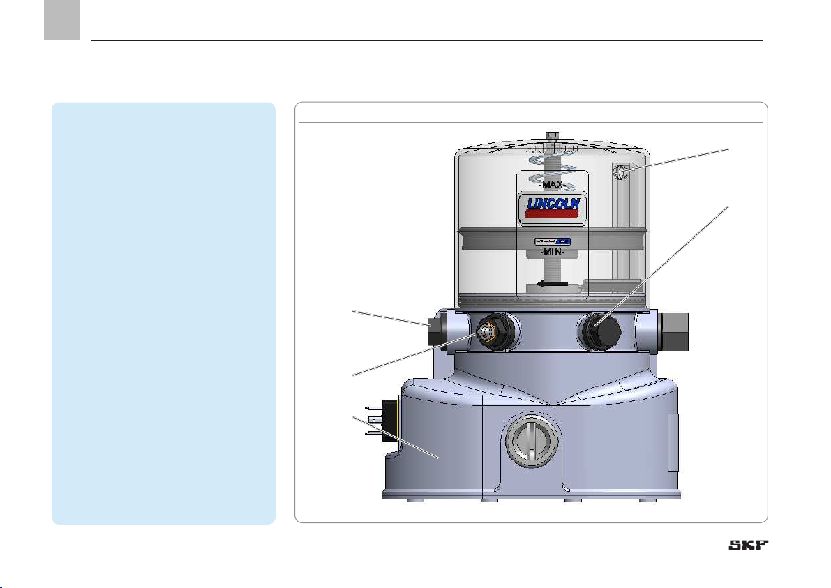
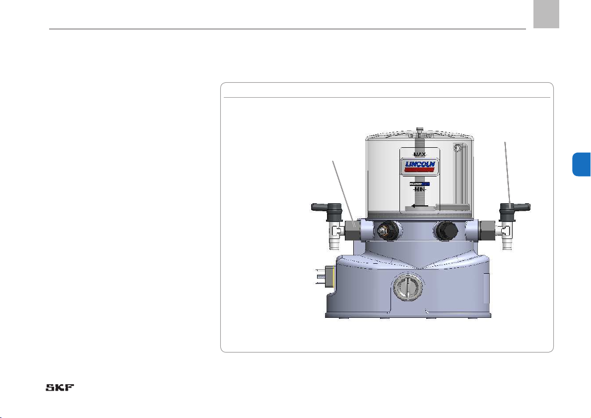
Overview P502 with follower plate Fig. 4
4 Closure screw
When using the pump with one pump element
only make sure to close the connection port for
the second pump element with a closure screw.
5 Filler fitting (R1/4)
The filler fitting serves to fill the reservoir with
lubricant.
6 Pump housing
Comprises the motor and, depending on the
pump version, different control pcbs and different connecting options (square or bayonet
plug or
M 12 plug).
7 Reservoir venting device
Is used to vent the reservoir when filling it
with lubricant or to vent the reservoir during
operation.
8 Return-line connection
Is used to connect a return line or to fill the
reservoir via a manual pump with corresponding adaptor. When delivering the pump the
return-line connection is closed with a closure
screw (4).
8/4
7
4
5
6
3. Overview, functional description
Page 21
21
3
EN
Overview P502 with follower plate Fig. 5
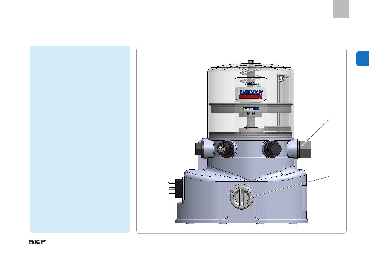
9
10
9 Pump element
There can be mounted a maximum of 2 pump
elements. The pump elements are actuated
by the motor via an eccentric shaft. The pump
elements generate the operating pressure and
supply the lubricant out of the reservoir to the
connected lubrication feed lines. Each pump
element has to be secured by a pressure reducing valve following the maximum operating
pressure.
10 Cover plate of control printed circuit board
The transparent cover plate of pumps with control unit allows to see the operating and error
states (LED displays on the control pcb).
Remove the cover plate (10) from the control
pcb to trigger an additional lubrication cycle or
to adjust lubrication and pause times.
3. Overview, functional description
Page 22
22
EN
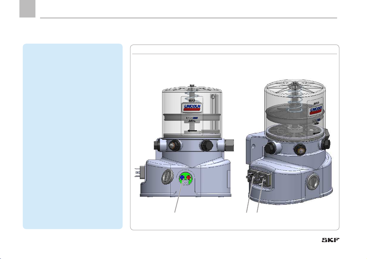
Overview P502 Fig. 6
11 Control pcb
All control pcbs are equipped with an EEPROM.
Thus the pcb's data are protected against loss.
As soon as the pump is switched off, after
switching the pump on again the pause time
respectively the lubrication time will continue
from where it had been interrupted.
Electrical connections
The electrical connections (28/ 29) on the left
respectively on the right side of the pump housing have been provided for connection to the external power supply (28) and to external control
or output devices (29) (e.g. PLC signal lamp)
11
28 29
3. Overview, functional description
Page 23
23
3
EN
Overview P502 Fig. 7
26 Stirring paddle
The stirring paddle homogenizes and planes
the lubricant. Transportability of the lubricant is
improved and bleeding is reduced.
26
3. Overview, functional description
Page 24

24
EN
4. Technical data
4.1 General technical data
Admissible operating temperature -25 °C to 70 °C
Operating pressure 270 bar max.
Reservoir size 1 litre
Filling of reservoir
via hydraulic lubrication fitting
(optionally via cartridge with fitting or filling connection)
Lubricants Lubricating greases NLGI II and NLGI III
1)
/ fluid greases NLGI 00, 000
Connections
2 x pump element with connection for feed line G 1/4”
1 x filling connection for cartridge M 22x1.5
1 x filling connection with hydraulic lubrication fitting R 1/4
Feed lines Plastic/ steel tube Ø 6 mm or Ø 8 mm
Installation position (pump without follower
plate)
Reservoir on top. Deviation ± 5° max.
Installation position (pump without follower
plate)
any
2)
Sound pressure level < 70 dB (A)
Weight (empty) approx. 4 kg
Speed 9 ± 1 rpm
-1
1)
NLGI III lubricants can be supplied under certain application conditions only. These application conditions have to be clarified with SKF in
advance.
2)
also rotating installation, like e.g. in wind turbine generators. Maximum speed and maximum distance to the hub on request.
4. Technical data
Page 25

25
4
EN
4.2 Electrics
Supply voltage 12 V DC 24 V DC
Current consumption 6.5 A maximum 3 A max.
Tolerance of input voltage -20 / + 30 % -20 / + 30 %
Inputs protected against reverse polarity, short circuit proof, non-isolated
IP type of protection Square plug IP 6K9K
bayonet plug IP 65
M12 plug IP 67
Internal fusing none
External fusing (provided by owner) 6 A (T) 3 A (T)
Types of protection SELV, PELV, FELV
4.3 Output volumes
Deviating operating conditions or deviated pump configuration result in a changed motor speed in the frame of the tolerances indicated in
chapter 4.1. This influences the actual output per minute. If as a consequence the output needs to be adapted, this will be done by adapting the lubrication and pause time settings of the pump.
The stated outputs refer to NLGI II lubricating greases at an operating temperature of + 20 °C and a backpressure of 100 bar.
Output quantities per pump element per stroke Factors influencing the output quantity (motor speed)
Pump element K5 0.12 cc Operating temperature > + 20 °C
á
< + 20 °C
â
Pump element K6 0.18 cc Consistency class of lubricant > NLGI II
â
< NLGI II
á
Pump element K7 0.24 cc Backpressure < 100 bar
á
> 100 bar
â
Pump element B7 0.10 cc Number of pump elements > 1 piece
â
Pump element C7 0.24 cc
4. Technical data
Page 26

26
EN
4.4 Factory settings of the lubrication and pause times of pumps with control pcb
Lubrication and pause times
Lubrication time 6 min The red rotary switch on the control pcb is in position 3
pause time 6 hrs The blue rotary switch on the control pcb is in position 6
Low level signal
After a low level signal the run time is 4 min max. When the time has lapsed, the control unit stops the pump until the low level
signal turns off due to filling of the reservoir.
Lubrication and pause times
The following values are to be met by the external control unit to avoid damages to the pump.
Lubrication time 8 sec min. 30 min max.
pause time 4 sec min.
Low level
The owner has to ensure that the pump is stopped by the external control unit latest 4 min after the low level signal.
4. Technical data
Page 27

27
4
EN
4.6 Possible settings of the lubrication and pause times of pumps with control pcb
Position of the rotary switch (blue) 1 2 3 4 5 6 7 8 9 A B C D E F
Pause time in minutes
3)
4 8 12 16 20 24 28 32 36 40 44 48 52 56 60
Position of the rotary switch (blue) 1 2 3 4 5 6 7 8 9 A B C D E F
Pause time in hours
3)
1 2 3 4 5 6 7 9 9 10 11 12 13 14 15
Position of the rotary switch (red) 1 2 3 4 5 6 7 8 9 A B C D E F
Lubrication time in seconds
3)
8 16 24 32 40 48 56 64 72 80 88 96 104 112
120
Position of the rotary switch (red) 1 2 3 4 5 6 7 8 9 A B C D E F
Lubrication time in minutes
3)
2 4 6 8 10 12 14 16 18 20 22 24 26 28 30
3)
Time values for pause and lubrication times are factory-set via the jumpers on the control pcb
(see chapter 6.11.3). The positions of the jumpers must not be changed by the owner.
Reference to the "0" position of the rotary switches
Never turn the rotary switches in the "0" position. This position is intended exclusively for the owner's purposes.
In the "0" position the pump operates with the factory settings (see chapter 4.3) and fault F2
(see chapter 10.1) is indicated by the control pcb's LEDs.
4. Technical data
Page 28

28
EN
4.7 Tightening torques
Adhere to the following tightening torques when installing or repairing the pump.
Pump with base plate, machine, or vehicle 18 Nm
Pump element with pump housing 20 Nm
Counter nut at the adjustable pump element
12 Nm
Pressure reducing valve in the pump element
8 Nm
Lubrication fitting/ adaptor for lubrication fitting
10 Nm
Closure screw on housing cover
0.8 Nm
Reservoir on Reservoir axis 2+1 Nm
4.8 Lubricant requirement for priming of an empty pump
To prime an empty pump up to the MAX marking of the reservoir, the following lubricant quantities are required.
1XLF
with follower plate and low level indication
1XN
without follower plate and without low level
indication
approx. 1.25 litres approx. 1.4 litres
The deviation between the lubricant quantity actually required for priming and the nominal volume of the reservoir results from the filling of the pump housing up to the MIN marking of the reservoir.
4. Technical data
Page 29

29
4
EN
4.9 Useable reservoir volume
Reservoir 1XN (without follower plate and without low level indication)
Regarding reservoir version 1XN the useable reservoir volume mainly depends on the NGLI consistency class and the operating temperature of the
lubricant to be used. In case of high consistency and low operating temperature normally more lubricant sticks to the inner surfaces of the reservoir/ pump and is thus no more available for being dispensed.
Useable reservoir volume
Lubricants with relatively low consistency
4,6)
Approx. 1.0 litres (without vibrations or tilting motions)
Lubricants with relatively low consistency
4)
Approx. 0.5 litres (with stronger vibrations or tilting motions)
Lubricants with relatively high consistency
5)
0.75 litres
4)
Lubricant consistencies of NLGI 000 lubricants at + 70 °C up to lubricant consistencies of NLGI 1.5 lubricants at + 20 °C.
5)
Lubricant consistencies of NLGI 2 lubricants at + 20 °C up to the maximum admissible lubricant consistency.
6)
When using lubricants of a relatively low consistency in pumps subjected to strong vibrations or tilting motions
(e.g. construction and agricultural machinery), make sure to maintain a level that is about 15 mm below the MAX marking of the reservoir. This prevents
lubricant from entering the reservoir vent. In case of very strong vibrations this value must be increased, for low vibrations it can be reduced. Changing the
filling level by 10 mm corresponds to a volume change of about 0.14 litres.
Reservoir 1XLF (with follower plate and low level indication)
In case of reservoir version 1XLF the useable reservoir volume is independent of the lubricant's consistency.
Useable reservoir volume approx. 0.60 litres
4. Technical data
Page 30

30
EN
-
cation plate
The type identification plate states important characteristics such as type designation, order number, etc.
To ensure that the loss of data due to an
illegible type identification plate is avoided,
the characteristics should be entered in the
Instructions.
P. No. ________________________________
S. No. ________________________________
Model ________________________________
Type identification plate Fig. 8
4.11 Notes related to the CE marking
CE marking is effected following the requirements of the applied directives:
○ 2014/30/EU Electromagnetic compatibility
○ 2011/65/EU (RoHS II) Directive on the restriction of the use of certain hazardous
substances in electrical and electronic equipment
Reference on Low Voltage Directive 2014/35/EU
The protective regulations of Low Voltage Directive 2014/35/EU are fulfilled according to annex I (1.5.1) of Machinery Directive 2006/42/EC.
Reference on Pressure Equipment Directive 2014/68/EU
Because of its performance data the product does not achieve the limit values defined in Article 4 (1) (a) (i) and is therefore excluded from the scope of application of
Pressure Equipment Directive 2014/68/EU following Article 4 (3).
4. Technical data
Page 31

31
4
EN
Basic type of pump
P502
Reservoir versions (plastic)
1X N 1L for grease (without follower plate and without low level indication)
1YN 1Lfor oil
1XLF 1L for grease (with follower plate and with low level indication)
Pump elements
... Without pump elements
[X]K5 Piston diameter = 5 mm
[X]K6 Piston diameter = 6 mm
[X]K7 Piston diameter = 7 mm
[X]B7 Piston diameter = 7 mm
[X] Number of pump elements (max. 2)
Supply voltage
12 12 V DC
24 24 V DC
Electrical connections on pump
1A 1 connection
Left side for supply voltage, low level indication and illuminated pushbutton
2A 2 connections
Left side for supply voltage
Right side for low level indication and illuminated pushbutton
Identification code
P502 - 1XN - 2K6 - 12 - 2A - 6 - 14 - V10
Control pcb's
(without control pcb)
(supply voltage, terminals 15+31) V10 - V13
(supply voltage, terminals 15+30+31) V20 - V23
Pump connections to external devices
Square plug with closure cap 00
Square plug with connection socket 01
Square plug with connection socket and 10 m cable
10
Bayonet socket with 10 m cable (4/4 wire) 14
Bayonet socket with 10 m cable (7/5 wire) 15
Bayonet socket with 10 m cable (7/6 wire) 16
Type of connection
Square plug 1
M12 plug 2
Bayonet plug ISO 15170-1, 4/4-pole 5
Bayonet plug ISO 15170-1, 7/5-pole 6
Bayonet plug ISO 15170-1, 7/6-pole 7
4. Technical data
Page 32

32
EN
5. Delivery, returns, and storage
5.1 Delivery
The products are packaged following the
standard commercial practice according to
the regulations of the recipient's country.
During transport safe handling must be
ensured.
After receipt of the shipment, the product(s)
must be inspected for damage and for completeness according to the shipping documents. Keep the packaging material until
any discrepancies are resolved.
5.2 Returns
Clean all parts and pack them properly
before returning them. Protect the product
against mechanical influences such as impacts. There are no restrictions for land, sea
or air transport. Mark returns on the packaging as follows.
5.3 Storage
SKF products are subject to the following
storage conditions:
○ dry and dust-free surroundings, storage
in well ventilated dry area
○ Storage time: 24 months max.
○ Permissible humidity: < 65% (rh)
Storage temperature:
min. - 25 °C/ max. + 70 °C
○ avoid direct sun or UV exposure
○ shield product from nearby sources of
heat and coldness.
General notes related to storage
○ The product(s) can be wrapped in plastic
film to provide low-dust storage.
○ Protection against ground moisture by
storing on a shelf or wooden pallet.
Marking of returns Fig. 9
5. Delivery, returns, and storage
Page 33

33
6
5
EN
6. Assembly
Only qualified technical personnel may
install, operate, maintain, and repair the
products described in these Instructions.
Qualified technical personnel are persons
who have been trained, assigned, and instructed by the operator of the final product,
into which the described product shall be
integrated.
Such persons are familiar with the relevant
standards, rules, accident prevention regulations, and operating conditions as a result
of their training, experience, and instruction.
They are qualified to carry out the required
activities and in doing so recognize and
avoid any potential hazards.
Before assembling the product, the packaging material as well as possible transport
locking devices must be removed.
Keep the packaging material until any discrepancies are resolved.
NOTICE
Technical data (see chapter 4).
6.1 General information
6.2 Attachment
Protect the product against humidity and
vibration and install it in an easily accessible
position to ensure all other installations can
be carried out without any problem. For indications on the maximum admissible ambient temperature see the technical data.
During assembly and particularly during
any drilling work always pay attention to the
following:
○ Other units must not be damaged by the
assembly.
○ The product must not be installed within
the range of moving parts.
○ The product must be installed at an ad-
equate distance from sources of heat and
coldness.
○ Adhere to safety distances and legal pre-
scriptions on assembly and prevention of
accidents.
CAUTION
Electric shock
Make sure to disconnect the product from the power supply before
carrying out works on any part
of it.
Connection of the pump must be
provided by a safe galvanic isolation (PELV) always.
6. Assembly
Page 34

34
EN
Minimum assembly dimensions Fig. 10
6.3 Minimum assembly dimensions
Ensure sufficient space for maintenance work or for a possible disassembly of the product by leaving a free space of at least 50 mm
into each direction in addition to the stated dimensions.
A = height 270 mm
B = width 250 mm
C = depth 150 mm
6. Assembly
Page 35

35
6
EN
Connecting dimensions Fig. 11
6.4 Connecting dimensions
The pump is fastened on the two mounting
bores (27). Fastening is done by means of
the fastening material included in the scope
of delivery.
2 x M8 screw
2 x M8 nut (self-locking)
2 x washer
Tightening torque = 18 Nm
A = height 114 mm
B = distance 140 mm
C = bore Ø 10 mm
A
B
C
27
6. Assembly
Page 36

36
EN
Mount pump elements Fig. 12
6.5 Installing the pump elements
• Remove closure screw (4).
• Screw in pump element (9) with new
sealing ring.
Tightening torque = 20 Nm
• Repeat procedure for each pump
element.
4
9
6. Assembly
Page 37
37
6
EN
6.6 Installing the pressure reducing valves
• Choose pressure reducing valve (13)
in accordance with the max. operating
pressure.
• Remove blind plug from pump element
(9).
• Screw pressure reducing valve (13) into
pump element (9).
Tightening torque = 8 Nm
• Repeat procedure for
each pump element.
Mount pressure reducing valve Fig. 13
9
13
6. Assembly
Page 38

38
EN
Mount the centralized lubrication system Fig. 14
6.7 Installing the centralized lubrication
system
• Fasten the pump. Observe connecting
dimensions (see chapter 6.4).
Tightening torque = 18 Nm
• Make up the divider.
• Fasten the divider.
• Make up the lines and attach them to the
pump and, if applicable, to the superior
machine.
6. Assembly
Page 39

39
6
EN
6.8 Electrical connection
Electrical connections must be done in such
way that no forces are transferred to the
product (tension-free connection). For electrical connection proceed as follows:
Square plug
• Use adequate cable to configure square
plug without cable. For connection of the
cable, see wiring diagram on square plug
or corresponding wiring diagram in these
Instructions (see chapter 12).
• Remove protective caps from the electri-
cal connections of the pump.
• Place plugs with sealing onto connec-
tions and fasten it with the screw of the
square plug.
Bayonet plug
•
plug without cable. For connection see
corresponding wiring diagram in these
Instructions (see chapter 12).
• Remove protective caps from the electrical connections of the pump.
• Place plugs onto connections and fasten
them by turning them.
M12 plug
•
plug without cable. For connection see
corresponding wiring diagram in these
Instructions (see chapter 12).
• Remove protective caps from the electrical connections of the pump.
• Place M12 plugs onto connections and
fasten them by turning them.
NOTE
Electrical characteristics
see chapter 4, Technical data.
6. Assembly
Page 40

40
EN
6.9 Priming without follower plate
The pump is supplied with partial filling
ex works. If specified by the customer the
pump can also be supplied without priming.
In this case it has to be primed according to
the following instructions.
NOTICE
Damage to the pump
Make sure that no dirt enters the reservoir
during the filling procedure.
Consider lubricant expansion by increased
temperature (important, e.g. for storage or
transport of the pump) or by pressure relief
after the filling procedure (reservoir vent
clogged by lubricant).
P502 without follower plate Fig. 15
8
5
Filling via filler fitting
Place filling connection of the filler pump
onto filler fitting R1/4 (5).
• Switch on filler pump and fill reservoir
with lubricant until shortly below the
MAX marking.
• Switch off filler pump and remove filling
connection.
• If applicable, remove leaked lubricant and
dispose of in an environmentally sound
manner.
Filling via filling connection
• Unscrew closure screw from filling connection (8).
• Screw in cartridge.
• Fill reservoir with lubricant until shortly
below the MAX marking.
• Remove cartridge and screw closure
screw into the filling connection.
Tightening torque = 10 Nm
• If applicable, remove leaked lubricant and
dispose of in an environmentally sound
manner.
6. Assembly
Page 41

41
6
EN
Filling via filler fitting
• Ensure that pump stands upright with
the cable strap (30) fixed at the uppermost position.
• Place filling connection of the filler pump
onto filler fitting R1/4 (5).
• Switch on filler pump and completely
fill space below the follower plate with
lubricant (see Fig. 17). The space is fully
filled as soon as the follower plate starts
lifting.
• Switch off filler pump.
6.10 Priming with follower plate
NOTICE
Avoid air pockets under the follower plate.
These result in poor or lacking pump
output.
Make sure that no dirt enters the reservoir during the filling procedure. Switch
pump on only after having removed the
cable straps.
Consider lubricant expansion by increased
temperature (important, e.g. for storage
or transport of the pump) or by pressure
relief after the filling procedure (reservoir
vent clogged/ contamination of the transport packaging by lubricant).
Empty pump with cable strap Fig. 16
5
Filled pump without cable strap Fig. 18
Vented space under the follower plate Fig. 17
30
7
6. Assembly
Page 42

42
EN
• Slowly pull cable strap (30) out of reservoir vent (7) to vent the space below the
follower plate.
• Use filler pump to fill reservoir with
lubricant until shortly below the MAX
marking.
• If applicable, remove leaked lubricant and
dispose of in an environmentally sound
manner.
Filling via filling connection
• Ensure that pump stands upright with
the cable strap (30) fixed at the uppermost position.
• Unscrew closure screw from filling connection (8).
• Screw in cartridge.
• Fill space below the follower plate with
lubricant completely (see Fig. 20). The
space is fully filled as soon as the follower
plate starts lifting.
Empty pump with cable strap Fig. 19
8
Filled pump without cable strap Fig. 21
Vented space under the follower plate Fig. 20
30
• Slowly pull cable strap (30) out of reservoir vent (7) to vent the space below the
follower plate.
• Now fill reservoir with lubricant until
shortly below the MAX marking.
• Remove cartridge and screw closure
screw into the filling connection.
• If applicable, remove leaked lubricant and
dispose of in an environmentally sound
manner.
Tightening torque = 10 Nm
7
6. Assembly
Page 43

43
6
EN
6.11.1 Pumps without control pcb
Setting or modification of the lubrication
and pause times is effected via the external
control unit to be provided by the owner.
When doing so adhere to the values for the
lubrication and pause times stated in chapter 4.5.
6.11 Setting of lubrication and pause times
NOTICE
Damage to the pump
Adhere to the values for the admissible lubrication and pause times stated in chapter
4.4 for pumps without control unit.
6.11.2 Pumps with control pcb
• Setting or modification of the lubrication
and pause times is effected via the internal control pcb.
• Setting of the parameters is done via the
two rotary switches of the control pcb.
(Values, see chapter 4.5).
• Remove closure cap (10) and sealing ring
(14).
• Set the pause time by turning the left
blue rotary switch (20).
• Set the lubrication time by turning the
right red rotary switch (21). (Values, see
chapter 4.5).
• Mount closure cap (10) and sealing ring
(14).
Setting of lubrication and pause times Fig. 22
10/14 20 21
6. Assembly
Page 44

44
EN
6.11.3 Jumper settings
NOTICE
Damage to the pump
The positions of the jumpers on the control
pcb should never be changed. Changed
jumper positions cannot be easily recognized by other persons and may therefore
result in wrong settings of the lubrication
and pause times by means of the rotary
switches of the control pcb.
Jumper position on the control pcb
Jumper position for
bridge
Terminal 15/30
Control
pcb
Pause time Lubrication time
Jumper position
Pause and lubrication time
4 - 60
min.
1 - 15h8-120
sec
2-30
min
V 10
X X
min
min
P h
I S
not bridged V20
V11
X X
min
min
P h
I S
not bridged V21
V12
X X
min
min
P h
I S
not bridged V22
V13
X X
min
min
P h
I S
not bridged V23
= Jumper positioned
* If terminal 15 (machine contact/drive switch) is bridged with terminal 30 (+) and if
voltage is present at terminal 30, then the pump can work without the superior machine/vehicle having to run. Without bridge the pump works only, if also the superior
machine/vehicle runs.
Terminal 15/30
Pause time and lubrication time
6. Assembly
Page 45

45
7
6
EN
7. Start-up
7.1 General information
Start-up of the fully and correctly mounted
pump is effected via the machine contact or
the driving switch.
The pump starts with a pause time. Therefore, after connecting the pump and setting
the required lubrication and pause times,
first of all, a lubrication cycle should be triggered to verify correct pump connection. In
case of pumps without control unit a lubrication cycle is triggered by the PLC of the
superior machine.
7.2 Inspections prior to initial start-up
To ensure optimal performance and safety,
check certain parts of the centralized lubrication system at regular intervals. Report
any detected deficiencies immediately to
your superior and remedy them. Deficiencies may be remedied by an authorized and
qualified specialist only. Check the following
points prior to initial commissioning.
○ No loose or missing parts.
○ No damages, deformations, or cracks.
○ No burnt and smoky points.
○ No discolorations, contamination, and/or
corrosion.
○ Leakages of lubricant at connections and
from lines.
7.3 Triggering and additional lubrication
cycle
• Remove closure cap (10) and sealing ring
(14).
• Press the pushbutton (12) to trigger an
additional ubrication cycle on the control
pcb (> 2 seconds).
The pump starts a lubrication cycle. The duration of the lubrication cycle corresponds to
the values adjusted on the control pcb (see
chapter 4.5).
• Mount closure cap (10) and sealing ring
(14) again.
Setting of lubrication and pause times Fig. 23
10/14
12
7. Start-up
Page 46

46
EN
Disposal Fig. 25
8. Operation, shutdown and disposal
8.1 General information
After correct electrical connection and filling
with lubricant the pump is ready for operation. Start-up respectively shutdown is effected by switching the superior machine or
vehicle on or off.
8.2 Filling the reservoir during operation
NOTICE
Damage to the pump
Make sure that no dirt enters the reservoir
during the filling procedure. Do not overfill
the reservoir. Consider lubricant expansion
by increased temperature.
Filling via filler fitting
• Connect the filling adapter to the filler
fitting (5) and fill reservoir with lubricant
until shortly below MAX marking.
Filling via filler fitting
• Unscrew closure screw from filling connection (8).
• Screw in cartridge.
• Fill reservoir until shortly below the MAX
marking.
• Remove cartridge and screw closure
screw into the filling connection.
Tightening torque = 10 Nm
8.3 Temporary shutdown
Temporarily shut the system down by disconnecting it from the power supply.
8.4 Shutdown and disposal
In case of final shutdown follow the applicable rules and regulations on disposal. The
product can also be returned to the manufacturer for proper disposal, in which case
the customer is responsible for reimbursing
the costs incurred.
Filling the reservoir Fig. 24
85
8. Operation, shutdown and disposal
Page 47

47
9
8
EN
9. Maintenance, cleaning and repair
9.1 General information
Liability is excluded for any damage or faults
arising from inappropriate maintenance,
repair or cleaning.
9.2 Cleaning
• Thorough cleaning of all outer surfaces.
Do not use any aggressive or flammable
cleaning agents. Interior cleaning is required only in case of accidental use of
contaminated lubricant.
9.3 Maintenance
• The pump is mainly maintenance-free.
However, pressure relief valves, check
valves, and pump elements should be
inspected at regular intervals and, if necessary, be replaced by new parts.
9.4 Replacement of pressure relief valves
and pump elements
• Switch the pump off and disconnect it
from the electrical grid.
• Remove the pressure relief valve (13). If
necessary, loosen the feed lines first.
• Turn pressure relief valve (13) out of
pump element.
• Mount new pump element (9) and new
sealing ring.
Tightening torque = 20 Nm
• Mount pressure relief valve.
Tightening torque = 8 Nm
Replacement of pump element and
pressure relief valve Fig. 26
13
9
9. Maintenance, cleaning and repair
Page 48

48
EN
9.5 Replacement of the control pcb
• Switch the pump off and disconnect it
from the electrical grid.
• Unscrew the screws (19) from the housing cover.
• Remove housing cover (16) and sealing.
• Remove the two plugs (17) and take out
the old pcb (11).
Fixation of the control pcb Fig. 27
Replacement of the control pcb Fig. 28
CAUTION
Electric shock
Make sure to disconnect the pump
from the power supply before carrying out works on electrical parts.
NOTICE
Damage to the pump
Mark loosened plugs of the control pcb
against being mixed up or twisted.
• Verify the lubrication and pause times of
the new control pcb and adjust, if necessary (see chapter 4.5).
• Check the jumper positions of the new
control pcb and, if necessary, adapt the
jumper positions to the control pcb to be
replaced.
• Connect the pump to the two plugs (17).
• Insert control pcb into the two fixations
(18) of the housing cover (16).
• Mount housing cover and sealing.
• Screw in the screws (19) of the housing
cover.
Tightening torque = 0.8 Nm
18
19
17
11
9. Maintenance, cleaning and repair
Page 49

49
9
EN
Disposal Fig. 29
9.6 Tests after replacement of the control
pcb
After replacement of the control pcb
carry out an electrical test according to
DIN EN 60204-1 in the following order:
Visual check
○ Housing cover mounted properly. No
visible damages to the pump.
Electrical safety test
Use measuring equipment following
DIN EN 61557 for the mentioned electrical
tests.
○ Testing the protective conductor system
with regard to conductivity.
Electrical functionality test
○ Carry out the electrical functionality test-
following these Instructions.
Filling
After the replacement of the control pcb
the scope and findings of the test have to
be recorded in writing and handed over for
filing to the person responsible for machine
operation.
9.7 Disposal of disassembled parts
Electrical components:
Dispose of or recycle electrical components
following WEEE directive 2002/96/EC.
Other components:
Can be disposed of with commercial waste.
9. Maintenance, cleaning and repair
Page 50

50
EN
9.8 Replacement of reservoir with follower
plate
• Switch the pump off and disconnect it
from the electrical grid. If necessary, disassemble it and transport it to workshop.
• Completely unscrew screw (22).
• Remove the reservoir from the pump by
pulling it upwards.
• If applicable, remove leaked lubricant and
dispose of in an environmentally sound
manner.
• Disengage spring (25) on top of the res-
ervoir and keep it for further use.
• Check follower plate (2) and sealing with
regard to damages. In case of damage replace these parts as well (see
chapter 9.9).
• Remove and dispose of the two O-rings
(23) from the respective groove in the
pump housing.
• Lightly oil the new O-rings (23) and
mount them into the corresponding
groove in the pump housing.
• Mount the spring (25) into the corresponding lug on top of the new reservoir.
• Position the new reservoir (1) on the
pump. Make sure to guide the spring (25)
over the reservoir axis (24) when doing
so.
• Press the reservoir completely downwards over the two O-rings (23).
• Tighten reservoir (1) with new screw (22)
and washer on the reservoir axis (24).
Tightening torque = 2+1 Nm
• Fill reservoir with lubricant again (see
chapter 6.10).
• Install pump at place of usage again and
connect it to the electrical system.
Replacement of the reservoir XLF Fig. 31
2
23
25
Replacement of the reservoir XLF Fig. 30
22
25
1
24
9. Maintenance, cleaning and repair
Page 51

51
9
EN
9.9 Replacement of the follower plate
• Switch the pump off and disconnect it
from the electrical grid. If necessary,
disassemble it and transport it to the
workshop.
• Completely unscrew screw (22).
• Remove the reservoir (1) from the pump
by pulling it upwards.
• If applicable, remove leaked lubricant and
dispose of in an environmentally sound
manner.
• Disengage spring (25) on top of the reservoir and keep it for further use.
• Remove and dispose of follower plate (2)
in an environmentally sound manner.
• Push new follower plate over the reservoir axis.
• Mount the spring (25) into the corresponding lug on top of the reservoir.
• Position the reservoir (1) on the pump.
Make sure to guide the spring (25) over
the reservoir axis (24) when doing so.
• Press the reservoir completely downwards over the two O-rings (23).
• Tighten reservoir (1) with new screw (22)
and washer on the reservoir axis (24).
Tightening torque = 2+1 Nm
Replacement of the follower plate Fig. 32
2
Replacement of the follower plate Fig. 33
22
25
23
1
24
• Fill reservoir with lubricant again (see
chapter 6.10).
• Install pump at place of usage again and
connect it to the electrical system.
9. Maintenance, cleaning and repair
Page 52

52
EN
9.10 Replacement of reservoir without
follower plate
• Switch the pump off and disconnect it
from the electrical grid. If necessary,
disassemble it and transport it to the
workshop.
• Completely unscrew screw (22).
• Remove the reservoir (1) from the pump
by pulling it upwards.
• If applicable, remove leaked lubricant and
dispose of in an environmentally sound
manner.
• Remove and dispose of the two O-rings
(23) from the respective groove in the
pump housing.
• Lightly oil the new O-rings (23) and
mount them into the corresponding
groove in the pump housing.
• Position the new reservoir (1) on the
pump.
• Press the reservoir completely downwards over the two O-rings (23).
• Tighten reservoir (1) with new screw (22)
and washer on the reservoir axis (24).
Tightening torque = 2+1 Nm
• Fill reservoir with lubricant again (see
chapter 6.9).
• Install pump at place of usage again and
connect it to the electrical system.
Replacement of the reservoir XN/YN Fig. 34
24
Replacement of the reservoir XN/YN Fig. 35
22
24
1
23
22
1
9. Maintenance, cleaning and repair
Page 53

53
10
9
EN
10. Troubleshooting
Pumps with and without control unit (Motor of pump runs, but pump does not supply lubricant)
Possible cause Visible Remedy
Reservoir empty
○ Error code F 1
○ Visual check
○ Fill reservoir
Air pockets in the lubricant
○ Air bubbles in the lubricant ○ Vent pump (let pump run)
Suction bore of pump element is clogged.
○ After disassembling the pump element ○ Disassemble and clean the pump elements.
Piston of pump element is worn
○ Too low pressurization ○ Replace the pump element
Defective pressure reducing valve/
fault at the lubrication point
○ Lubricant leaking from the pressure reducing
valve
○ Replace pressure relief valve.
Check the lubrication point and remedy fault,
if necessary.
Reservoir vent is clogged
○ Visually check whether there is lubricant in
the reservoir vent.
○ Clean the reservoir vent and determine the
cause.
Follower plate is stuck
(pumps with follower plates)
○ Visual check ○ Determine cause and eliminate it.
After remedying the fault, the pump does not start automatically, but has to be checked by triggering an additional lubrication cycle (see chapter 7.3). If
the fault cannot be determined and remedied, please contact our Customer Service.
10. Troubleshooting
Page 54

54
EN
Pumps with control unit (Motor of pump does not run)
Possible cause Visible Remedy
Fault in the superior machine or vehicle
○ See description of the machine or vehicle. ○ See description of the machine or vehicle.
Electrical fault
○ Stirring paddle does not rotate
○ By error codes of the LEDs on the control pcb
○ Fault indication by external device
○ Check lines, control pcb, fuses, motor,
and power supply.
○ If necessary, carry out fault analysis of the
machine or vehicle
Mechanical fault ○ Stirring paddle does not rotate ○ Replace defective motor
Rotary switch on the control pcb is in the 0
position
○ By error code F2 of the LEDs on the control
pcb
○ Turn rotary switch to the correct position.
Fault signal of control pcb
Short circuit on the pushbutton or on the line
towards the external pushbutton
○ By error codes of the LEDs on the control pcb
○ By error code F3 of the LEDs on the control
pcb
○ Check lines and replace, if necessary.
○ In case of a short circuit of the control pcb's
pushbutton, replace the control pcb. In case
of external pushbutton: Check lines and replace, if necessary.
After remedying the fault, the pump does not start automatically, but has to be checked by triggering an additional lubrication cycle (see chapter 7.3). If
the fault cannot be determined and remedied, please contact our Customer Service.
10. Troubleshooting
Page 55

55
10
EN
Pumps without control unit (Motor of pump does not run)
Possible cause Visible Remedy
The pump is in the pause time mode
○ No pump noise
○ Possible verification of the function by trig-
gering an additional lubrication cycle
Fault in the superior machine, vehicle, or external control unit
○ No pump noise
○ Check the power supply lines
○ Remedy the fault of the superior machine,
vehicle, or external control unit following the
respective description.
Electrical fault of pump
○ By error codes of the LEDs on the control pcb
○ Check and repair of the pump by an electri-
cally skilled person
Mechanical fault
○ By inspecting the pump
○ Check whether after replacing a pump ele-
ment, e.g. a piston remained in the pump
After remedying the fault, the pump does not start automatically, but has to be checked by triggering an additional lubrication cycle (see chapter 7.3). If
the fault cannot be determined and remedied, please contact our Customer Service.
10. Troubleshooting
Page 56

56
EN
10.1 Display of the operating states and fault conditions by means of the control pcb's LEDs
In case of pumps with control pcb the operating states and fault conditions are displayed by different display patterns of the green and red
LEDs on the control pcb. A display cycle lasts 6 seconds. Then the display cycle starts from the beginning again. The following displays are
possible.
No faults (green LED is permanently lit).
1. second 2. second 3. second 4. second 5. second 6. second
green
á á á á á á á á á á á á á á á á á á á á á á á á
red
Error code F1 Low level indication (green LED is permanently lit, red LED flashes every 2 seconds for 0.25 seconds)
1. second 2. second 3. second 4. second 5. second 6. second
green
á á á á á á á á á á á á á á á á á á á á á á á á
red
á á á
Error code F2 One or both rotary switches on the control pcb are in the 0 position. (Green LED is permanently lit, red LED flashes the first
2 seconds for 0.25 seconds, then there is a pause of 4 seconds)
1. second 2. second 3. second 4. second 5. second 6. second
green
á á á á á á á á á á á á á á á á á á á á á á á á
red
á á
10. Troubleshooting
Page 57

57
10
EN
Error code F3: Z key (additional lubrication) (green LED is permanently lit, red LED flashes the first 3 seconds for 0.25 seconds, then there
is a pause of 3 seconds)
1. second 2. second 3. second 4. second 5. second 6. second
green
á á á á á á á á á á á á á á á á á á á á á á á á
red
á á á
Error code F4: Undervoltage (green and red LEDs flashing every 2nd second for 1 second)
1. second 2. second 3. second 4. second 5. second 6. second
green
á á á á á á á á á á á á
red
á á á á á á á á á á á á
10. Troubleshooting
Page 58

58
EN
Adaptor with lubrication fitting Fig. 38
11. Spare parts
The spare parts may be used exclusively for replacement of identical defective parts. Modifications on existing pumps (except from the
pump elements) are not allowed.
11.1 Pump elements (including sealing ring)
Designation Qty. Part no.
Pump element K5 1 600-26875-2
Pump element K6 1 600-26876-2
Pump element K7 1 600-26877-2
Pump element B7 1 600-29185-1
Pump element C7 1 600-28750-1
11.2 Pressure reducing valve
Designation Qty. Part no.
Pressure reducing valve (270 bar Ø 6 mm) 1 624-28892-1
Designation Qty. Part no.
Adaptor with lubrication fitting R 1/4" 1 519-33955-1
Pump element Fig. 36
Pressure reducing valve Fig. 37
11. Spare parts
Page 59

59
11
EN
Spare parts kit of fol-
lower plate Fig. 40
Spare parts kit of reservoir Fig. 39
11.4 Spare parts kit for replacement of the reservoir
Designation Qty. Part no.
Spare parts kit for replacement of reservoir 1 558-33908-1
Consisting of:
Reservoir P502 1
Logo 1
O-ring 2
Sealing for reservoir screw 1
Reservoir screw 1
11.5 Spare parts kit for replacement of the follower plate
Designation Qty. Part no.
Spare parts kit for replacement of follower plate 1 558-85011-1
Consisting of:
Follower piston with sealing ring 1
Spring 1
11. Spare parts
Page 60

60
EN
Spare parts kit of screw cap Fig. 42
Spare parts kit of control pcb Fig. 41
11.6 Spare parts kit for replacement of the control pcb
Designation Qty. Part no.
Spare parts kit for replacement of control pcb 1 558-34877-5
Consisting of:
Control pcb 12/24 V DC 1
Housing cover 1
Sealing for housing cover 1
Screws for housing cover 8
Membrane for housing vent 1
11.7 Spare parts kit for replacement of the screw cap
Designation Qty. Part no.
Spare parts kit for replacement of screw cap 1 558-34877-6
Consisting of:
Screw cap 1
O-ring 1
11. Spare parts
Page 61

61
12
11
EN
12. Circuit diagrams
12.1 Legend
Cable colours following IEC60757
Abbreviation Colour Abbreviation Colour Abbreviation Colour Abbreviation Colour
BK black GN green WH white PK pink
BN brown YE yellow OG orange TQ turquoise
BU blue RD red VT violet
Components
Abbreviation Meaning Abbreviation Meaning
X1 Plug for connection A1 LL Low level indication
X2 Plug for connection A2 L LV Low level indication with pre-warning
X6 Plug for connection of low level indication PCB Control pcb
X9 Plug for connection of low level indication mP Microprocessor
CS Cycle switch mKP Display
L Suppressor throttle MC Machine contact
FE Ferrite core IS Drive switch/ ignition
PE Protective earth M motor
F1
Fuse
Z Additional lubrication
12. Circuit diagrams
Page 62

62
EN
Core assignment of connection A1 / X1
Pin 1 Pin 2 Pin 3 Pin 4 Pin 5
BN (M+) ----- BU (M-) ----- GN/YE
M 12 plug DIN EN 61076-2-101
Core assignment of connection A1 / X1
Pin 1 Pin 2 Pin 3 Pin 4
BK (M+) BN (M-) WH (LL) YE (LL)
Bayonet plug 4/4-pole, ISO 15170-1
1
23
4
Core assignment of connection A2/ X2
Pin 1 Pin 2 Pin 3 PE
RD (-) BN (Z) BK (+) GN/YE
Square plug DIN EN 175301-803
2
1
3
12.2 Core assignment of the connection plugs
Core assignment of connection A1 / X1
Pin 1 Pin 2 Pin 3 Pin 4
RD BN BK WH
(+30) (-31) (+15) (Z)
Pin 5 Pin 6 Pin 7
YE BU -----
Signal (LL) -----
Bayonet plug 7/5-pole and 7/6-pole,
ISO 15170-1
1
2
3
4
5
7
6
Core assignment of connection A1 / X1
Pin 1 Pin 2 Pin 3 PE
RD (+30) BN (-31) BK (+15) GN/YE
Square plug DIN EN 175301-803
1
2
3
34
5
1 2
12. Circuit diagrams
Page 63

63
12
EN
Type identification code
Item 1 Item 2 Item 3 Item 4 Item 5 Item 6 Item 7 Item 8
PXXX X X 12/24 1A 7 X V20
Supply voltage
Electrical connection
Type of connection
Control pcb
12.3 Assignment of circuit diagrams to
the pump
Assignment of the circuit diagrams to a
certain pump is done via the characteristics
given in the type identification code
Item 4 Power supply
Item 5 Electrical connection
Item 6 Type of connection
Item 8 Control pcb
If the indications of the type identification
code correspond to those of the circuit diagram, then the circuit diagram applies.
For type identification code see type identification plate of pump-
12. Circuit diagrams
Page 64

64
EN
12.4 Circuit diagram 12/ 24 V DC, with bayonet plug and control pcb V20
Circuit diagram 12/ 24 V DC, with bayonet plug and control pcb V20 Fig. 41
Valid for type identification code
P502-XXXX-XXX-12-1A7-XX-V20
P502-XXXX-XXX-24-1A7-XX -V20
12. Circuit diagrams
Page 65

65
12
EN
12.5 Circuit diagram 12/ 24 V DC, with bayonet plug and control pcb V10
Circuit diagram 12/ 24 V DC, with bayonet plug and control pcb V10 Fig. 42
Valid for type identification code
P502-XXXX-XXX-12-1A7-XX-V10
P502-XXXX-XXX-24-1A7-XX -V10
12. Circuit diagrams
Page 66

66
EN
12.6 Circuit diagram 12/ 24 V DC, with square plug and control pcb V20
Circuit diagram 12/ 24 V DC, with square plug and control pcb V20 Fig. 43
Valid for type identification code
P502-XXXX-XXX-12-2A1-XX-V20
P502-XXXX-XXX-24-2A1-XX-V20
P502-XXXX-XXX-12-1A1-XX-V20
P502-XXXX-XXX-24-1A1-XX-V20
12. Circuit diagrams
Page 67

67
12
EN
12.7 Circuit diagram 12/ 24 V DC, with square plug and control pcb V10
Circuit diagram 12/ 24 V DC, with square plug and control pcb V10 Fig. 44
Valid for type identification code
P502-XXXX-XXX-12-2A1-XX-V10
P502-XXXX-XXX-24-2A1-XX-V10
P502-XXXX-XXX-12-1A1-XX-V10
P502-XXXX-XXX-24-1A1-XX-V10
12. Circuit diagrams
Page 68

68
EN
12.8 Circuit diagram 24 V DC, with M12 plug and control pcb V20
Circuit diagram 24 V DC, with M12 plug and control pcb V20 Fig. 45
Valid for type identification code
P502-XXXX-XXX-24-2A2-XX-V20
12. Circuit diagrams
Page 69

69
12
EN
12.9 Circuit diagram 24 V DC, with M12 plug without control pcb
Circuit diagram 24 V DC, with M12 plug without control pcb Fig. 46
Valid for type identification code
P502-XXXX-XXX-24-1A2-XX-
12. Circuit diagrams
Page 70

70
EN
12.10 Circuit diagram 12/ 24 V DC, with square plug without control pcb
Circuit diagram 12/ 24 V DC, with square plug without control pcb Fig. 47
Valid for type identification code
P502-XXXX-XXX-12-1A1-XXP502-XXXX-XXX-24-1A1-XXP502-XXXX-XXX-12-1A2-XXP502-XXXX-XXX-24-1A2-XX-
12. Circuit diagrams
Page 71

71
12
EN
12.11 Circuit diagram 12/ 24 V DC, with bayonet plug without control pcb
Circuit diagram 12/ 24 V DC, with bayonet plug without control pcb Fig. 48
Valid for type identification code
P502-XXXX-XXX-12-1A5-XX-
P502-XXXX-XXX-24-1A5-XX-
12. Circuit diagrams
Page 72

72
EN
12.12 Circuit diagram 12/ 24 V DC, with bayonet plug without control pcb
Circuit diagram 12/ 24 V DC, with bayonet plug without control pcb Fig. 49
Valid for type identification code
P502-XXXX-XXX-12-1A5-XXP502-XXXX-XXX-24-1A5-XX-
12. Circuit diagrams
Page 73

Notes
Page 74

951-171-009-EN
2016/06/29
Version 11
SKF Lubrication Systems Germany GmbH
Walldorf Facilities
Heinrich-Hertz-Str. 2-8
DE - 69190 Walldorf
Phone: +49 (0) 6227 33-0
Fax: +49 (0) 6227 33-259
E-mail: Lubrication-germany@skf.com
www.skf.com/lubrication
Seals
Mechatronics
Services
Lubrication
systems
Bearings
and bearing
units
The Power of Knowledge Engineering
Drawing on five areas of competence and application-specific expertise amassed over more than 100
years, SKF brings innovative solutions to OEMs and production facilities in every major industry worldwide.
These five areas of competence include bearings and bearing units, seals, lubrication systems, mechatronics (combining mechanics and electronics into intelligent systems), and a wide range of services,
from 3-D computer modelling to advanced condition monitoring and reliability and assessment management systems. A global presence provides SKF customers uniform quality standards and worldwide
product availability.
!
Important information on product usage
All products from SKF may be used only for their intended purpose
as described in this brochure and any instructions.
Not all lubricants are suitable for use in centralized lubrication systems. SKF does offer an inspection service to test customer supplied lubricant to determine if it can be used in a centralized lubrication system.
SKF lubrication systems or their components are not approved for use with gases, liquefied gases,
pressurized gases in solution and fluids with a vapour pressure exceeding normal atmospheric pressure (1013 mbar) by more than 0.5 bar at their maximum permissible temperature.
 Loading...