

Lincoln 435 User Manual
Operator’s Manual
Vantage®435
Register your machine:
www.lincolnelectric.com/register
Authorized Service and Distributor Locator:
www.lincolnelectric.com/locator
IM10494 | Issue D ate Jun-18
© Lincoln Global, Inc. All Rights Reserved.
For use with machines having Code Numbers:
12851
Need Help? Call 1.888.935.3877
to talk to a Service Representative
Hours of Operation:
8:00 AM to 6:00 PM (ET) Mon. thru Fri.
After hours?
Use “Ask the Experts” at lincolnelectric.com
A Lincoln Service Representative will contact you
no later than the following business day.
For Service outside the USA:
Email: globalservice@lincolnelectric.com
Save for future reference
Date Purchased
Code: (ex: 10859)
Serial: (ex: U1060512345)
THANK YOU FOR SELECTING
A QUALITY PRODUCT BY
LINCOLN ELEC TRIC.
PLEASE EXAMINE CARTON AND EQUIPMENT FOR
DAMAGE IMMEDIATELY
When this equipment is shipped, title passes to the purchaser
upon receipt by the carrier. Consequently, claims for material
damaged in shipment must be made by the purchaser against the
transportation company at the time the shipment is received.
SAFETY DEPENDS ON YOU
Lincoln arc welding and cutting equipment is designed and built
with safety in mind. However, your overall safety can be increased
by proper installation ... and thoughtful operation on your part.
DO NOT INSTALL, OPERATE OR REPAIR THIS EQUIPMENT
WITHOUT READING THIS MANUAL AND THE SAFETY
PRECAUTIONS CONTAINED THROUGHOUT. And, most importantly,
think before you act and be careful.
This statement appears where the information must be followed
exactly to avoid serious personal injury or loss of life.
This statement appears where the information must be followed
to avoid minor personal injury or damage to this equipment.
KEEP YOUR HEAD OUT OF THE FUMES.
DON’T get too close to the arc.
Use corrective lenses if necessary
to stay a reasonable distance
away from the arc.
READ and obey the Safety Data
Sheet (SDS) and the warning label
that appears on all containers of
welding materials.
USE ENOUGH VENTILATION or
exhaust at the arc, or both, to
keep the fumes and gases from
your breathing zone and the general area.
IN A LARGE ROOM OR OUTDOORS, natural ventilation may be
adequate if you keep your head out of the fumes (See below).
USE NATURAL DRAFTS or fans to keep the fumes away
from your face.
If you de velop unusual symptoms, see your supervisor.
Perhaps the welding atmosphere and ventilation system
should be checked.
WEAR CORRECT EYE, EAR &
BODY PROTECTION
PROTECT your eyes and face with welding helmet
properly fitted and with proper grade of filter plate
(See ANSI Z49.1).
PROTECT your body from welding spatter and arc
flash with protective clothing including woolen
clothing, flame-proof apron and gloves, leather
leggings, and high boots.
PROTECT others from splatter, flash, and glare
with protective screens or barriers.
IN SOME AREAS, protection from noise may be appropriate.
BE SURE protective equipment is in good condition.
Also, wear safety glasses in work area
AT ALL TIMES.
SPECIAL SITUATIONS
DO NOT WELD OR CUT containers or materials which previously
had been in contact with hazardous substances unless they are
properly cleaned. This is extremely dangerous.
DO NOT WELD OR CUT painted or plated parts unless special
precautions with ventilation have been taken. They can release
highly toxic fumes or gases.
Additional precautionary measures
PROTECT compressed gas cylinders from excessive heat,
mechanical shocks, and arcs; fasten cylinders so they cannot fall.
BE SURE cylinders are never grounded or part of an
electrical circuit.
REMOVE all potential fire hazards from welding area.
ALWAYS HAVE FIRE FIGHTING EQUIPMENT READY FOR
IMMEDIATE USE AND KNOW HOW TO USE IT.
WARNING
CAUTION
Safety 01 of 04 - 5/16/2018
SECTION A:
WARNINGS
CALIFORNIA PROPOSITION 65 WARNINGS
WARNING: Breathing diesel engine exhaust
exposes you to chemicals known to the State
of California to cause cancer and birth defects,
or other reproductive harm.
• Always start and operate the engine in a
well-ventilated area.
•
If in an exposed area, vent the exhaust to the outside.
•
Do not modify or tamper with the exhaust system.
•
Do not idle the engine except as necessary.
For more information go to
www.P65 warnings.ca.gov/diesel
WARNING: This product, when used for welding or
cutting, produces fumes or gases which contain
chemicals known to the State of California to cause
birth defects and, in some cases, cancer. (California
Health & Safety Code § 25249.5 et seq.)
WARNING: Cancer and Reproductive harm.
www.P65warnings.ca.gov
ARC WELDING CAN BE HAZARDOUS. PROTECT
YOURSELF AND OTHERS FROM POSSIBLE SERIOUS
INJURY OR DEATH. KEEP CHILDREN AWAY.
PACEMAKER WEARERS SHOULD CONSULT WITH
THEIR DOCTOR BEFORE OPERATING.
Read and understand the following safety highlights. For
additional safety information, it is strongly recommended
that you purchase a copy of “Safety in Welding & Cutting ANSI Standard Z49.1” from the American Welding Society,
P.O. Box 351040, Miami, Florida 33135 or CSA Standard
W117.2-1974. A Free copy of “Arc Welding Safety” booklet
E205 is available from the Lincoln Electric Company,
22801 St. Clair Avenue, Cleveland, Ohio 44117-1199.
BE SURE THAT ALL INSTALLATION, OPERATION,
MAINTENANCE AND REPAIR PROCEDURES ARE
PERFORMED ONLY BY QUALIFIED INDIVIDUALS.
FOR ENGINE POWERED
EQUIPMENT.
1.a. Turn the engine off before troubleshooting
and maintenance work unless the
maintenance work requires it to be running.
1.b. Operate engines in open, well-ventilated areas or vent the engine
exhaust fumes outdoors.
1.c. Do not add the fuel near an open flame welding
arc or when the engine is running. Stop the
engine and allow it to cool before refueling to
prevent spilled fuel from vaporizing on contact
with hot engine parts and igniting. Do not spill fuel when filling
tank. If fuel is spilled, wipe it up and do not start engine until
fumes have been eliminated.
1.d. Keep all equipment safety guards, covers
and devices in position and in good repair.
Keep hands, hair, clothing and tools away
from V-belts, gears, fans and all other
moving parts when starting, operating or
repairing equipment.
1.e. In some cases it may be necessary to remove safety guards to
perform required maintenance. Remove guards only when
necessary and replace them when the maintenance requiring
their removal is complete. Always use the greatest care when
working near moving parts.
1.f. Do not put your hands near the engine fan. Do not attempt to
override the governor or idler by pushing on the throttle control
rods while the engine is running.
1.g. To prevent accidentally starting gasoline engines while turning
the engine or welding generator during maintenance work,
disconnect the spark plug wires, distributor cap or magneto wire
as appropriate.
1.h. To avoid scalding, do not remove the radiator
pressure cap when the engine is
hot.
ELECTRIC AND
MAGNETIC FIELDS MAY
BE DANGEROUS
2.a. Electric current flowing through any conductor
causes localized Electric and Magnetic Fields (EMF).
Welding current creates EMF fields around welding cables
and welding machines
2.b. EMF fields may interfere with some pacemakers, and
welders having a pacemaker should consult their physician
before welding.
2.c. Exposure to EMF fields in welding may have other health effects
which are now not known.
2.d. All welders should use the following procedures in order to
minimize exposure to EMF fields from the welding circuit:
2.d.1. Route the electrode and work cables together - Secure
them with tape when possible.
2.d.2. Never coil the electrode lead around your body.
2.d.3. Do not place your body between the electrode and work
cables. If the electrode cable is on your right side, the
work cable should also be on your right side.
2.d.4. Connect the work cable to the workpiece as close as possible to the area being welded.
2.d.5. Do not work next to welding power source.
SAFETY
Safety 02 of 04 - 5/16/2018
ELECTRIC SHOCK
CAN KILL.
3.a. The electrode and work (or ground) circuits are
electrically “hot” when the welder is on. Do
not touch these “hot” parts with your bare skin or wet clothing.
Wear dry, hole-free gloves to insulate hands.
3.b. Insulate yourself from work and ground using dry insulation.
Make certain the insulation is large enough to cover your full area
of physical contact with work and ground.
In addition to the normal safety precautions, if
welding must be performed under electrically
hazardous conditions (in damp locations or while
wearing wet clothing; on metal structures such as
floors, gratings or scaffolds; when in cramped
positions such as sitting, kneeling or lying, if there
is a high risk of unavoidable or accidental contact
with the workpiece or ground) use the following
equipment:
• Semiautomatic DC Constant Voltage (Wire) Welder.
• DC Manual (Stick) Welder.
• AC Welder with Reduced Voltage Control.
3.c. In semiautomatic or automatic wire welding, the electrode,
electrode reel, welding head, nozzle or semiautomatic welding
gun are also electrically “hot”.
3.d. Always be sure the work cable makes a good electrical
connection with the metal being welded. The connection should
be as close as possible to the area being welded.
3.e. Ground the work or metal to be welded to a good electrical (earth)
ground.
3.f. Maintain the electrode holder, work clamp, welding cable and
welding machine in good, safe operating condition. Replace
damaged insulation.
3.g. Never dip the electrode in water for cooling.
3.h. Never simultaneously touch electrically “hot” parts of electrode
holders connected to two welders because voltage
between the
two can be the total of the open circuit voltage of both
welders.
3.i. When working above floor level, use a safety belt to protect
yourself from a fall should you get a shock.
3.j. Also see It ems 6.c. and 8.
ARC RAYS CAN BURN.
4.a. Use a shield with the proper filter and cover plates to protect your
eyes from sparks and the rays of the arc when welding or
observing open arc welding. Headshield and filter lens should
conform to ANSI Z87. I standards.
4.b. Use suitable clothing made from durable flame-resistant material
to protect your skin and that of your helpers from the arc rays.
4.c. Protect other nearby personnel with suitable, non-flammable
screening and/or warn them not to watch the arc nor expose
themselves to the arc rays or to hot spatter or metal.
FUMES AND GASES
CAN BE DANGEROUS.
5.a. Welding may produce fumes and gases
hazardous to health. Avoid breathing these
fumes and gases. When welding, keep your head out of the fume.
Use enough ventilation and/or exhaust at the arc to keep fumes
and gases away from the breathing zone. When welding
hardfacing (see instructions on container or SDS)
or on lead or cadmium plated steel and other
metals or coatings which produce highly toxic
fumes, keep exposure as low as possible and
within applicable OSHA PEL and ACGIH TLV limits
using local exhaust or mechanical ventilation
unless exposure assessments indicate otherwise.
In confined spaces or in some circumstances,
outdoors, a respirator may also be required.
Additional precautions are also required when
welding
on galvanized steel.
5. b. The operation of welding fume control equipment is affected by
various factors including proper use and positioning of the
equipment, maintenance of the equipment and the specific
welding procedure and application involved. Worker exposure
level should be checked upon installation and periodically
thereafter to be certain it is within applicable OSHA PEL and
ACGIH TLV limits.
5.c. Do not weld in locations near chlorinated hydrocarbon vapors
coming from degreasing, cleaning or spraying operations. The
heat and rays of the arc can react with solvent vapors to form
phosgene, a highly toxic gas, and other irritating products.
5.d. Shielding gases used for arc welding can displace air and
cause
injury or death. Always use enough ventilation, especially in
confined areas, to insure breathing air is safe.
5.e. Read and understand the manufacturer’s instructions for this
equipment and the consumables to be used, including the
Safety Data Sheet (SDS) and follow your employer’s safety
practices. SDS forms are available from your welding
distributor or from the manufacturer.
5.f. Also see item 1.b.
SAFETY
Safety 03 of 04 - 5/16/2018
WELDING AND CUTTING
SPARKS CAN CAUSE
FIRE OR EXPLOSION.
6.a. Remove fire hazards from the welding area. If
this is not possible, cover them to prevent the welding sparks
from starting a fire. Remember that welding sparks and hot
materials from welding can easily go through small cracks and
openings to adjacent areas. Avoid welding near hydraulic lines.
Have a fire extinguisher readily available.
6.b. Where compressed gases are to be used at the job site, special
precautions should be used to prevent hazardous situations.
Refer to “Safety in Welding and Cutting” (ANSI Standard Z49.1)
and the operating information for the equipment being used.
6.c. When not welding, make certain no part of the electrode circuit is
touching the work or ground. Accidental contact can cause
overheating and create a fire hazard.
6.d. Do not heat, cut or weld tanks, drums or containers until the
proper steps have been taken to insure that such procedures
will not cause flammable or toxic vapors from substances inside.
They can cause an explosion even though they have been
“cleaned”. For information, purchase “Recommended Safe
Practices for the Preparation for Welding and Cutting of
Containers and Piping That Have Held Hazardous Substances”,
AWS F4.1 from the American Welding Society
(see address above).
6.e. Vent hollow castings or containers before heating, cutting or
welding. They may explode.
6.f. Sparks and spatter are thrown from the welding arc. Wear oil free
protective garments such as leather gloves, heavy shirt, cuffless
trousers, high shoes and a cap over your hair. Wear ear plugs
when welding out of position or in confined places. Always wear
safety glasses with side shields when in a welding area.
6.g. Connect the work cable to the work as close to the welding area
as practical. Work cables connected to the building framework or
other locations away from the welding area increase the
possibility of the welding current passing through lifting chains,
crane cables or other alternate circuits. This can create fire
hazards or overheat lifting chains or cables until they fail.
6.h. Also see item 1.c.
6.I. Read and follow NFPA 51B “Standard for Fire Prevention During
Welding, Cutting and Other Hot Work”, available from NFPA, 1
Batterymarch Park, PO box 9101, Quincy, MA 022690-9101.
6.j. Do not use a welding power source for pipe thawing.
CYLINDER MAY EXPLODE IF
DAMAGED.
7.a. Use only compressed gas cylinders containing
the correct shielding gas for the process used
and properly operating regulators designed for
the gas and pressure used. All hoses, fittings,
etc. should be suitable for the application and
maintained in good condition.
7.b. Always keep cylinders in an upright position securely chained to
an undercarriage or fixed support.
7.c. Cylinders should be located:
• Away from areas where they may be struck or subjected
to physical damage.
• A safe distance from arc welding or cutting operations
and any other source of heat, sparks, or flame.
7.d. Never allow the electrode, electrode holder or any other
electrically “hot” parts to touch a cylinder.
7.e. Keep your head and face away from the cylinder valve outlet
when opening the cylinder valve.
7.f. Valve protection caps should always be in place and hand tight
except when the cylinder is in use or connected for use.
7.g. Read and follow the instructions on compressed gas cylinders,
associated equipment, and CGA publication P-l, “Precautions for
Safe Handling of Compressed Gases in Cylinders,” available from
the Compressed Gas Association, 14501 George Carter Way
Chantilly, VA 20151.
FOR ELECTRICALLY
POWERED EQUIPMENT.
8.a. Turn off input power using the disconnect
switch at the fuse box before working on
the equipment.
8.b. Install equipment in accordance with the U.S. National Electrical
Code, all local codes and the manufacturer’s recommendations.
8.c. Ground the equipment in accordance with the U.S. National
Electrical Code and the manufacturer’s recommendations.
Refer to
http://www.lincolnelectric.com/safety
for additional safety information.
SAFETY
Safety 04 of 04 - 5/16/2018

2
TABLE OF CONTENTS
VANTAGE®435
Page
Installation ..................................................................................................................................................Section A
General Description . . . . . . . . . . . . . . . . . . . . . . . . . . . . . . . . . . . . . . . . . . . . . . . . . . . . . . . . . . . . . .A-1
Technical Specifications . . . . . . . . . . . . . . . . . . . . . . . . . . . . . . . . . . . . . . . . . . . . . . . . . . . . . . . . . . .A-1
Safety Precautions . . . . . . . . . . . . . . . . . . . . . . . . . . . . . . . . . . . . . . . . . . . . . . . . . . . . . . . . . . . . . . .A-2
VRD (Voltage Reduction Device) . . . . . . . . . . . . . . . . . . . . . . . . . . . . . . . . . . . . . . . . . . . . . . . . . . . . .A-2
Location and Ventilation . . . . . . . . . . . . . . . . . . . . . . . . . . . . . . . . . . . . . . . . . . . . . . . . . . . . . . . . . . .A-2
Storing . . . . . . . . . . . . . . . . . . . . . . . . . . . . . . . . . . . . . . . . . . . . . . . . . . . . . . . . . . . . . . . . . . . . . . .A-2
Stacking . . . . . . . . . . . . . . . . . . . . . . . . . . . . . . . . . . . . . . . . . . . . . . . . . . . . . . . . . . . . . . . .A-2
Angle of Operation . . . . . . . . . . . . . . . . . . . . . . . . . . . . . . . . . . . . . . . . . . . . . . . . . . . . . . . .A-3
Lifting . . . . . . . . . . . . . . . . . . . . . . . . . . . . . . . . . . . . . . . . . . . . . . . . . . . . . . . . . . . . . . . . . .A-3
High Altitude Operation . . . . . . . . . . . . . . . . . . . . . . . . . . . . . . . . . . . . . . . . . . . . . . . . . . . . . . . . . . . .A-3
High Temperature Operation . . . . . . . . . . . . . . . . . . . . . . . . . . . . . . . . . . . . . . . . . . . . . . . . . . . . . . .A-3
Cold Weather Starting . . . . . . . . . . . . . . . . . . . . . . . . . . . . . . . . . . . . . . . . . . . . . . . . . . . . . . . . . . . . A-3
Towing . . . . . . . . . . . . . . . . . . . . . . . . . . . . . . . . . . . . . . . . . . . . . . . . . . . . . . . . . . . . . . . . . . . . . . .A-4
Vehicle Mounting . . . . . . . . . . . . . . . . . . . . . . . . . . . . . . . . . . . . . . . . . . . . . . . . . . . . . . . . . . . . . . . . .A-4
Pre-Operation Engine Service . . . . . . . . . . . . . . . . . . . . . . . . . . . . . . . . . . . . . . . . . . . . . . . . . . . . . . .A-4
Oil . . . . . . . . . . . . . . . . . . . . . . . . . . . . . . . . . . . . . . . . . . . . . . . . . . . . . . . . . . . . . . . . . . . . .A-4
Fuel . . . . . . . . . . . . . . . . . . . . . . . . . . . . . . . . . . . . . . . . . . . . . . . . . . . . . . . . . . . . . . . . . . . .A-4
Engine Cooling System . . . . . . . . . . . . . . . . . . . . . . . . . . . . . . . . . . . . . . . . . . . . . . . . . . . .A-4
Battery Connection . . . . . . . . . . . . . . . . . . . . . . . . . . . . . . . . . . . . . . . . . . . . . . . . . . . . . . .A-4
Exhaust Outlet Pipe . . . . . . . . . . . . . . . . . . . . . . . . . . . . . . . . . . . . . . . . . . . . . . . . . . . . . . .A-5
Spark Arrestor . . . . . . . . . . . . . . . . . . . . . . . . . . . . . . . . . . . . . . . . . . . . . . . . . . . . . . . . . . .A-5
Air Cleaner Install . . . . . . . . . . . . . . . . . . . . . . . . . . . . . . . . . . . . . . . . . . . . . . . . . . . . . . . . .A-5
Remote Control . . . . . . . . . . . . . . . . . . . . . . . . . . . . . . . . . . . . . . . . . . . . . . . . . . . . . . . . . . . . . . . . . .A-6
Welding Terminals . . . . . . . . . . . . . . . . . . . . . . . . . . . . . . . . . . . . . . . . . . . . . . . . . . . . . . . . . . . . . . . .A-6
Welding Output Cables . . . . . . . . . . . . . . . . . . . . . . . . . . . . . . . . . . . . . . . . . . . . . . . . . . . . . . . . . . . .A-6
Pulse Welding . . . . . . . . . . . . . . . . . . . . . . . . . . . . . . . . . . . . . . . . . . . . . . . . . . . . . . . . . . . . . . . . . . .A-6
Cable Installation . . . . . . . . . . . . . . . . . . . . . . . . . . . . . . . . . . . . . . . . . . . . . . . . . . . . . . . . . . . . . . . . .A-6
Machine Grounding . . . . . . . . . . . . . . . . . . . . . . . . . . . . . . . . . . . . . . . . . . . . . . . . . . . . . . . . . . . . . . .A-7
Auxiliary Power Receptacles . . . . . . . . . . . . . . . . . . . . . . . . . . . . . . . . . . . . . . . . . . . . . . . . . . . . . . . .A-7
Standby Power Connections . . . . . . . . . . . . . . . . . . . . . . . . . . . . . . . . . . . . . . . . . . . . . . . . . . . . . . .A-8
Connection of
Vantage
®
435
to Premises Wiring . . . . . . . . . . . . . . . . . . . . . . . . . . . . . . . . . . . . . . . . .A-8
Connection of Lincoln Electric Wire Feeders . . . . . . . . . . . . . . . . . . . . . . . . . . . . . . . . . . . . . . . . .A-9 - A-10
Connection of LF-72, LF-74, Flex Feed 74 HT, Flex Feed 84 to
Vantage
®
435 . . . . . . . . . .A-9
Connection of Across the Arc Wire Feeders to
Vantage
®
435
. . . . . . . . . . . . . . . . . . . . . .A-10
Cable Inductance and its Effects on Welding . . . . . . . . . . . . . . . . . . . . . . . . . . . . . . . . . . . . . . . . . .A-11
Control Cable Connections . . . . . . . . . . . . . . . . . . . . . . . . . . . . . . . . . . . . . . . . . . . . . . . . . . . . . . . .A-11
Operation ....................................................................................................................................................Section B
Safety Instructions . . . . . . . . . . . . . . . . . . . . . . . . . . . . . . . . . . . . . . . . . . . . . . . . . . . . . . . . . . . . . . .B-1
Recommended Applications . . . . . . . . . . . . . . . . . . . . . . . . . . . . . . . . . . . . . . . . . . . . . . . . . . . . . . . .B-1
Controls and Settings . . . . . . . . . . . . . . . . . . . . . . . . . . . . . . . . . . . . . . . . . . . . . . . . . . . . . . . . . . . . .B-2
Engine Controls . . . . . . . . . . . . . . . . . . . . . . . . . . . . . . . . . . . . . . . . . . . . . . . . . . . . . . . .B-2, B-3
Stop/(Low Idle/Run)/(High Idle/Run) Switch . . . . . . . . . . . . . . . . . . . . . . . . . . . . . . . . . . . .B-2
Start Switch . . . . . . . . . . . . . . . . . . . . . . . . . . . . . . . . . . . . . . . . . . . . . . . . . . . . . . . . . . . . .B-3
Dash Board Gauge . . . . . . . . . . . . . . . . . . . . . . . . . . . . . . . . . . . . . . . . . . . . . . . . . . . . . . . .B-3
Output Control . . . . . . . . . . . . . . . . . . . . . . . . . . . . . . . . . . . . . . . . . . . . . . . . . . . . . . . . . . .B-3
VRD Indicator Lights . . . . . . . . . . . . . . . . . . . . . . . . . . . . . . . . . . . . . . . . . . . . . . . . . . . . . .B-3
Welder Controls . . . . . . . . . . . . . . . . . . . . . . . . . . . . . . . . . . . . . . . . . . . . . . . . . . . . . . . .B-4 - B-9
Digital Output Meters . . . . . . . . . . . . . . . . . . . . . . . . . . . . . . . . . . . . . . . . . . . . . . . . . . . . . .B-4
Hidden Menu Button . . . . . . . . . . . . . . . . . . . . . . . . . . . . . . . . . . . . . . . . . . . . . . . . . . . . . .B-4
Hidden Setup Menu Functions . . . . . . . . . . . . . . . . . . . . . . . . . . . . . . . . . . . . . . . . . . . . . .B-4
Exiting Hidden Menu Button . . . . . . . . . . . . . . . . . . . . . . . . . . . . . . . . . . . . . . . . . . . . . . . .B-6
Weld Terminals On Switch . . . . . . . . . . . . . . . . . . . . . . . . . . . . . . . . . . . . . . . . . . . . . . . . . .B-7
Door Latch . . . . . . . . . . . . . . . . . . . . . . . . . . . . . . . . . . . . . . . . . . . . . . . . . . . . . . . . . . . . . .B-7
Arc Control . . . . . . . . . . . . . . . . . . . . . . . . . . . . . . . . . . . . . . . . . . . . . . . . . . . . . . . . . . . . . .B-7
Weld Mode Selector Switch . . . . . . . . . . . . . . . . . . . . . . . . . . . . . . . . . . . . . . . . . . . . . . . . .B-7
42V / 115V Wire Feeder Voltage Switch . . . . . . . . . . . . . . . . . . . . . . . . . . . . . . . . . . . . . . .B-7
42V and 115V Wire Feeder Breakers . . . . . . . . . . . . . . . . . . . . . . . . . . . . . . . . . . . . . . . . . .B-7
5-Pin Connector . . . . . . . . . . . . . . . . . . . . . . . . . . . . . . . . . . . . . . . . . . . . . . . . . . . . . . . . . .B-7
12-Pin Connector . . . . . . . . . . . . . . . . . . . . . . . . . . . . . . . . . . . . . . . . . . . . . . . . . . . . . . . . .B-7
14-Pin Connector . . . . . . . . . . . . . . . . . . . . . . . . . . . . . . . . . . . . . . . . . . . . . . . . . . . . . . . . .B-7
Weld Output Terminals “+” Positive and “–” Negative . . . . . . . . . . . . . . . . . . . . . . . . . . . .B-7
Local / Remote Switch . . . . . . . . . . . . . . . . . . . . . . . . . . . . . . . . . . . . . . . . . . . . . . . . . . . . .B-7
Polarity Switch . . . . . . . . . . . . . . . . . . . . . . . . . . . . . . . . . . . . . . . . . . . . . . . . . . . . . . . . . . .B-7
20A 120V Auxiliary Breakers . . . . . . . . . . . . . . . . . . . . . . . . . . . . . . . . . . . . . . . . . . . . . . . .B-8
50A 240V 3 Phase Breaker . . . . . . . . . . . . . . . . . . . . . . . . . . . . . . . . . . . . . . . . . . . . . . . . .B-8
Battery 20A Breaker . . . . . . . . . . . . . . . . . . . . . . . . . . . . . . . . . . . . . . . . . . . . . . . . . . . . . . .B-8
240VAC Three Phase Breaker . . . . . . . . . . . . . . . . . . . . . . . . . . . . . . . . . . . . . . . . . . . . . . .B-8
120/240 VAC Single Phase Receptacle . . . . . . . . . . . . . . . . . . . . . . . . . . . . . . . . . . . . . . . .B-8
10A 42V/40V ArcLink Breakers . . . . . . . . . . . . . . . . . . . . . . . . . . . . . . . . . . . . . . . . . . . . . .B-8
Circuit Breakers . . . . . . . . . . . . . . . . . . . . . . . . . . . . . . . . . . . . . . . . . . . . . . . . . . . . . . . . . .B-8

3
TABLE OF CONTENTS
VANTAGE®435
Page
Ground Stud . . . . . . . . . . . . . . . . . . . . . . . . . . . . . . . . . . . . . . . . . . . . . . . . . . . . . . . . . . . . .B-8
Diagnostic Plug . . . . . . . . . . . . . . . . . . . . . . . . . . . . . . . . . . . . . . . . . . . . . . . . . . . . . . . . . .B-8
Status LED . . . . . . . . . . . . . . . . . . . . . . . . . . . . . . . . . . . . . . . . . . . . . . . . . . . . . . . . . . . . . .B-9
Welder Operation . . . . . . . . . . . . . . . . . . . . . . . . . . . . . . . . . . . . . . . . . . . . . . . . . . . . . . . . . . . . . . . .B-10
Duty Cycle . . . . . . . . . . . . . . . . . . . . . . . . . . . . . . . . . . . . . . . . . . . . . . . . . . . . . . . . . . . . . .B-10
Stick Welding Mode . . . . . . . . . . . . . . . . . . . . . . . . . . . . . . . . . . . . . . . . . . . . . . . . . . . . . .B-10
CC-Stick Mode . . . . . . . . . . . . . . . . . . . . . . . . . . . . . . . . . . . . . . . . . . . . . . . . . . . . . . . . . .B-10
Downhill Pipe Mode . . . . . . . . . . . . . . . . . . . . . . . . . . . . . . . . . . . . . . . . . . . . . . . . . . . . . .B-10
Typical Fuel Consumption . . . . . . . . . . . . . . . . . . . . . . . . . . . . . . . . . . . . . . . . . . . . . . . . . . . . . . . . .B-10
Touch Start TIG Mode . . . . . . . . . . . . . . . . . . . . . . . . . . . . . . . . . . . . . . . . . . . . . . . . . . . . .B-10
Common Welding Procedures . . . . . . . . . . . . . . . . . . . . . . . . . . . . . . . . . . . . . . . . . . . . . . . . . . . . . .B-11
Making a Weld . . . . . . . . . . . . . . . . . . . . . . . . . . . . . . . . . . . . . . . . . . . . . . . . . . . . . . . . . .B-11
Definition of Welding Modes . . . . . . . . . . . . . . . . . . . . . . . . . . . . . . . . . . . . . . . . . . . . . . . . . . . . . . .B-11
Non-Synergic Welding Modes . . . . . . . . . . . . . . . . . . . . . . . . . . . . . . . . . . . . . . . . . . . . . .B-11
Synergic Welding Modes . . . . . . . . . . . . . . . . . . . . . . . . . . . . . . . . . . . . . . . . . . . . . . . . . .B-11
Basic Welding Controls . . . . . . . . . . . . . . . . . . . . . . . . . . . . . . . . . . . . . . . . . . . . . . . . . . . . . . . . . . .B-11
Weld Mode . . . . . . . . . . . . . . . . . . . . . . . . . . . . . . . . . . . . . . . . . . . . . . . . . . . . . . . . . . . . .B-11
Wire Feed Speed (WFS) . . . . . . . . . . . . . . . . . . . . . . . . . . . . . . . . . . . . . . . . . . . . . . . . . . .B-11
Amps . . . . . . . . . . . . . . . . . . . . . . . . . . . . . . . . . . . . . . . . . . . . . . . . . . . . . . . . . . . . . . . . . .B-11
Volts . . . . . . . . . . . . . . . . . . . . . . . . . . . . . . . . . . . . . . . . . . . . . . . . . . . . . . . . . . . . . . . . . .B-11
Trim . . . . . . . . . . . . . . . . . . . . . . . . . . . . . . . . . . . . . . . . . . . . . . . . . . . . . . . . . . . . . . . . . . .B-11
UltimArc
TM
Control . . . . . . . . . . . . . . . . . . . . . . . . . . . . . . . . . . . . . . . . . . . . . . . . . . . . . . . .B-11
Pulse Welding . . . . . . . . . . . . . . . . . . . . . . . . . . . . . . . . . . . . . . . . . . . . . . . . . . . . . . . . . . . . . . . . . .B-11
VANTAGE
®
Settings when using K930-2 TIG Module . . . . . . . . . . . . . . . . . . . . . . . . . . . . . . . . . . .B-13
Typical Current Ranges for Tungsten Electrodes . . . . . . . . . . . . . . . . . . . . . . . . . . . . . . . . . . . . . . .B-13
CV-Wire Mode . . . . . . . . . . . . . . . . . . . . . . . . . . . . . . . . . . . . . . . . . . . . . . . . . . . . . . . . . . . . . . . . . .B-14
Constant Voltage Welding . . . . . . . . . . . . . . . . . . . . . . . . . . . . . . . . . . . . . . . . . . . . . . . . . . . . . . . . .B-14
Synergic CV . . . . . . . . . . . . . . . . . . . . . . . . . . . . . . . . . . . . . . . . . . . . . . . . . . . . . . . . . . . .B-14
Non Synergic CV . . . . . . . . . . . . . . . . . . . . . . . . . . . . . . . . . . . . . . . . . . . . . . . . . . . . . . . . .B-14
Arc Gouging . . . . . . . . . . . . . . . . . . . . . . . . . . . . . . . . . . . . . . . . . . . . . . . . . . . . . . . . . . . . . . . . . . . .B-14
Paralleling . . . . . . . . . . . . . . . . . . . . . . . . . . . . . . . . . . . . . . . . . . . . . . . . . . . . . . . . . . . . . . . . . . . . . .B-14
Auxiliary Power Operation . . . . . . . . . . . . . . . . . . . . . . . . . . . . . . . . . . . . . . . . . . . . . . . . . . . . . . . . .B-14
Simultaneous Welding and Auxiliary Power Loads . . . . . . . . . . . . . . . . . . . . . . . . . . . . . . . . . . . . . .B-14
Extension Cord Length Recommendations Tables . . . . . . . . . . . . . . . . . . . . . . . . . . . . . . . . . . . . . .B-15
Weld Set Reference Chart . . . . . . . . . . . . . . . . . . . . . . . . . . . . . . . . . . . . . . . . . . . . . . . . . . . . . . . . .B-16
Accessories................................................................................................................................................Section C
Optional Field Installed Accessories . . . . . . . . . . . . . . . . . . . . . . . . . . . . . . . . . . . . . . . . . . . . . . . . . .C-1
Wire Feeder Options . . . . . . . . . . . . . . . . . . . . . . . . . . . . . . . . . . . . . . . . . . . . . . . . . . . . . . . . . . . . . .C-2
Maintenance ..............................................................................................................................Section D
Safety Precautions . . . . . . . . . . . . . . . . . . . . . . . . . . . . . . . . . . . . . . . . . . . . . . . . . . . . . . . . . . . . . . .D-1
Routine and Periodic Maintenance . . . . . . . . . . . . . . . . . . . . . . . . . . . . . . . . . . . . . . . . . . . . . . . . . . .D-1
Engine Maintenance . . . . . . . . . . . . . . . . . . . . . . . . . . . . . . . . . . . . . . . . . . . . . . . . . . . . . . . . . . . . . .D-1
Air Filter . . . . . . . . . . . . . . . . . . . . . . . . . . . . . . . . . . . . . . . . . . . . . . . . . . . . . . . . . . . . . . . . . . . . . . .D-1
Service Instructions- Air Cleaner . . . . . . . . . . . . . . . . . . . . . . . . . . . . . . . . . . . . . . . . . . . . . . . . . . . .D-2
Fuel Filters . . . . . . . . . . . . . . . . . . . . . . . . . . . . . . . . . . . . . . . . . . . . . . . . . . . . . . . . . . . . . . . . . . . . . .D-3
Cooling System . . . . . . . . . . . . . . . . . . . . . . . . . . . . . . . . . . . . . . . . . . . . . . . . . . . . . . . . . . . . . . . . . .D-3
Battery Handling . . . . . . . . . . . . . . . . . . . . . . . . . . . . . . . . . . . . . . . . . . . . . . . . . . . . . . . . . . . . . . . . .D-3
Preventing Electrical Damage . . . . . . . . . . . . . . . . . . . . . . . . . . . . . . . . . . . . . . . . . . . . . . . . . . . . . . .D-3
Preventing Battery Discharge . . . . . . . . . . . . . . . . . . . . . . . . . . . . . . . . . . . . . . . . . . . . . . . . . . . . . . .D-3
Preventing Battery Buckling . . . . . . . . . . . . . . . . . . . . . . . . . . . . . . . . . . . . . . . . . . . . . . . . . . . . . . . .D-3
Charging the Battery . . . . . . . . . . . . . . . . . . . . . . . . . . . . . . . . . . . . . . . . . . . . . . . . . . . . . . . . . . . . . .D-4
Nameplates / Warning Decals . . . . . . . . . . . . . . . . . . . . . . . . . . . . . . . . . . . . . . . . . . . . . . . . . . . . . . .D-4
Welder / Generator Maintenance . . . . . . . . . . . . . . . . . . . . . . . . . . . . . . . . . . . . . . . . . . . . . . . . . . . .D-4
Replacement Service Items . . . . . . . . . . . . . . . . . . . . . . . . . . . . . . . . . . . . . . . . . . . . . . . . . . . . . . . .D-4
Troubleshooting ........................................................................................................................Section E
How to use Troubleshooting Guide . . . . . . . . . . . . . . . . . . . . . . . . . . . . . . . . . . . . . . . . . . . . . . . . . .E-1
Safety Warning . . . . . . . . . . . . . . . . . . . . . . . . . . . . . . . . . . . . . . . . . . . . . . . . . . . . . . . . . . . . . . . . . .E-1
Troubleshooting Guide . . . . . . . . . . . . . . . . . . . . . . . . . . . . . . . . . . . . . . . . . . . . . . . . . . . . . . . . . .E-2 - E-4
Wiring, Connection Diagrams and Dimension Print .....................................................................Section F
Parts List .....................................................................................................................................parts.lincolnelectric.com
Content/details may be changed or updated without notice. For most current Instruction Manuals, go to parts.lincolnelectric.com.

4
NOTES
VANTAGE®435
A-1
INSTALLATION
VANTAGE®435
GENERAL DESCRIPTION
The Vantage®435 is a diesel engine-driven welding power
source. The machine uses a brush type alternating current generator for DC multi-purpose welding, for 120/240 VAC single phase
and 240V three phase auxiliary standby power. The welding control system uses state of the art Chopper Technology™.
TECHNICAL SPECIFICATIONS
INPUT - DIESEL ENGINE
RATED OUTPUT @ 104°F(40°C) - WELDER
Duty Cycle Welding Output Volts at Rated Amps
100% 400 Amps 36 Volts
(DC multi-purpose)
100% 450 Amps 32 Volts
(DC multi-purpose)
60% 520 Amps 30 volts
(DC multi-purpose)
PHYSICAL DIMENSIONS
(1) Output rating in watts is equivalent to volt-amperes at unity power factor.
Output voltage is within +/- 10% at all loads up to rated capacity. When
welding, available auxiliary power will be reduced.
(2) Top of Enclosure. Add 10.12” (257.0mm) for exhaust and air cleaner.
(3) Includes Door. Base is 27.0”(685.8mm) wide.
OUTPUT @ 104°F(40°C) - WELDER AND GENERATOR
Make /Model
(K4107-16)
Deutz D2.9L4 Naturally
Aspirated Diesel Engine
EPA TIER 4 Final Compliant
Description
4 cylinder 34.8HP (25.9 kw)
Naturally Aspirated
Water Cooled
Diesel Engine
Speed (RPM)
High Idle 1800
Low Idle 1500
Full Load
Displacement
177 cu. in. (2.9L)
Bore x Stroke
3.6” x 4.3”
92mm x 110mm
Starting System
12VDC battery and Starter
with Automatic Glow Plugs
Capacities
Fuel 20 US gal (75.7L)
Oil: 2.35 US gal. (8.9L)
Welding Range
30 - 520 Amps CC/CV
20 - 250 Amps TIG
Open Circuit Voltage
60 Max OCV @ 1800 RPM
Auxiliary Power
(1)
120/240 VAC
11,000 WATTS, 60 Hz., Single Phase
17,000 WATTS, 60 Hz., Three Phase
Height
(2)
Width
(3)
Depth
Weight
39.1 in (993.7 mm)
28.4 in. (721.0mm)
65.1 in. (1653.7mm)
1526 lbs. (692 kg) (Approx.)
A-2
INSTALLATION
VANTAGE®435
SAFETY PRECAUTIONS
Do not attempt to use VANTAGE® 435 until you have thoroughly read all operating and maintenance manuals supplied
with your machine. They include important safety precautions, detailed engine starting, operating and maintenance
instructions and parts lists.
ELECTRIC SHOCK can kill.
• Do not touch electrically live parts such as
output terminals or internal wiring.
• Insulate yourself from the work and ground.
• Always wear dry insulating gloves.
------------------------------------------------------------------
ENGINE EXHAUST can kill.
• Use in open, well ventilated areas or vent
exhaust outside
------------------------------------------------------------------
MOVING PARTS can injure.
• Do not operate with doors open or guards off.
• Stop engine before servicing.
• Keep away from moving parts
------------------------------------------------------------------
Only qualified personnel should install, use or service VANTAGE® 435.
VRD (VOLTAGE REDUCTION DEVICE)
The VRD reduces the OCV (Open Circuit Voltage) at the welding output
terminals while not welding to less than 30VDC when the resistance of
the output circuit is above 200Ω (ohms).
The VRD requires that the welding cable connections be kept in good
electrical condition because poor connections will contribute to poor
starting. Having good electrical connections also limits the possibility of
other safety issues such as heat-generated damage, burns and fires.
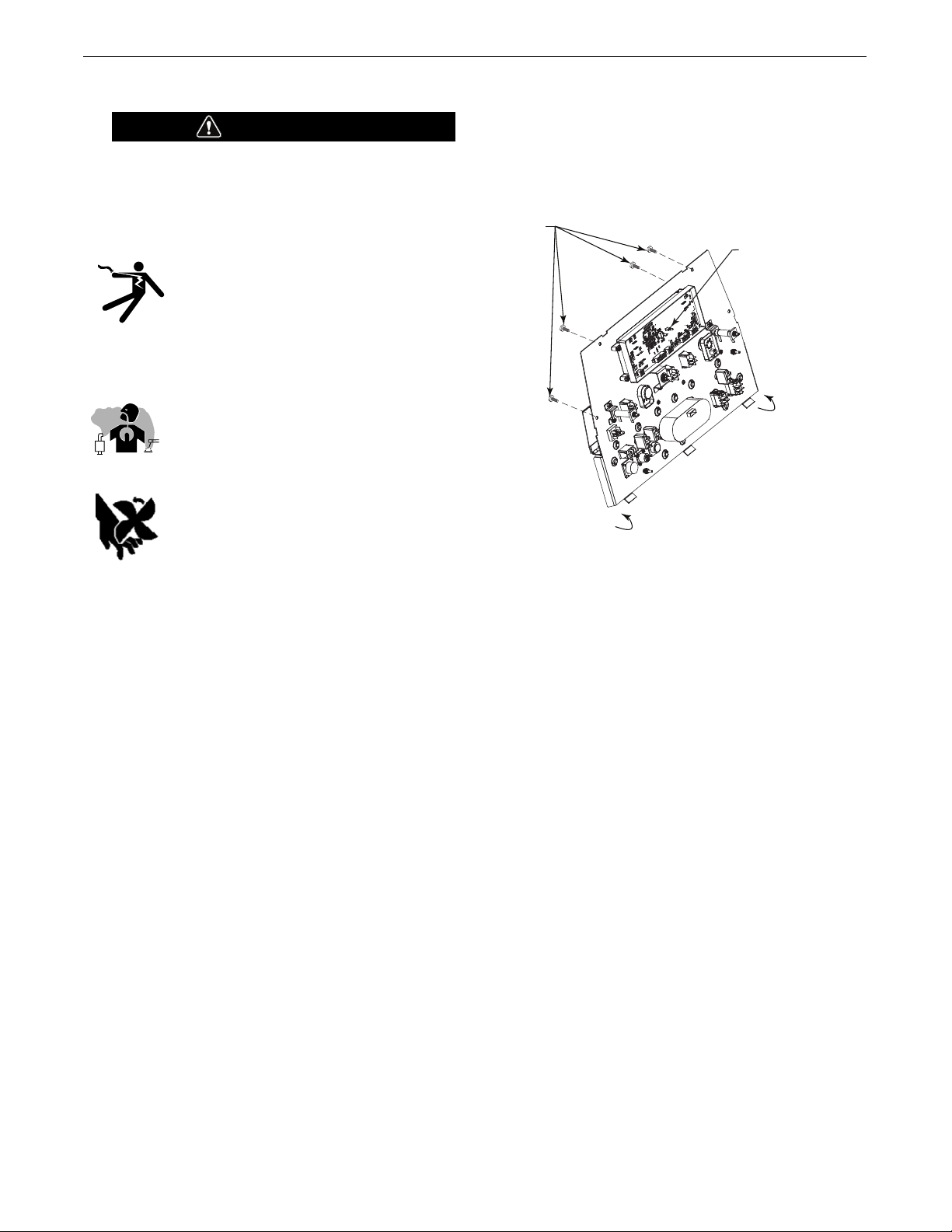
The machine is shipped with the VRD switch in the “OFF” position. To
turn it “On” or “Off”:
• Turn the engine “Off”.
• Disconnect the negative battery cable.
• Lower the Front panel by removing 4 side panel screws.
(See Figure
A.1)
• Place the VRD switch in the “On” or “Off” position. (See Figure A.1)
With the VRD switch in the “OFF” position, the VRD lights are deactivated.
FIGURE A.1
LOCATION AND VENTILATION
The welder should be located to provide an unrestricted flow of
clean, cool air to the cooling air inlets and to avoid restricting the
cooling air outlets. Also, locate the welder so that the engine
exhaust fumes are properly vented to an outside area.
DO NOT MOUNT OVER COMBUSTIBLE SURFACES
Where there is a combustible surface directly under stationary or fixed electrical equipment, that surface should be covered with a steel plate at least .06”(1.6mm) thick, which
should extend not less than 5.90”(150mm) beyond the equipment on all sides.
---------------------------------------------------------------------
STORING
1. Store the machine in a cool, dry place when it is not in use.
Protect it from dust and dirt. Keep it where it can’t be accidentally damaged from construction activities, moving vehicles,
and other hazards.
2. Drain the engine oil and refill with fresh oil. Run the engine for
about five minutes to circulate oil to all the parts. See the
ENGINE OPERATION section manual for details on changing oil.
3. Remove the battery, recharge it, and adjust the electrolyte
level. Store the battery in a dry, dark place.
STACKING
Vantage
®
435 machines cannot be stacked.
WARNING
REMOVE 4 FRONT
PANEL SCREWS
TO ACCESS (VRD)
SWITCH
ON / OFF VRD SWITCH
FRONT PANEL
ROTATES AWAY FROM
THE FRONT PART OF WELDER
A-3
INSTALLATION
VANTAGE®435
ANGLE OF OPERATION
To achieve optimum engine performance the Vantage®435
should be run in a level position. The maximum angle of operation
for the Deutz engine is 15 degrees in all directions. When operating
the welder at an angle, provisions must be made for checking and
maintaining the oil level at the normal (FULL) oil capacity. Also the
effective fuel capacity will be slightly less than the specified 20
gal.(75.7 ltrs.) will be slightly less than the amount specified.
LIFTING
The Vantage
®
435 weighs approximately 1641 lbs. (744kg.) with
a full tank of fuel and 1526 lbs. (692kg) less fuel. A lift bail is
mounted to the machine and should always be used when lifting
the machine.
• Lift only with equipment of adequate lifting capacity.
• Be sure machine is stable when lifting.
• Do not lift this machine using lift bale if it
is equipped with a heavy accessory such
as trailer or gas cylinder.
FALLING • Do not lift machine if lift bale is
EQUIPMENT can damaged.
cause injury. • Do not operate machine while
suspended from lift bale.
------------------------------------------------------------------
HIGH ALTITUDE OPERATION
At higher altitudes, output derating may be necessary. For maximum rating, derate the welder output in accordance with the guidelines in Table A.1 for this engine model from the manufacturer:
TABLE A.1 DEUTZ D 2.9 L4
ALTITUDE MAXIMUM POWER
METERS FEET AVAILABLE (%)
0-750 0-2461 99
1000 3281 95
2000 6562 95
3000 9842 93
4000 13123 88
5000 16404 74
6000 19685 60
HIGH TEMPERATURE OPERATION
At temperatures above 104°F (40°C), output voltage derating may
be necessary. For maximum output current ratings, derate welder
voltage rating 2 volts for every 21°F (10°C) above 104°F (40°C).
Cold weather starting:
With a fully charged battery and OW40 oil, the engine should
start satisfactorily down to -20°F (-29°C). If the engine must be
frequently started at or below 0°F (-18°C) cold starting aids are
recommended. At temperatures below 23°F (-5°C) fuels in
accordance with ASTM S975 Grade 1D diesel fuel is recommended. Allow the engine to idle for 3 to 5 minutes or until the
water temperature begins to rise before applying load to
switching to high idle.
Under no conditions should ether or other starting fluids be
used with this engine!
------------------------------------------------------------------
WARNING
WARNING

A-4
INSTALLATION
VANTAGE®435
TOWING
Use a recommended trailer for use with Vantage® 435 for road, inplant and yard towing by a vehicle(1). If the user adapts a non-Lincoln
trailer, they must assume responsibility that the method of
attachment and usage does not result in a safety hazard or damage
the welding equipment. Some of the factors to be considered are as
follows:
1. Design capacity of trailer vs. weight of Lincoln equipment and likely additional attachments.
2. Proper support of, and attachment to, the base of the welding equipment so
there will be no undue stress to the framework.
3. Proper placement of the equipment on the trailer to insure stability side to
side and front to back when being moved and when standing by itself while
being operated or serviced.
4. Typical conditions of use, i.e., travel speed; roughness of surface on which
the trailer will be operated; environmental conditions; like maintenance.
5. Conformance with federal, state and local laws.
(1)
(1)
Consult applicable federal, state and local laws regarding specific requirements for use on
public highways.
VEHICLE MOUNTING
Improperly mounted concentrated loads may cause unstable
vehicle handling and tires or other components to fail.
• Only transport VANTAGE® 435 on serviceable vehicles
which are rated and designed for such loads.
• Distribute, balance and secure loads so vehicle is stable
under conditions of use.
• Do not exceed maximum rated loads for components such
as suspension, axles and tires.
• Mount equipment base to metal bed or frame of vehicle.
• Follow vehicle manufacturer’s instructions.
------------------------------------------------------------------
PRE-OPERATION ENGINE SERVICE
READ the engine operating and maintenance instructions supplied
with this machine.
• Stop engine and allow to cool before fueling.
• Do not smoke when fueling.
• Fill fuel tank at a moderate rate and do not overfill.
• Wipe up spilled fuel and allow fumes to clear before starting engine.
• Keep sparks and flame away from tank.
------------------------------------------------------------------
OIL
The
Vantage®435
is shipped with the engine crankcase filled with high
quality SAE 10W-30 Oil that meets classification CJ-4 for diesel engines.
Check the oil level before starting the engine. If it is not up to the full mark on
the dip stick, add oil as required. Check the oil level every four hours of running time during the first 50 running hours. Refer to the engine Operator’s
Manual for specific oil recommendations and break-in information. The oil
change interval is dependent on the quality of the oil and the operating environment. Refer to the Engine Operator’s Manual for more details on the proper
service and maintenance intervals.
FUEL
USE DIESEL FUEL ONLY-
Ultra low sulphur fuel only.
• Fill the fuel tank with clean, fresh fuel. The capacity of the tank is
20 gallon (75.7 L). When the fuel gauge reads empty the tank contains approximately 2 gallon (7.6 L) of reserve fuel.
NOTE: A fuel shut off valve is located just before the pre-filter/sedi-
ment filter. Which should be in the closed position when the
welder is not used for extended periods of time.
------------------------------------------------------------------------
ENGINE COOLING SYSTEM
Air to cool the engine is drawn in the side and exhausted through
radiator and case back. It is important that the intake and exhaust
air is not restricted. Allow a minimum clearance of 1ft. (0.6m) from
the case back and 16 in. (406mm) from either side of the base to a
vertical surface.
------------------------------------------------------------------------
BATTERY CONNECTION
Use caution as the electrolyte is a strong acid that can burn skin and
damage eyes.
------------------------------------------------------------------------
The
Vantage®435
is shipped with the negative battery cable disconnected. Make certain that the RUN-STOP switch is in the STOP position.
Remove the two screws from the battery tray using a screwdriver or a
3/8"(10mm) socket. Attach the negative battery cable to the negative battery terminal and tighten using a 1/2"(13mm) socket or wrench.
NOTE: This machine is furnished with a wet charged battery; if
unused for several months, the battery may require a booster
charge. Be careful to charge the battery with the correct polarity.
(See Battery in “Maintenance Section”)
WARNING
WARNING
CAUTION
WARNING
A-5
INSTALLATION
VANTAGE®435
EXHAUST OUTLET PIPE
Remove cap from DPF outlet pipe protruding from roof.
Using the clamp provided secure the exhaust outlet pipe to the
outlet tube with the pipe positioned such that it will direct the
exhaust in the desired direction away from the air intake. Tighten
using a 1/2"(13mm) socket or wrench.
SPARK ARRESTOR
Some federal, state or local laws may require that gasoline or
diesel engines be equipped with exhaust spark arresters when
they are operated in certain locations where unarrested sparks
may present a fire hazard.
The Diesel Oxidation Catalyst (DOC) on this engine qualifies as a
spark arrestor that meets local regulations.
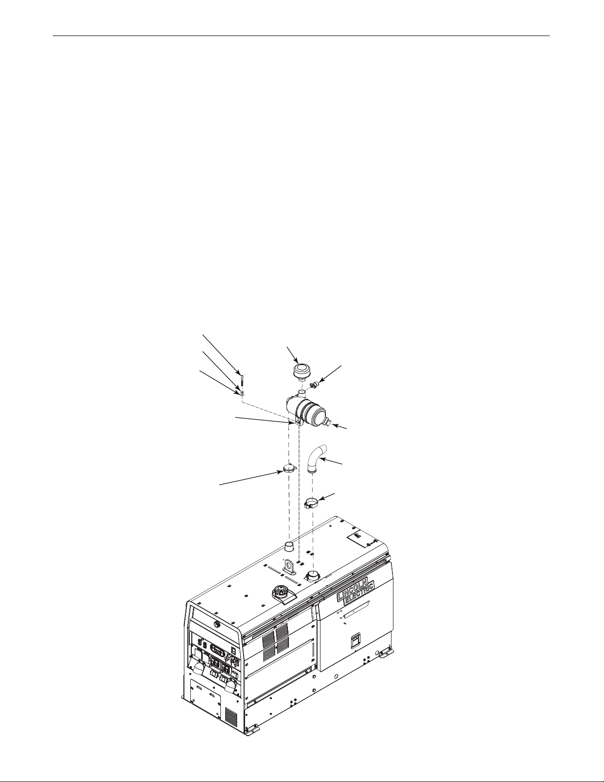
AIR CLEANER INSTALL
All parts below are shipped with the machine in a separate box
attached to the crate.(See Figure A.2)
• Remove cap from air intake hose.
• Tighten air hose clamp just below service indicator to hold
clamp while pushing air cleaner onto hose
(1)
, once hose is in
place loosen air hose clamp slide down and tighten clamp.
• Install 2 hex head screws, washers using a 1/2” (13mm)
wrench or socket to mounting bracket securing air cleaner.
• Unclip air cleaner end cap and rotate “TOP” text to be at
approximately 9 o’clock position.
• SERVICE INDICATOR
Air cleaner service indicator provides a Go/No-Go visual indication of useful filter service life.
(1)
Permissable to use a soap water solution as a lubricant to aid in hose
installation.
MOUNTING BRACKET
VACUATOR VALVE
INLET HOOD
EXHAUST OUTLET
CLAMP
(5/16-18x 1.25 HHCS) (2)
(LOCK WASHER) (2)
(MAIN WASHER) (2)
SERVICE INDICATOR
AIR HOSE CLAMP
FIGURE A.2
A-6
INSTALLATION
VANTAGE®435
REMOTE CONTROL
This Vantage®435 is equipped with a 12-pin and a 14-pin connector, along with a wireless remote control. To enable remote
control capabilities, the LOCAL/REMOTE switch must be in the
REMOTE position.
Only STICK mode output adjustment is controlled by the wireless
remote.
For the DOWNHILL PIPE or CC-STICK weld mode selector switch
positions, remote setting of the preset arc current is set through the 12
pin connector or the 14 pin connector depending on the setup menu
setting (12 pin connector is the factory default setting). The OUTPUT
CONTROL knob is used to set the maximum arc current preset range
for the remote input. The left display will show the arc current preset.
For the TOUCH START TIG weld mode selector switch position,
remote setting of the preset arc current is set through the 12 pin connector (typically using a foot Amptrol). The OUTPUT CONTROL knob is
used to set the maximum arc current preset range for the remote
input. The left display will show the maximum setting for the arc
current preset range as set by the OUTPUT CONTROL knob.
EXAMPLE: When the OUTPUT CONTROL on the welder is set to
200 amps, the arc current preset range on the remote control will
preset over the range from minimum to 200 amps, rather than the
full minimum to maximum preset arc current range. Any preset
arc current range that is less than the full range provides finer arc
current preset resolution for more fine tuning of the output.
For the ARC GOUGING weld mode selector switch position, remote setting of the preset arc current is set through the 12 pin connector. The
remote input sets the arc current preset over the full range from minimum to maximum. The left display will show the arc current preset.
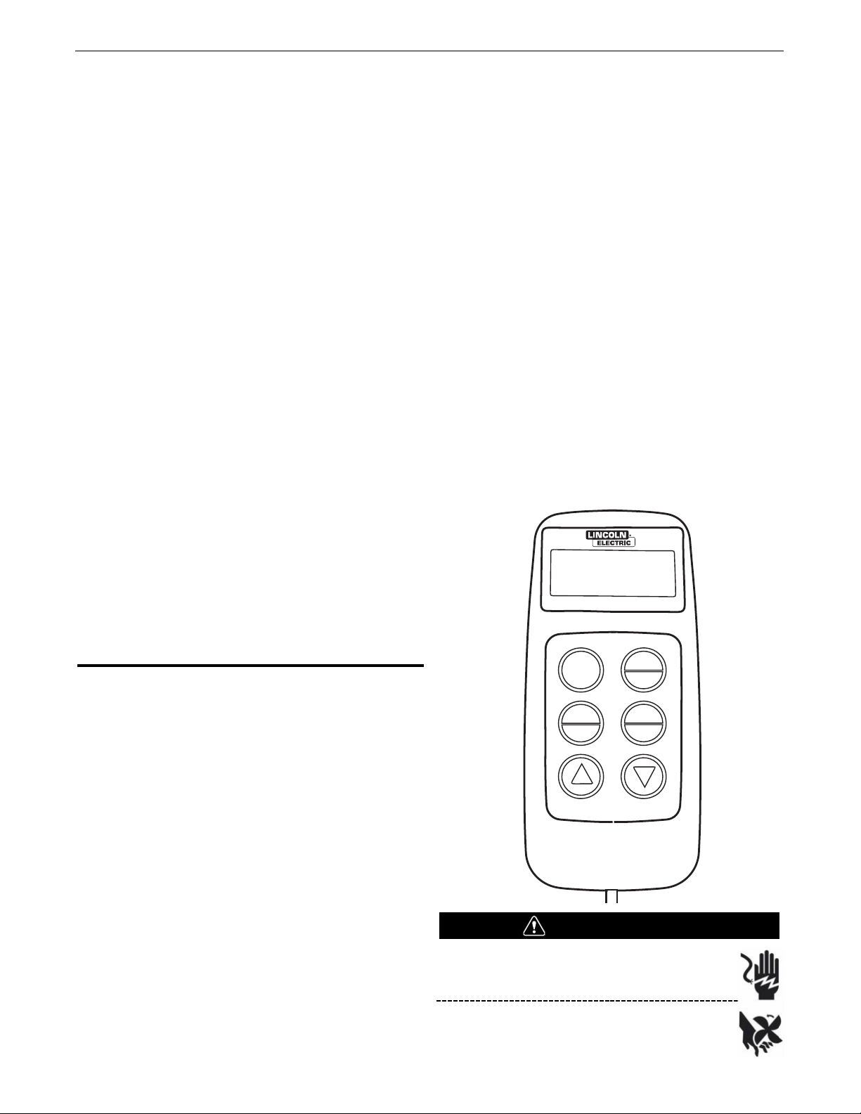
WIRELESS REMOTE CONTROL
Cold Starting Procedure
(See Figure B.3)
1. Toggle the ON/OFF toggle to the ON position to activate the
remote. The STOP/IDLE switch on the control panel needs to be
switched to the HIGH IDLE position to START the
Vantage®435
with the wireless remote.
The toggle switch on the receiver box is shipped from the factory
in the OFF position. If it is desired to operate the
Vantage®435
using the controls on the front panel and not the wireless
controls, leave the receiver toggle switch in the OFF position
2. Push the START/CI button once on the Transmitter. The greeting
screen will illuminate.
3. Push the START/CI button a second time. START will appear in
the upper left hand corner of the screen. The glow plugs are pre
heating . Wait 15 seconds for glow plugs to pre heat.
4. Push the START/CI button a third time to start the
Vantage®435
.
RUN will appear in the upper right hand side of the screen. The
Vantage®435
will start in the AUTO IDLE position and CI will
display on the screen. To go to HIGH IDLE, push the CO button
on the Transmitter. The STOP/IDLE switch on the control panel
will remain in the HIGH idle position when using the wireless
remote.
5. Push the increase button to test the increase function. Push the
decrease button to test the decrease function.
Warm Starting Procedure
(See Figure B.3)
1. Same as steps 1 and 2 from cold start procedure.
2. Push the START button on the transmitter a second time to
energize the Receiver and Transmitter. The word START will
appear in the upper right hand corner of the screen. Push
G.P./SEL button to terminate the glow plugs.
3. Same as step 4 and 5 from cold start procedure.
Shut Down Procedure
(See Figure B.3)
1. Push the STOP button on the Transmitter to shut the engine
down.
2. Push the STOP/IDLE switch on the control panel to the OFF
position.
Idle Control Operation
(See Figure B.3)
The unit will start and function in AUTO idle. To change the unit to
HIGH idle, press the CO button on the transmitter one time. To return
the unit to AUTO idle, press the CI button on the transmitter one time.
Output Adjustment
(See Figure B.3)
The output of the welder can be adjusted using the up and down
arrow buttons on the transmitter.
Only STICK mode output adjustment is controlled by the wireless
remote.
FIGURE B.3
This equipment is capable of remote starting and
may start without warning if activated.
Always disconnect battery and turn the Receiver
Box Toggle Switch to the “Off” position before
servicing this equipment.
OUTPUT 2
STOP
START
CI
G P
SEL
IDLE
C O
—
+
AMPS
WARNING

A-7
INSTALLATION
VANTAGE®435
For operation with a control cable wire feeder:
With the CV-WIRE weld mode selector switch position and the
WELD TERMINALS ON switch in the REMOTE position, remote
setting of the preset arc voltage is set through the 14 pin connector. The remote input sets the arc voltage preset range from
10.0V to 45.0V. The right display will show the arc voltage preset.
For operation with an across the arc wire feeder (for example,
an LN-25 PRO):
With the CV-WIRE weld mode selector switch position and the
WELD TERMINALS ON switch in the ON position, remote setting
of the preset arc voltage is set through the 12 pin connector. The
remote input sets the arc voltage preset range from 10.0V to
45.0V. The right display will show the arc voltage preset.
For the ARCLINK weld mode selector switch position, remote
capability is possible only with an ArcLink compatible digital
remote control through the 12 pin connector.
NOTE: To connect accessories with a 6 pin connector, use the
included 12-pin to 6-pin adaptor (K2909-1).
-----------------------------------------------------------------
WELDING TERMINALS
The
Vantage®435
is equipped with a toggle switch for selecting "hot"
welding terminals when in the "WELD TERMINALS ON" position or "cold"
welding terminals when in the "REMOTELY CONTROLLED" position. When in
ArcLink, the output of the weld terminals is controlled by the mode selected.
WELDING OUTPUT CABLES
With the engine off, route the electrode and work cables through the
strain relief bracket provided on the front of the base and connect to the
terminals provided. These connections should be checked periodically
and tightened if necessary.
Listed in Table A.2 are copper cable sizes recommended for the rated current and duty cycle. Lengths stipulated are the distance from the welder to
work and back to the welder again. Cable sizes are increased for greater
lengths primarily for the purpose of minimizing cable voltage drop.
TABLE A.2
PULSE WELDING
W
hen pulse welding, always use 4/0 cable. The cables must be sized
based upon the peak current of the pulse waveform, not the average
current. Do not coil the electrode or work cable. Limit the combined
length of the electrode and work cable to 60 feet. Undersized cables,
coiled cables and long lengths all increase cable inductance and
lower pulse welding performance.
CABLE INSTALLATION
Install the welding cables to your
VANTAGE®520 SD
as follows.
1. The engine must be OFF to install welding cables.
2. Remove the flanged nuts from the output terminals.
3. Connect the electrode holder and work cables to the weld output terminals.
The terminals are identified on the case front.
4. Tighten the flanged nuts securely.
5. Be certain that the metal piece you are welding (the “work”) is properly
connected to the work clamp and cable.
6. Check and tighten the connections periodically.
• Loose connections will cause the output terminals to over-
heat. The terminals may eventually melt.
• Do not cross the welding cables at the output terminal con-
nection. Keep the cables isolated and separate from one
another.
------------------------------------------------------------------
CAUTION
OUTPUT CABLE GUIDELINES
Percent Duty
Amperes
200
200
250
250
250
250
300
300
350
400
400
500
600
600
600
** Tabled values are for operation at ambient temperatures of 104°F (40°C) and below. Applications above
104°F (40°C) may require cables larger than recommended, or cables rated higher than 167°F (75°C).
CABLE SIZES FOR COMBINED LENGTHS OF ELECTRODE AND WORK
CABLES [RUBBER COVERED COPPER - RATED 167°F (75°C)]**
Cycle
0 to 50 Ft. 50 to 100 Ft. 100 to 150 Ft. 150 to 200 Ft. 200 to 250 Ft.
60
100
30
40
60
100
60
100
40
60
100
60
60
80
100
2/0
1/0
2/0
3/0
2/0
3/0
2-1/0
2-1/0
2
2
3
2
1
1
1
2
2
3
2
1
1
1
2/0
1/0
2/0
3/0
2/0
3/0
2-1/0
2-1/0
2
2
2
1
1
1
1
2/0
2/0
2/0
3/0
3/0
3/0
2-1/0
2-1/0
2-2/0
2-2/0
1
1
1
1
1
1
1/0
2/0
2/0
3/0
3/0
3/0
4/0
1/0
1/0
1/0
1/0
1/0
1/0
2/0
3/0
3/0
4/0
4/0
4/0
2-3/0
2-3/0
2-3/0
A-8
INSTALLATION
VANTAGE®435
MACHINE GROUNDING
Because this portable engine driven welder creates its own power, it is
not necessary to connect its frame to an earth ground, unless the
machine is connected to premises wiring (home, shop, etc.).
To prevent dangerous electric shock, other equipment powered by this
engine driven welder must:
a) be grounded to the frame of the welder using a grounded type
plug, or
b) be double insulated.
When this welder is mounted on a truck or trailer, its frame must be securely
connected to the metal frame of the vehicle. When this engine driven welder is
connected to premises wiring such as that in a home or shop, its frame must
be connected to the system earth ground. See further connection instructions
in the section entitled “Standby Power Connections” as well as the article on
grounding in the latest National Electrical Code and the local codes.
In general, if the machine is to be grounded, it should be connected
with a #8 or larger copper wire to a solid earth ground such as a metal
ground stake going into the ground for at least 10Ft.(3.1m) or to the
metal framework of a building which has been effectively grounded.
The National Electric Code lists a number of alternate means of
grounding electrical equipment. A machine grounding stud marked
with the symbol is provided on the front of the welder.
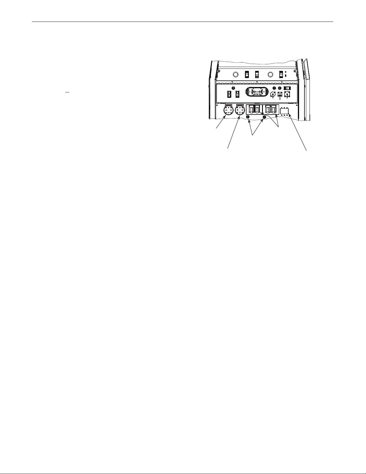
AUXILIARY POWER RECEPTACLES
Start the engine and set the “IDLE/RUN/STOP” switch to the “High
Idle” mode. Voltage is now correct at the receptacles for auxiliary
power. This must be done before a tripped GFCI can be reset properly.
See the MAINTENANCE section for more detailed information on testing and resetting the GFCI. (For location of receptacles see Figure A.3)
The auxiliary power of the
Vantage®435 consists of two 20 Amp-
120 VAC (5-20R) duplex receptacles with GFCI protection, one 50
Amp 120/240 VAC (14-50R) receptacle and one 50 Amp 240VAC
Three-Phase (15-50R) receptacle.
The auxiliary power capacity is 11,000 Watts Continuous of 60 Hz,
single phase power. The auxiliary power capacity rating in watts is
equivalent to volt-amperes at unity power factor. The max permissible
current of the 240 VAC output is 50amps.
The 240 VAC output can be split to provide two separate 120 VAC outputs with a max permissible current of 50 Amps per output to two separate 120 VAC branch circuits (these circuits cannot be paralleled).
Output voltage is within ± 10% at all loads up to rated capacity.
The Three-Phases auxiliary power capacity is 17,000 watts continuous. The maximum current is 40 amps.
FIGURE A.3
120 V DUPLEX RECEPTACLES AND GFCI
A GFCI protects the two 120V auxiliary power receptacles.
A GFCI (Ground Fault Circuit Interrupter) is a device to protect against
electric shock should a piece of defective equipment connected to it
develop a ground fault. If this situation should occur, the GFCI will trip,
removing voltage from the output of the receptacle. If a GFCI is tripped
see the MAINTENANCE section for detailed information on testing and
resetting it. A GFCI should be properly tested at least once every month.
The 120 V auxiliary power receptacles should only be used with three
wire grounded type plugs or approved double insulated tools with two
wire plugs. The current rating of any plug used with the system must
be at least equal to the current capacity of the associated receptacle.
NOTE: The 240 V receptacle has two 120 V circuits, but are of opposite polarities and cannot be paralleled.
All auxiliary power is protected by circuit breakers. The 120V has 20 Amp
circuit breakers for each duplex receptacle. The 120/240V Single Phase
and the 240V Three-Phases have a 50 Amp 3-pole Circuit Breaker that
disconnects both hot leads and all Three Phases simultaneously.
AUXILIARY POWER RECEPTACLES
240 VAC THREE
PHASE RECEPTACLE
120/240 VAC SINGLE
PHASE RECEPTACLE
120 V RECEPTACLE
20A 120V
AUXILIARY BREAKERS
50A 240V THREE
POLE BREAKER
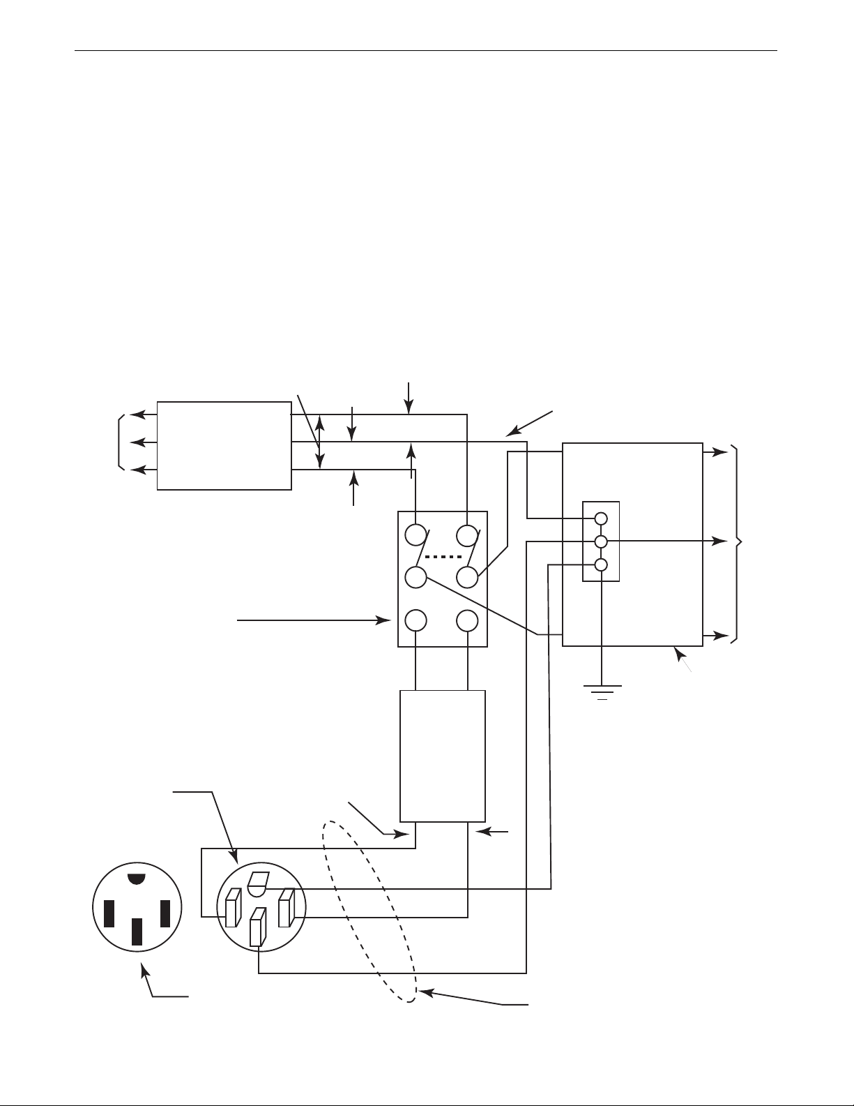
FIGURE A.4 Connection of the VANTAGE®435 to Premises Wiring
A-9
INSTALLATION
VANTAGE®435
STANDBY POWER CONNECTIONS
The Vantage®435 is suitable for temporary, standby or emergency power using the engine manufacturer’s recommended
maintenance schedule.
The Vantage
®
435 can be permanently installed as a standby
power unit for 240 volt-3 wire, 50 amp service. Connections must
be made by a licensed electrician who can determine how the
120/240 VAC power can be adapted to the particular installation
and comply with all applicable electrical codes. Refer to the connection diagram shown in Figure A.4.
1. Install the double-pole, double-throw switch between the power
company meter and the premises disconnect. Switch rating
must be the same or greater than the customer’s premises disconnect and service over current protection.
2. Take necessary steps to assure load is limited to the capacity of
the Vantage
®
435 by installing a 50 amp, 240 VAC double pole
circuit breaker. Maximum rated load for each leg of the 240
VAC auxiliary is 50 amps. Loading above the rated output will
reduce output voltage below the allowable -10% of rated voltage which may damage appliances or other motor-driven
equipment and may result in overheating of the Vantage
®
435
engine and / or alternate windings.
3. Install a 50 amp 120/240 VAC plug (NEMA Type 14-50P) to the
double-pole circuit breaker using No. 6, 4 conductor cable of
the desired length.
4. Plug this cable into the 50 Amp 120/240 Volt receptacle on the
Vantage
®
435 case front.
240 VOLT
240 Volt
60 Hz.
3-Wire
Service
POWER
COMPANY
METER
120 VOLT
120 VOLT
GROUNDED CONDUCTOR
DOUBLE POLE DOUBLE THROW
SWITCH RATING TO BE THE SAME
AS OR GREATER THAN PREMISES
SERVICE OVERCURRENT
PROTECTION.
50 AMP, 120/240
VOLT PLUG
NEMA TYPE 14-50
240 VOLT
50AMP
240 VOLT
DOUBLE
POLE
CIRCUIT
BREAKER
GND
GROUND
NEUTRAL
BUS
N
PREMISES
DISCONNECT AND
SERVICE
OVERCURRENT
PROTECTION
LOAD
50 AMP, 120/240 VOLT
RECEPTACLE
N
NOTE: No. 6 COPPER CONDUCTOR CABLE SEE
NATIONAL ELECTRICAL CODE FOR ALTERNATE WIRE
SIZE RECOMMENDATIONS.
A-10
INSTALLATION
VANTAGE®435
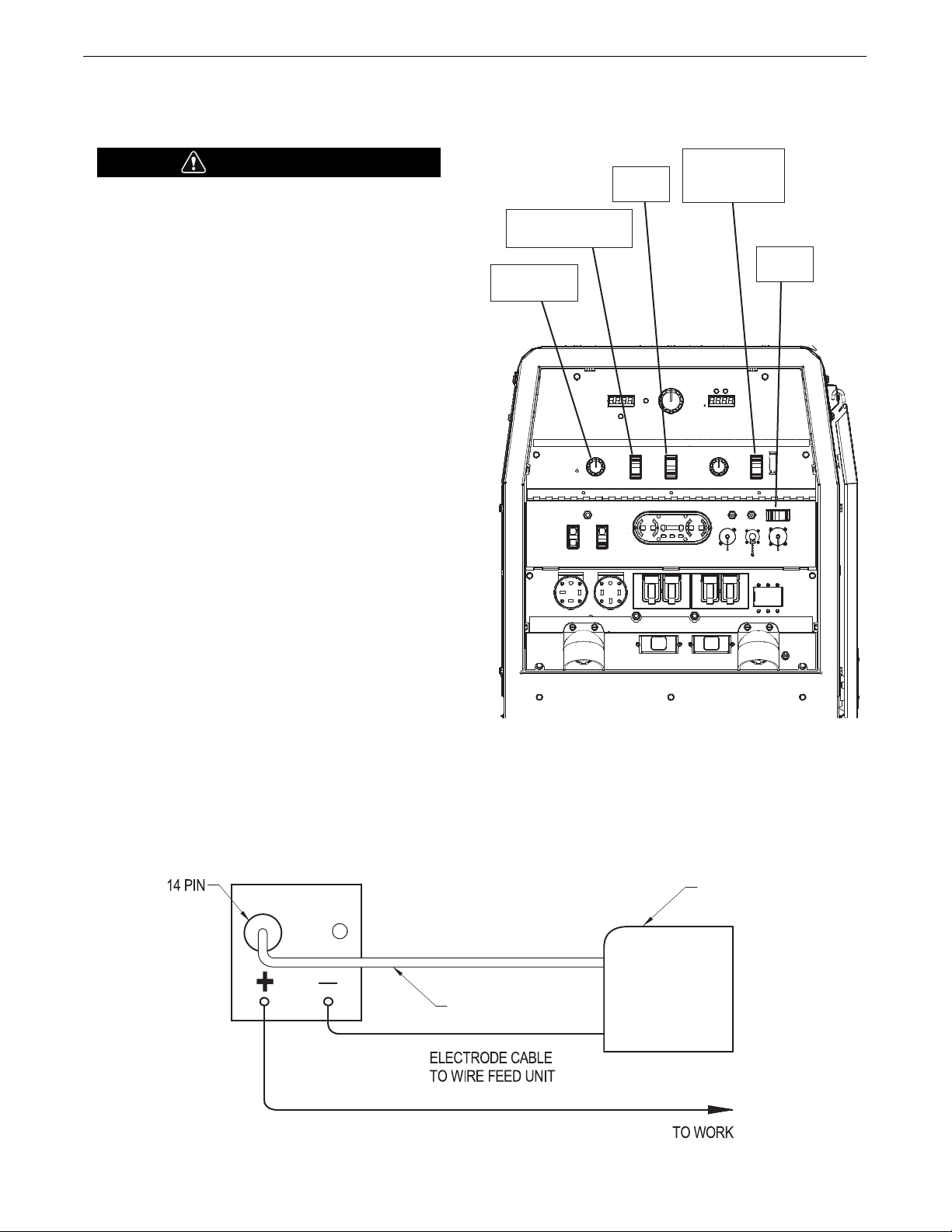
CONNECTION OF WIRE FEEDERS WITH CONTROL
CABLE (14 PIN)
Shut off welder before making any electrical connections.
------------------------------------------------------------------
CONNECTION OF LF-72, LF-74, FLEX FEED 74 HT,
FLEX FEED 84, LN-25 PRO DUAL POWER TO THE
VANTAGE
®
435
• Shut the welder off.
• Set the “WIRE FEEDER VOLTMETER” switch to either “+” or “-”
as required by the electrode being used (See Figure A.5).
• For electrode Positive, connect the electrode cable to the "+" terminal of the welder and work cable to the "-" terminal of the welder.
For electrode Negative, connect the electrode cable "-" terminal of
the welder and work cable to the "+" terminal of the welder.
• Set the “MODE” switch to the “CV-WIRE” position.
• Adjust the “ARC CONTROL” knob to desired Crispness. SOFT for
MIG and CRISP for Innershield.
• Set the “WELDING TERMINALS” switch to the “REMOTELY
CONTROLLED” position.
• Set the wire feeder voltage switch to 42V.
• Connect the 14 pin control cable from the wire feeder to the
engine drive (See Figure A.6).
• Set the “REMOTE/LOCAL” switch to “REMOTE” if the feeder is
equipped with a remote output control knob.
WARNING
Set Polarity to
match electrode
polarity
Set to
Remote
Set weld terminals to
remotely controlled
Set mode to
CV Wire
Set to
42V
FIGURE A.6
FIGURE A.5
ENGINE WELDER
WIRE FEEDER
K1797-xx
CABLE
 Loading...