

Page 1

SERVICE MANUAL
(DOMESTIC & INTERNATIONAL)
IMPINGER X2 OVENS
WITH ANALOG CONTROLS
MODEL
3240-2, 3262-2, 3270-2
Lincoln Foodservice Products, Inc.
1111 North Hadley Road
P.O. Box 1229
Fort Wayne, Indiana 46801-1229
Phone: (800) 374-3004 • Fax: (260) 436-0735
Technical Service Hot Line
(800) 678-9511
www.lincolnfp.com
X2svcmanual REV: 12/7/05
Page 2

SEQUENCE OF OPERATION
IMPINGER X2 OVENS
3240-2* 120/230VAC 60 HZ. 1 PHASE
3240-2* 120/230VAC 60 HZ. 3 PHASE
3262-2* 120/230VAC 60 HZ. 1 PHASE
3262-2* 120/230VAC 60 HZ. 3 PHASE
3270-2* 120/230VAC 60 HZ. 1 PHASE
3270-2* 120/230VAC 60 HZ. 3 PHASE
*NOTE:
Model number ending in TS indicates top belt is split belt
Model number ending in SB indicates bottom belt is split belt
Model number ending in SS indicates both belts are split belts
POWER SUPPLY Electrical power to be supplied to the oven by a four conductor service for single phase
or a five conductor service for three phase.
Black conductor is hot.
Red conductor is hot.
Orange conductor is hot.
White conductor is neutral.
Green conductor is ground.
MAIN FAN CIRCUIT Power is permanently supplied to the normally open contacts of the main fan relay.
Power is also supplied, through a 2 amp. fuse, to the 30 minute time delay relay.
Closing the oven fan switch enables the 30 minute time delay relay. The 30 minute time
delay relay supplies 120VAC to the coil of the main fan relay. These normally open
contacts now close energizing the main fan motor. Closing the main fan switch also
supplies 120VAC to the burner and conveyor switches.
BURNER CIRCUIT Closing the main fan switch supplies 120VAC to the normally open burner switch.
Closing the burner switch supplies 120VAC to the electronic temperature control,
through the air pressure switch and the oven cavity hi-limit thermostat, to the normally
open contact of the burner blower relay and to the primary of the burner transformer.
The transformer’s secondary supplies 24VAC To the normally open contacts of the
burner blower motor centrifugal switch and to the coil of the burner blower relay (the
normally open contacts close within 30 seconds). The burner blower relay contacts
close, supplying 120VAC to the burner blower motor. As the burner blower motor
reaches operating speed, it’s internal centrifugal switch closes, supplying 24VAC to the
burner control. When the burner control is supplied with 24VAC, the pilot valve is
energized and the igniter circuit is energized. Ignition should now occur. After the pilot
flame is proven, the main gas valve is energized.
TEMPERATURE CONTROL Closing the main fan switch and burner switch supplies 120VAC to the electronic
temperature control. The electronic temperature control is adjusted to the desired
temperature. The thermocouple will provide varying millivolts to the electronic
temperature control. The temperature control supplies 120VAC to the temperature
regulation valve at intermittent intervals to maintain desired temperature.
CONVEYOR DRIVE
THE OVEN WILL CONTAIN BETWEEN TWO AND FOUR SEPARATE CONVEYOR
DRIVE SYSTEMS. THE SEQUENCE OF OPERATIONS WILL BE THE SAME FOR
EACH MOTOR SYSTEM.
Closing the main fan switch and the normally open conveyor switch supplies 120VAC,
through a 2 Amp. fuse, to the conveyor control. AC voltage is converted to DC voltage
and DC voltage is supplied, at terminals A+ and A-, to the conveyor motor. Adjusting the
conveyor control will vary the DC output voltage. The speed of the motor will increase or
decrease as the DC voltage from the conveyor control increases or decreases.
NOTE:
AUTOMATIC COOL DOWN When the oven is started, the 30 minute time delay relay is enabled, permitting the oven
The conveyor control uses a hall effect sensor and magnet, mounted on the conveyor
motor that senses motor speed. Any change in motor load (± RPM) is detected by the
sensor and the voltage to the motor is adjusted accordingly.
fan to operate for approximately 30 minutes after the oven is shut off, to cool the oven.
When the oven is shut off, the 30 minute time delay relay will keep the coil of the main
fan relay closed for 30 minutes, maintaining operation of the main fan motor.
Impinger X2 – Analog Service Manual – Dom & Int’l2
Page 3

SEQUENCE OF OPERATION
IMPINGER X2 OVENS
3240-2* 230VAC 50 HZ. 1 PHASE
3262-2* 230VAC 50 HZ. 1 PHASE
3270-2* 230VAC 50 HZ. 1 PHASE
*NOTE:
Model number ending in TS indicates top belt is split belt
Model number ending in SB indicates bottom belt is split belt
Model number ending in SS indicates both belts are split belts
POWER SUPPLY Electrical power to be supplied to the oven by a three conductor service for single phase
or a five conductor service for three phase.
Black conductor is hot.
Red conductor is hot.
Orange conductor is hot.
White conductor is neutral.
Green conductor is ground.
MAIN FAN CIRCUIT Power is permanently supplied to the normally open contacts of the main fan relay.
Power is also supplied, through a 2 amp. fuse, to the 30 minute time delay relay.
Closing the oven fan switch enables the 30 minute time delay relay. The 30 minute time
delay relay supplies 220/240VAC to the coil of the main fan relay. These normally open
contacts now close energizing the main fan motor. Closing the main fan switch also
supplies 220/240VAC to the burner and conveyor switches.
BURNER CIRCUIT Closing the main fan switch supplies 220/240VAC to the normally open burner switch.
Closing the burner switch supplies 220/240VAC, through the EMI filter, to the electronic
temperature control. 220/240VAC is supplied, through the air pressure switch and the
oven cavity hi-limit thermostat, to the burner control. When the burner control is
energized, 220/240VAC is supplied to the burner blower motor. The normally open air
pressure switch closes upon sensing air pressure. After a pre-purge of 30 seconds, the
pilot valve and spark are energized. Ignition should now occur. After the pilot flame is
proven, the main valve is energized.
TEMPERATURE CONTROL Closing the main fan switch and burner switch supplies 220/240VAC to the electronic
temperature control. The electronic temperature control is adjusted to the desired
temperature. The thermocouple will provide varying millivolts to the electronic
temperature control. The temperature control supplies 220/240VAC to the temperature
regulation valve at intermittent intervals to maintain desired temperature.
CONVEYOR DRIVE
THE OVEN WILL CONTAIN BETWEEN TWO AND FOUR SEPARATE CONVEYOR
DRIVE SYSTEMS. THE SEQUENCE OF OPERATIONS WILL BE THE SAME FOR
EACH MOTOR SYSTEM.
Closing the main fan switch supplies 220/240VAC, through the EMI filter, to the normally
open conveyor switch, through a 2 Amp. fuse, to the conveyor control. AC voltage is
converted to DC voltage and DC voltage is supplied, at terminals A+ and A-, to the
conveyor motor. Adjusting the conveyor control will vary the DC output voltage. The
speed of the motor will increase or decrease as the DC voltage from the conveyor
control increases or decreases.
NOTE:
AUTOMATIC COOL DOWN When the oven is started, the 30 minute time delay relay is enabled, permitting the oven
Impinger X2 – Analog Service Manual – Dom & Int’l 3
The conveyor control uses a hall effect sensor and magnet, mounted on the conveyor
motor that senses motor speed. The sensor detects any change in motor load (± RPM)
and the voltage to the motor is adjusted accordingly.
fan to operate for approximately 30 minutes after the oven is shut off, to cool the oven.
When the oven is shut off, the 30 minute time delay relay will keep the coil of the main
fan relay closed for 30 minutes, maintaining operation of the main fan motor.
Page 4
SCHEMATIC DIAGRAM
MODEL 3240-2, 3262-2, 3270-2 60 HZ.
Impinger X2 – Analog Service Manual – Dom & Int’l4
Page 5
SCHEMATIC DIAGRAM
MODEL 3240-2, 3262-2, 3270-2 50 HZ.
Impinger X2 – Analog Service Manual – Dom & Int’l 5
Page 6

TROUBLESHOOTING GUIDE
3240-2* 120/230VAC 60 HZ. 1 PHASE
3240-2* 120/230VAC 60 HZ. 3 PHASE
3262-2* 120/230VAC 60 HZ. 1 PHASE
3262-2* 120/230VAC 60 HZ. 3 PHASE
3270-2* 120/230VAC 60 HZ. 1 PHASE
3270-2* 120/230VAC 60 HZ. 3 PHASE
*NOTE:
Model number ending in TS indicates top belt is split belt
Model number ending in SB indicates bottom belt is split belt
Model number ending in SS indicates both belts are split belts
SYMPTOM POSSIBLE CAUSE EVALUATION
Oven fan will not run Incoming power supply Check circuit breakers. Reset if required. Call power
co. if needed.
Fuse, 2 Amp, control (F7) Check, replace if necessary.
Fuse holder Check, replace if necessary.
Switch, oven fan Check continuity between switch terminals. Replace
switch as needed.
30 minute time delay relay Check for supply voltage to 30 minute time delay relay
at terminals #2 and #3. If no voltage is present, trace
wiring back to main power switch. If there is supply
voltage at terminals #2 and #3, check for output voltage
at terminals #1 and #3. If there is incoming voltage but
no output voltage, and the main power switch is on,
replace the 30 minute time delay relay.
Relay, main fan Check for supply voltage to relay contacts, if no voltage
is present, trace wiring back to power supply. Check for
120VAC to the coil of the main fan relay. If no voltage is
present, trace wiring back to the 30 minute time delay
relay, check to be sure that the Overload Protector
contacts are closed. If contacts are open, see
“Overload Protector” below. If voltage is present, check
to insure relay contacts are closing. Replace relay as
needed.
Overload protector, main fan Check to be sure overload contacts are closed. If not
closed, re-set overload. If contacts do not close,
replace overload protector. If contacts close, test for
proper operation. If the overload contacts do not stay
closed, and the amperage is below the overload
setting, replace the overload protector.
3240 should be set at 13A
3260 should be set at 18A
3270 should be set at 18A
Main fan motor Check for supply voltage at motor. If no voltage is
present, trace wiring back to the overload protector.
WITH POWER OFF: Check for opens, shorts or
grounds. Turn motor shaft to check for locked rotor.
Capacitor Check for shorts or grounds.
WARNING: Capacitor has a stored charge, discharge
before testing.
Drive belt Check for loose or broken drive belt. Adjust motor for
proper belt tension (maximum of 3/8-inch deflection), or
replace drive belt as needed.
Bearings, Fan shaft Check for any damage or excessive wear on the shaft
Impinger X2 – Analog Service Manual – Dom & Int’l6
Page 7

bearings. Replace bearings as needed.
Oven will not heat Gas supply Check for adequate gas supply to oven.
Manual gas shut off valve Check to see that the manual gas shut off valve is
open. Also, check flexible gas line connection for any
damage.
Main fan motor Check for main fan operation. If it is not operating, refer
to “Oven fan will not run”.
Relay, main fan Check for 120VAC supplied to relay terminal #13. If
voltage is not present, trace wiring back to power
supply. If voltage is present, check for 120VAC at
terminal #14. If there is no voltage at terminal #14, and
the relay is energized, replace the main fan relay.
Fuse, 2 Amp, control (F8) Check, replace if necessary.
Fuse holder Check, replace if necessary.
Switch, oven fan Check for 120VAC to the switch, if no voltage is
present, trace wiring back to the main fan relay. Check
continuity between switch terminals. Replace switch as
needed.
Switch, burner Check for 120VAC to the switch, if no voltage is
present, trace wiring back to the oven fan switch.
Check continuity between switch terminals. Replace
switch as needed.
Air pressure switch Check for 120VAC to the air pressure switch. If no
voltage is present, trace wiring back to burner switch.
This normally open switch should close when the main
fan is activated. Check air switch tube for blockage or
any obstructions, repair as needed. Refer to the
“Removal and installation” section for proper
adjustment of air pressure switch. Replace air pressure
switch as needed.
Transformer, burner Check for 120VAC supplied to primary of transformer. If
no voltage is present, trace wiring back to the air
pressure switch. If voltage is present, check for 24VAC
at transformer secondary. If there is primary voltage but
no secondary voltage, replace burner transformer.
Relay, burner blower Check for 24VAC supply to relay coil. If no voltage is
present, trace wiring back to burner transformer. Check
for 120VAC to relay contact. If no voltage is present,
trace wiring back to air pressure switch. When 24VAC
is applied to the coil, there will be a delay of 20 – 30
seconds. After this time delay, the relay contacts
should close. If there is 24VAC applied, but the
contacts do not close, replace the burner blower relay.
Motor, burner blower Check for 120VAC supplied to the burner blower motor.
If no voltage is present, trace wiring back to the burner
blower relay. If voltage is present, and the motor is not
turning, check for opens, shorts or grounds.
WITH POWER OFF: Check for locked rotor.
Replace burner blower motor as needed.
Centrifugal switch of
Burner blower motor
Check for 24VAC supplied to centrifugal switch at wire
S5. If no voltage is present, trace wiring back to the
burner transformer. If voltage is present, check for
24VAC out of centrifugal switch at wire #32. If there is
voltage in, but there is no voltage out, and the burner
blower motor is running, replace the burner blower
motor.
Burner control Check for 24VAC supplied to the burner control at
terminals #5 and #6. If no voltage is present, trace
Impinger X2 – Analog Service Manual – Dom & Int’l 7
Page 8

Pilot valve Check for 24VAC supplied to pilot valve. If no voltage is
No pilot flame If the ignition control is supplied with 24VAC and the
Pilot tube Check for gas pressure at the pilot tube. Disconnect
Pilot orifice If there is gas pressure at the pilot tube, check the pilot
Burner igniter Check the burner igniter head for any damage or
NOTE: Flame should be
On at this time
Pilot flame, but no main flame Electronic temperature
control
Thermocouple probe WITH POWER ON AND THERMOCOUPLE LEADS
Burner control. Check for 24VAC supplied to main valve. If no voltage
Main gas valve Check to see that the switch on the valve is in the “ON”
wiring back to the centrifugal switch of the burner
blower motor. If voltage is present, check for 24VAC at
pins #3 and #2 (pilot valve). If voltage is not present,
replace burner control. If the pilot valve is energized,
check to see that the high voltage igniter circuit is also
energized. To check, turn power off, disconnect the
igniter lead from the ignition control. Turn power on. If
no spark is visible, replace burner control. If a spark is
visible at burner control, proceed.
present, trace wiring back to burner control. If voltage is
present, check for gas pressure at the pilot line
connection. If no gas pressure is present during
ignition, check for any blockage in the assembly. If
there are no obstructions, and there is gas supplied to
the oven, replace the gas valve.
pilot valve and igniter circuits are energized, visually
check for a pilot flame. This may be done by looking
through the inspection view port on the end of the
burner. If no pilot flame is visible, check the pilot tube.
pilot tube at the burner And connect manometer to pilot
tube. If no gas pressure is present during ignition,
check for blockage of the pilot tube. If the pilot tube is
clear, proceed.
orifice for blockage or obstructions. Replace pilot orifice
as needed.
obstructions also check for frayed or broken wire.
Check spark gap, gap should be 3/32” If there is visible
damage, replace burner igniter.
Check for 120VAC supplied to electronic temperature
control at terminals #13 and #12. Of there is no voltage,
trace wiring back to the burner switch. Also check for
120VAC supplied to terminal #20 on the electronic
temperature control. If there is no voltage at terminal
#20, trace wiring back to terminal #13. Set temperature
control to maximum temperature and check for
120VAC output at terminal #21 and neutral. If 120VAC
is present at terminal #20 and neutral, and the unit is
not heating, refer to “Temperature regulation valve” for
next check. If 120 VAC is not present, proceed.
ATTACHED TO THE ELECTRONIC TEMPERATURE
CONTROL: Measure the D.C. millivolt output of these
leads. Refer to chart in the “Removal, Installation and
Adjustment” section for proper readings. If these
readings are not achieved, replace thermocouple.
is present, trace wiring back to burner control. If there is
no voltage output, replace burner control.
position. Check for 24VAC supplied to main valve. If
there is voltage present, check to see that valve is
opening. Connect manometer to pressure tap on outlet
side of valve. If there is voltage to the valve, but no
output gas pressure, replace the valve.
Impinger X2 – Analog Service Manual – Dom & Int’l8
Page 9

Temperature regulation valve If 120VAC is present on the electronic temperature
control, terminal #13 to neutral, check for voltage at
temperature regulation valve. If no voltage is present,
trace wiring back to electronic temperature control. If
voltage is present, listen for valve to open and close.
Also check for opens or shorts in the operating coil.
Replace temperature regulation valve as needed.
Intermittent heating Thermal/Overload of main fan
and burner blower motors
The main fan motor and burner blower motor are
equipped with internal thermal protection and will cease
to operate if overheating occurs. As the motors over-
heat and then cool, this will cause the units to cycle on
and off intermittently. Improper ventilation or lack of
preventive maintenance may cause this. Also, most of
the problems listed under “Oven will not heat” can
cause intermittent failure.
Conveyor will not run NOTE: The ovens may contain two, three or four conveyor drive systems using like
components. The trouble shooting sequence will be the same for each of the conveyor
drive systems
Power supply Check circuit breakers, reset if required. Check power
plug to be sure it is firmly in receptacle. Measure
incoming power, call power co. if needed.
Switch, oven fan Check continuity between switch terminals. Replace
switch as needed.
Relay, main fan Check for 120VAC supplied to relay terminal #13. If
voltage is not present, trace wiring back to power
supply. If voltage is present, check for 120VAC at
terminal #14. If there is no voltage at terminal #14, and
the relay is energized, replace the main fan relay.
Fuse, 2 Amp Check, replace if necessary.
Fuse holder Check for 120VAC supplied to fuse holder. If no voltage
is present, trace wiring back to main fan relay. Check
fuse holder, replace if necessary.
Switch, conveyor Check for 120VAC supplied to conveyor switch. If no
voltage is present, trace wiring back to fuse holder.
Check continuity between switch terminals. Replace
switch as needed.
Control, conveyor Check for 120VAC supplied to conveyor control at
terminals #1 (AC) and #2 (AC). If no voltage is present,
trace wiring back to conveyor switch. If AC voltage is
present, check for DC voltage output at terminals #3
(A-) and #4 (A+). If there is AC voltage in, but no DC
voltage out of the conveyor control. Replace the
conveyor control. If there is D.C. voltage output,
proceed.
Fuse, 2 Amp Check, replace if necessary.
Fuse holder Check for D.C. voltage supplied to fuse holder. If no
voltage is present, trace wiring back to conveyor
control. Check fuse holder, replace if necessary.
Switch, conveyor reversing Check for D.C. voltage supplied to the reversing switch.
If no voltage is present, trace wiring back to the fuse
holder. Check continuity between switch terminals.
Replace switch as needed.
Conveyor motor Check for D.C. voltage to the conveyor motor. If no
voltage is present, trace wiring back to the reversing
switch. If voltage is present and the motor will not run,
check the motor windings for opens or shorts. Check
motor brushes for excessive wear. Replace motor
brushes as needed.
If any of the above fails, replace conveyor motor.
Conveyor Check for any mechanical problems in the conveyor
Impinger X2 – Analog Service Manual – Dom & Int’l 9
Page 10

Conveyor speed varying or
intermittent
assembly. Check for damaged or torn belting. Check
conveyor shaft bearings for damage or excessive wear.
Repair or replace conveyor components as needed.
Power supply Check for a steady 120VAC supply to the conveyor
control. If voltage is not steady, trace back to power
supply.
Control, conveyor Check for a steady DC voltage output at terminals A+
and A-. If voltage is not steady, proceed. Check for
5 VDC output from the conveyor control at terminals
+5V(red) and COM (black). If there is no voltage output,
replace the conveyor control. If there is DC output,
proceed.
Motor, conveyor Check conveyor motor and gearbox for any visible
damage. If there is apparent damage, repair or replace
conveyor motor. Check motor brushes for excessive or
abnormal wear. Replace motor brushes as needed.
Hall effect sensor/magnet Check to be sure that the Hall effect sensor and
magnet are mounted on the motor. Check for any
visible damage to the Hall effect sensor and magnet. If
there is visible damage, repair or replace as needed. If
there is no visible damage, check for a frequency
output from the hall effect sensor at terminals SIG
(white) and COM (black).
Readings should be as follows:
2:15 cook time 56 Hz. approx.
5:00 25 Hz. approx.
10:00 13 Hz. approx.
16:00 8 Hz. approx.
If these readings are not achieved, replace the Hall
effect sensor/magnet
Impinger X2 – Analog Service Manual – Dom & Int’l10
Page 11

TROUBLESHOOTING GUIDE
3240-2* 230VAC 50 HZ. 1 PHASE
3262-2* 230VAC 50 HZ. 1 PHASE
3270-2* 230VAC 50 HZ. 1 PHASE
*NOTE:
Model number ending in TS indicates top belt is split belt
Model number ending in SB indicates bottom belt is split belt
Model number ending in SS indicates both belts are split belts
SYMPTOM POSSIBLE CAUSE EVALUATION
Oven fan will not run Incoming power supply Check circuit breakers. Reset if required. Call power
co. if needed.
Fuse, 2 Amp, control (F7) Check, replace if necessary.
Fuse holder Check, replace if necessary.
Switch, oven fan Check continuity between switch terminals. Replace
switch as needed.
30 minute time delay relay Check for supply voltage to 30 minute time delay relay
at terminals #2 and #3. If no voltage is present, trace
wiring back to main power switch. If there is supply
voltage at terminals #2 and #3, check for output voltage
at terminals #1 and #3. If there is incoming voltage but
no output voltage, and the main power switch is on,
replace the 30 minute time delay relay.
Relay, main fan Check for supply voltage to relay contacts, if no voltage
is present, trace wiring back to power supply. Check for
supply voltage to the coil of the main fan relay. If no
voltage is present, trace wiring back to the 30 minute
time delay relay, check to be sure that the Overload
Protector contacts are closed. If contacts are open, see
“Overload Protector” below. If voltage is present, check
to insure relay contacts are closing. Replace relay as
needed.
Overload protector, main fan Check to be sure overload contacts are closed. If not
closed, re-set overload. If contacts do not close,
replace overload protector. If contacts close, test for
proper operation. If the overload contacts do not stay
closed, and the amperage is below the overload
setting, replace the overload protector.
3240 should be set at 13A
3260 should be set at 18A
3270 should be set at 18A
Main fan motor Check for supply voltage at motor. If no voltage is
present, trace wiring back to the overload protector.
WITH POWER OFF: Check for opens, shorts or
grounds. Turn motor shaft to check for locked rotor.
Capacitor Check for shorts or grounds.
WARNING: Capacitor has a stored charge, discharge
before testing.
Drive belt Check for loose or broken drive belt. Adjust motor for
proper belt tension (maximum of 3/8-inch deflection), or
replace drive belt as needed.
Bearings, Fan shaft Check for any damage or excessive wear on the shaft
bearings. Replace bearings as needed.
Impinger X2 – Analog Service Manual – Dom & Int’l 11
Page 12

Oven will not heat Gas supply Check for adequate gas supply to oven.
Manual gas shut off valve Check to see that the manual gas shut off valve is
open. Also, check flexible gas line connection for any
damage.
Main fan motor Check for main fan operation. If it is not operating, refer
to “Oven fan will not run”.
Relay, main fan Check for supply voltage to relay terminal #13. If
voltage is not present, trace wiring back to power
supply. If voltage is present, check for supply voltage at
terminal #14. If there is no voltage at terminal #14, and
the relay is energized, replace the main fan relay.
Fuse, 2 Amp, control (F8) Check, replace if necessary.
Fuse holder Check, replace if necessary.
Switch, oven fan Check for supply voltage to the switch, if no voltage is
present, trace wiring back to the main fan relay. Check
continuity between switch terminals. Replace switch as
needed.
Switch, burner Check for supply voltage to the switch, if no voltage is
present, trace wiring back to the oven fan switch.
Check continuity between switch terminals. Replace
switch as needed.
Air pressure switch Check for supply voltage to the air pressure switch. If
no voltage is present, trace wiring back to burner
switch. This normally open switch should close when
the main fan is activated. Check air switch tube for
blockage or any obstructions, repair as needed. Refer
to the “Removal and installation” section for proper
adjustment of air pressure switch. Replace air pressure
switch as needed.
Thermostat, hi-limit Terminals are normally closed. If open, reset and test
oven for proper operation. If thermostat will not hold for
maximum oven temperature, and oven is not exceeding
temperature control setting, check for proper location of
capillary tube in the oven cavity. If above checks okay,
replace hi-limit thermostat.
Burner control Check for supply voltage to the burner control at
terminals #1 and #3. If no voltage is present, trace
wiring back to the hi-limit thermostat. If voltage is
present, check for supply voltage at pins #8 and #3
(burner blower motor). If voltage is not present, replace
burner control. If voltage is present, proceed.
Motor, burner blower Check for supply voltage to the burner blower motor. If
no voltage is present, trace wiring back to the burner
control. If voltage is present, and the motor is not
turning, check for opens, shorts or grounds.
WITH POWER OFF: Check for locked rotor.
Replace burner blower motor as needed.
Air pressure switch
(burner motor)
Check for supply voltage at the COM terminal on the air
pressure switch. If no voltage is present, trace wiring
back to burner control. If voltage is present, check for
supply voltage switching to the NO terminal on the air
pressure switch. If the burner blower motor is running,
but voltage is not switching to the NO terminal of the air
pressure switch, check air switch tube for blockage or
any obstructions, repair as needed. Refer to the
“Removal and installation” section for proper
adjustment of air pressure switch. Replace air pressure
switch as needed.
Impinger X2 – Analog Service Manual – Dom & Int’l12
Page 13

Burner control Check for supply voltage at terminal #7 on burner
control. If no voltage is present, trace wiring back to air
pressure switch. If voltage is present, check for output
voltage (after the 30 second delay) from terminal #8 on
the burner control. If there is no output voltage from
terminal #8, (after the 30 second delay) replace the
burner control. If there is output voltage, proceed.
Pilot valve Check for supply voltage to pilot valve. If no voltage is
present, trace wiring back to burner control. If voltage is
present, check for gas pressure at the pilot line
connection. If no gas pressure is present during
ignition, check for any blockage in the assembly. If
there are no obstructions, and there is gas supplied to
the oven, replace the gas valve.
Burner control Check to see that the high voltage igniter circuit on the
burner control is energized. To check, turn power off,
disconnect the igniter lead from the burner control. Turn
power on. If no spark is visible, replace burner control.
If a spark is visible at burner control, proceed.
Burner igniter Check the burner igniter head for any damage or
obstructions also check for frayed or broken wire.
Check spark gap, gap should be 3/32” If there is visible
damage, replace burner igniter.
No pilot flame If there is supply voltage to the burner control, and the
pilot valve and igniter circuits are energized, visually
check for a pilot flame. This may be done by looking
through the inspection view port on the end of the
burner. If no pilot flame is visible, check the pilot tube.
Pilot tube Check for gas pressure at the pilot tube. Disconnect
pilot tube at the burner and connect manometer to pilot
tube. If no gas pressure is present during ignition,
check for blockage of the pilot tube. If the pilot tube is
clear, proceed.
Pilot orifice If there is gas pressure at the pilot tube, check the pilot
orifice for blockage or obstructions. Replace pilot orifice
as needed.
Burner igniter Check the burner igniter head for any damage or
obstructions also check for frayed or broken wire.
Check spark gap, gap should be 3/32” If there is visible
damage, replace burner igniter.
Flame sensor (There should be a visible pilot flame at this time.)
To check for proper flame sensor operation, connect a
digital multimeter (capable of measuring D.C. micro
amps) in series between the flame sensor wire
(normally connected to terminal #13 on the burner
control) and terminal #13 on the burner control. With a
visible pilot flame, the current reading should be 0.7
micro amp minimum. NOTE: The D.C. micro amp test
must be conducted with the oven in low flame operation
only. If these values are not achieved, replace flame
sensor. Also check for any type of damage to flame
sensor wire and connections.
Power supply If there is a pilot flame, and there is sufficient micro
amp. current, but the flame will not stay on, check for
proper polarity of the power supply.
Burner control If there is sufficient micro amp current, and there is
proper polarity of the power supply, but the burner will
not stay on, check the reset button for the burner
control. If the reset switch checks okay, replace the
burner control.
Pilot flame, but no main flame NOTE: Flame should be Check for supply voltage to electronic temperature
Impinger X2 – Analog Service Manual – Dom & Int’l 13
Page 14

On at this time
Electronic temperature
control
control at terminals #13 and #12. Of there is no voltage,
trace wiring back to the burner switch. Also check for
supply voltage to terminal #20 on the electronic
temperature control. If there is no voltage at terminal
#20, trace wiring back to terminal #13. Set temperature
control to maximum temperature and check for output
voltage at terminal #21 and neutral. If voltage is present
at terminal #20 and neutral, and the unit is not heating,
refer to “Temperature regulation valve” for next check.
If voltage is not present, proceed.
Thermocouple probe WITH POWER ON AND THERMOCOUPLE LEADS
ATTACHED TO THE ELECTRONIC TEMPERATURE
CONTROL: Measure the D.C. millivolt output of these
leads. Refer to chart in the “Removal, Installation and
Adjustment” section for proper readings. If these
readings are not achieved, replace thermocouple.
Burner control. Check for supply voltage to main valve. If no voltage is
present, trace wiring back to burner control. If there is
no voltage output, replace burner control.
Main gas valve Check for supply voltage to main valve. If there is
voltage present, check to see that valve is opening.
Connect manometer to pressure tap on outlet side of
valve. If there is voltage to the valve, but no output gas
pressure, replace the valve.
Temperature regulation valve If supply voltage is present on the electronic
temperature control, terminal #13 to neutral, check for
voltage at temperature regulation valve. If no voltage is
present, trace wiring back to electronic temperature
control, terminal #20. If voltage is present, listen for
valve to open and close. Also check for opens or shorts
in the operating coil. Replace temperature regulation
valve as needed.
Intermittent heating Thermal/Overload of main fan
and burner blower motors
The main fan motor and burner blower motor are
equipped with internal thermal protection and will cease
to operate if overheating occurs. As the motors over-
heat and then cool, this will cause the units to cycle on
and off intermittently. Improper ventilation or lack of
preventive maintenance may cause this. Also, most of
the problems listed under “Oven will not heat” can
cause intermittent failure.
Conveyor will not run NOTE: The ovens may contain two, three or four conveyor drive systems using like
components. The trouble shooting sequence will be the same for each of the conveyor
drive systems
Power supply Check circuit breakers, reset if required. Check power
plug to be sure it is firmly in receptacle. Measure
incoming power, call power co. if needed.
Switch, oven fan Check continuity between switch terminals. Replace
switch as needed.
Relay, main fan Check for supply voltage to relay terminal #13. If
voltage is not present, trace wiring back to power
supply. If voltage is present, check for supply voltage at
terminal #14. If there is no voltage at terminal #14, and
the relay is energized, replace the main fan relay.
Fuse, 2 Amp Check, replace if necessary.
Fuse holder Check for supply voltage to fuse holder. If no voltage is
present, trace wiring back to main fan relay. Check fuse
holder, replace if necessary.
Switch, conveyor Check for supply voltage to conveyor switch. If no
voltage is present, trace wiring back to fuse holder.
Check continuity between switch terminals. Replace
Impinger X2 – Analog Service Manual – Dom & Int’l14
Page 15

Conveyor speed varying or
intermittent
switch as needed.
Control, conveyor Check for supply voltage to conveyor control at
terminals #1 (AC) and #2 (AC). If no voltage is present,
trace wiring back to conveyor switch. If AC voltage is
present, check for DC voltage output at terminals #3
(A-) and #4 (A+). If there is AC voltage in, but no DC
voltage out of the conveyor control. Replace the
conveyor control. If there is D.C. voltage output,
proceed.
Fuse, 2 Amp Check, replace if necessary.
Fuse holder Check for D.C. voltage supplied to fuse holder. If no
voltage is present, trace wiring back to conveyor
control. Check fuse holder, replace if necessary.
Switch, conveyor reversing Check for D.C. voltage supplied to the reversing switch.
If no voltage is present, trace wiring back to the fuse
holder. Check continuity between switch terminals.
Replace switch as needed.
Conveyor motor Check for D.C. voltage to the conveyor motor. If no
voltage is present, trace wiring back to the reversing
switch. If voltage is present and the motor will not run,
check the motor windings for opens or shorts. Check
motor brushes for excessive wear. Replace motor
brushes as needed.
If any of the above fails, replace conveyor motor.
Conveyor Check for any mechanical problems in the conveyor
assembly. Check for damaged or torn belting. Check
conveyor shaft bearings for damage or excessive wear.
Repair or replace conveyor components as needed.
Power supply Check for a steady supply voltage to the conveyor
control. If voltage is not steady, trace back to power
supply.
Control, conveyor Check for a steady DC voltage output at terminals A+
and A-. If voltage is not steady, proceed. Check for
5 VDC output from the conveyor control at terminals
+5V(red) and COM (black). If there is no voltage output,
replace the conveyor control. If there is DC output,
proceed.
Motor, conveyor Check conveyor motor and gearbox for any visible
damage. If there is apparent damage, repair or replace
conveyor motor. Check motor brushes for excessive or
abnormal wear. Replace motor brushes as needed.
Hall effect sensor/magnet Check to be sure that the Hall effect sensor and
magnet are mounted on the motor. Check for any
visible damage to the Hall effect sensor and magnet. If
there is visible damage, repair or replace as needed. If
there is no visible damage, check for a frequency
output from the hall effect sensor at terminals SIG
(white) and COM (black).
Readings should be as follows:
2:15 cook time 56 Hz. approx.
5:00 25 Hz. approx.
10:00 13 Hz. approx.
16:00 8 Hz. approx.
If these readings are not achieved, replace the Hall
effect sensor/magnet
Impinger X2 – Analog Service Manual – Dom & Int’l 15
Page 16

REMOVAL, INSTALLATION & ADJUSTMENTS
IMPINGER X2 SERIES OVENS
CAUTION!
BEFORE REMOVING OR INSTALLING ANY COMPONENT IN THE IMPINGER X2
OVEN BE SURE TO DISCONNECT ELECTRICAL POWER AND GAS SUPPLY
MOTOR, MAIN FAN - REPLACEMENT
1. Shut off power at main breaker.
2. Remove control box cover and control box rear cover.
3. Disconnect motor wiring and mark all wiring for reassembly.
4. Remove V-belt by loosening the four bolts on the motor mount plate and the two belt tensioning bolts.
5. Remove motor and motor mount assembly. Remove motor from motor mount. Remove pulley from motor
and install pulley on new motor.
6. Reassemble in reverse order and check system operation. Be sure to check for proper tension on drive
belt. Adjust tension bolts until there is no more than 3/8 inch deflection at the halfway point between the
motor pulley and the driven pulley.
SHAFT AND BLOWER WHEEL – REPLACEMENT
1. Shut off power at main breaker.
2. Remove cover panels form both sides.
3. Remove back.
4. Unbolt blower housings
5. Remove thermocouple from mount
6. Remove flanges from blower housing
( mark position of flange for replacement)
7. Unbolt air return panels from inside top
8.
Remove sheet metal from plenum
Impinger X2 – Analog Service Manual – Dom & Int’l16
Page 17

9. Remove burner tube bracket
and Burner tube.
To remove burner tube,
Remove cap from idle end of
Oven wall and remove burner tube.
10. Measure distance from end of shaft to the collar
11. of blower wheel. Loosen blower wheels from shaft.
(1/4" allen screws - use liquid wrench)
Push blower wheels toward idle end.
12.Loosen and remove idle and drive end bearings
13.Remove shaft and blower wheel assembles.( measure length of
shaft extension from oven wall. Use same measurement when
putting new shaft in)
Remove shaft through idle end of oven.
14.NOTE: When putting new shaft and blower wheels back in, the wheels will have to be removed from the shaft.
It is important to mark the blowers left and right and to mark the positioning of the blowers on the shaft so as to
maintain spacing and balance.
When replacing the burner tube, the top
of the holes in the burner tube should be
12 3/8" from the bottom of the oven.
15. When replacing the expansion bearing in
the drive end, be sure the yoke of the bearing
is pushed as far as possible towards the
oven wall and tightened on the shaft. This
will allow the bearing to expand outward.
Align pulley on drive end of shaft with
pulley on drive motor. Grease bearings
before starting oven.
.
Impinger X2 – Analog Service Manual – Dom & Int’l 17
Page 18

RELAY, MAIN FAN, - REPLACEMENT
1. Shut off power at main breaker.
2. Remove control box cover.
3. Disconnect all wiring from relay and mark all wiring for reassembly.
4. Remove main relay and overload protector.
5. Remove overload protector from main relay and mount overload protector on new relay.
6. Reassemble in reverse order and check system for proper operation.
TIMER, 30 MINUTE COOL DOWN – REPLACEMENT
1. Shut off power at main breaker.
2. Remove control box cover.
3. Disconnect all wiring from 30-minute cool down timer and mark all wires for reassembly.
4. Remove one mounting bolt and remove 30-minute cool down timer.
5. Reassemble in reverse order and check system operation.
FUSE HOLDER – REPLACEMENT
1. Shut off power at main breaker.
2. Remove control box cover.
3. Disconnect wiring from fuse holder and mark all wiring for reassembly.
4. Remove mounting nut from fuse holder and remove fuse holder.
5. Reassemble in reverse order and check system operation.
SWITCH, ON/OFF – REPLACEMENT
1. Shut off power at main breaker.
2. Remove control box cover.
3. Disconnect wiring from switch and mark all wiring for reassembly.
4. Remove switch by loosening the mounting screw at the bottom of the switch and lifting the
release lever at the top of the switch. Lifting the release lever allows the front portion of the switch
to separate from the rear portion of the switch.
5. Reassemble in reverse order and check system operation.
MOTOR, BURNER BLOWER – REPLACEMENT
1. Shut off power at main breaker.
2. Remove control box cover and front control box cover.
3. Remove box cover from burner blower motor and disconnect wiring from motor. Mark all wiring
for reassembly.
4. Remove three mounting screws and remove burner blower motor assembly.
5. Remove box and components from the old burner blower motor and mount on new burner blower
motor. Mark all wiring for proper assembly. Remove air shutter assembly from old motor and
mount on new motor.
6. Reassemble in reverse order and check system operation.
TRANSFORMER, BURNER – REPLACEMENT
1. Shut off power at main breaker.
2. Remove control box cover and front control box cover.
3. Remove box cover from burner blower motor.
4. Disconnect wiring from burner transformer and mark all wiring for reassembly.
5. Remove two mounting screws and remove burner transformer.
6. Reassemble in reverse order and check system operation.
RELAY, BURNER BLOWER – REPLACEMENT
1. Shut off power at main breaker.
2. Remove control box cover and front control box cover.
3. Remove box cover from burner blower motor.
Impinger X2 – Analog Service Manual – Dom & Int’l18
Page 19

4. Disconnect wiring from burner blower relay and mark all wiring for reassembly.
5. Remove two mounting screws and remove burner blower relay.
6. Reassemble in reverse order and check system operation.
BURNER CONTROL – REPLACEMENT
1. Shut off power at main breaker.
2. Remove control box cover
3. Disconnect wiring from burner control and mark all wiring for reassembly.
4. Remove mounting screws and remove burner control.
5. Reassemble in reverse order and check system operation.
AIR PRESSURE SWITCH – REPLACEMENT
1. Shut off power at main breaker.
2. Remove control box cover and rear control box cover.
3. Remove cover from air pressure switch. Disconnect wiring from air pressure switch and mark all
wiring for reassembly.
4. Remove air switch tube from air pressure switch. Note location of air switch tube, tube must be
connected to the “HIGH” port of the air pressure switch.
5. Remove mounting screws and remove air pressure switch.
6. Reassemble in reverse order. Adjust air pressure switch for proper operation (see below) and
check system operation.
AIR PRESSURE SWITCH – ADJUSTMENT
1. Start the oven. After the burner ignites, turn the air pressure switch adjustment screw Clockwise
until the burner shuts off .
2. Turn the adjustment screw Counterclockwise until the burner ignites, plus one full turn.
3. Seal adjustment screw with nail polish.
4. Replace cover on air pressure switch.
ELECTRONIC TEMPERATURE CONTROL – REPLACEMENT
1. Shut off power at main breaker.
2. Remove control box cover.
3. Disconnect wiring from electronic temperature control and mark all wiring for reassembly.
4. Locate and remove mounting screw at the bottom center of the electronic temperature control.
Remove control from control base.
5. Remove two mounting screws from control base and remove control base from oven.
6. Reassemble in reverse order and check calibration of new control (see below) and check system
operation.
ELECTRONIC TEMPERATURE CONTROL – CALIBRATION
1. Turn burner switch off.
2. Remove electronic temperature control from the mounting base by removing one retaining screw
at the bottom of the electronic temperature control. Pull electronic temperature control from it’s
mounting base.
3. Locate Hairpin switch on the control and open the Hairpin switch. (See photo, next page)
Replace control in the mounting base.
4. Turn the burner switch on. If the display reads “CAL”, press the “UP” arrow until the display reads
“Cnf” on the SV (orange) display.
5. Press the FUNC key until the display reads “P13” in the SV (orange) portion of the display. Using
the “UP” or “DOWN” arrows, adjust the “PV” (yellow) portion of the display to read 500. This is the
offset point.
6. Press the FUNC key until the display reads “P14” in the SV (orange) portion of the display. Using
the “UP” or “DOWN” arrows, adjust the “PV” (yellow) portion of the display to read –50. This is the
“offset value”. (continued next page)
Impinger X2 – Analog Service Manual – Dom & Int’l 19
Page 20

7. Press the “FUNC” key until the display reads “Cnf”. Shut off burner, remove control from the
mounting base. Close the Hairpin switch on the control and replace the control in the mounting
base.
8. Turn the burner on. Set oven temperature to 500°F and verify calibration. Allow oven to preheat
for at least 30 minutes. Place temperature probe in the center of the oven, on the top conveyor.
If the actual temperature differs from the displayed temperature more than 5°, the “offset value”
must be adjusted (steps 2 through 7), until the proper temperature is indicated on the display.
9. Reassemble in reverse order and check system operation.
HAIRPIN SWITCH
THERMOCOUPLE – REPLACEMENT
1. Shut off power at main breaker.
2. Remove control box cover.
3. Disconnect thermocouple from electronic temperature control. Note wire colors for reassembly.
4. Remove oven back assy. Remove thermocouple from mounting flange in blower housing. Remove
thermocouple from oven.
5. Reassemble in reverse order and check system operation.
THERMOSTAT, HI-LIMIT – REPLACEMENT
1. Shut off power at main breaker.
2. Remove control box cover.
3. Disconnect all wiring from hi-limit thermostat and mark all wiring for reassembly.
4. Remove oven back assy. Remove capillary tube from mounting bracket.
5. Remove mounting nut and remove hi-limit thermostat from oven.
6. Reassemble in reverse order and check system operation.
7. NOTE: Depress reset button to insure thermostat is set for operation.
TEMPERATURE REGULATION VALVE – REPLACEMENT
1. Shut off power at main breaker.
2. Shut off the gas supply to the oven and disconnect the flexible gas hose from the oven.
3. Remove control box cover.
4. Disconnect all wiring from the temperature regulation valve and the main gas valve. Mark all wiring for
reassembly.
5. Remove pilot tube from gas valve. Disconnect pipe union at the burner and at the inlet side of the main
gas valve. Loosen pipe clamp and remove valves and piping assembly.
6. Remove piping from old valve and reassemble in reverse order.
7. Check all gas line fittings for leaks and check system operation.
GAS VALVE – REPLACEMENT
1. Shut off power at main breaker.
2. Shut off the gas supply to the oven and disconnect the flexible gas hose from the oven.
3. Remove control box cover.
Impinger X2 – Analog Service Manual – Dom & Int’l20
Page 21

4. Disconnect all wiring from the temperature regulation valve and the main gas valve. Mark all wiring for
reassembly.
5. Remove pilot tube from gas valve. Disconnect pipe unions at the burner and at the inlet side of the main
gas valve. Loosen pipe clamp and remove valves and piping assembly.
6. Remove piping from old valve and reassemble in reverse order.
7. Check all gas line fittings for leaks and adjust manifold pressure on gas valve. Refer to the specification
plate on the oven for proper gas manifold pressure. Check system operation.
MAIN BURNER ORIFICE – REPLACEMENT
1. Shut off power at main breaker.
2. Shut off the gas supply to the oven and disconnect the flexible gas hose from the oven.
3. Remove control box cover and control box front cover.
4. Remove pilot tube from gas valve. Disconnect pipe union at burner, loosen pipe union at inlet to gas
valve, loosen pipe clamp and move piping away from burner.
5. Remove two mounting nuts from burner flange and remove burner flange.
6. Remove main burner orifice from the burner flange.
7. Reassemble in reverse order.
8. Check all gas line fittings for leaks and check system operation.
PILOT ORIFICE – REPLACEMENT
1. Shut off power at main breaker.
2. Shut off the gas supply to the oven and disconnect the flexible gas hose from the oven.
3. Remove control box cover and control box front cover.
4. Remove pilot tube from gas valve. Disconnect pipe union at burner and at inlet to main gas valve. Loosen
pipe clamp and move piping away from burner.
5. Disconnect wiring from burner and mark wiring for reassembly.
6. Remove four screws from burner end plate and remove burner assembly from burner housing.
7. Remove pilot tube from igniter assembly and remove pilot orifice.
8. Reassemble in reverse order. Check all gas line fittings for leaks. Check system operation.
SPARK IGNITER – REPLACEMENT
1. Shut off power at main breaker.
2. Shut off the gas supply to the oven and disconnect the flexible gas hose from the oven.
3. Remove control box cover and control box front cover.
4. Remove pilot tube from gas valve. Disconnect pipe union at burner and at inlet to main gas valve. Loosen
pipe clamp and move piping away from burner.
5. Disconnect wiring from burner and mark wiring for reassembly.
6. Remove four screws from burner end plate and remove burner assembly from burner housing.
7. Remove pilot tube, pilot shield and pilot orifice from spark igniter and remove spark igniter.
8. Reassemble in reverse order and check system operation.
CONVEYOR MOTOR – REPLACEMENT
1. Shut off power at main breaker.
2. Remove control box cover and front control box cover.
3. Disconnect wiring from the conveyor motor assembly and mark all wiring for reassembly.
4. Remove four screws and remove conveyor motor assembly.
5. Remove hall effect sensor and magnet (one mounting nut) and mounting stud from old motor.
6. Reassemble in reverse order and check system operation.
REVERSING SWITCH – REPLACEMENT
1. Shut off power at main breaker.
2. Remove control box cover.
3. Disconnect wiring from reversing switch and mark all wiring for reassembly.
4. Remove mounting nut from reversing switch and remove reversing switch.
5. Reassemble in reverse order and check system operation.
Impinger X2 – Analog Service Manual – Dom & Int’l 21
Page 22

HALL EFFECT SENSOR – REPLACEMENT
1. Shut off power at main breaker.
2. Remove control box cover.
3. Disconnect all wiring from hall effect sensor and mark all wiring for reassembly.
4. Remove mounting nut and remove hall effect sensor and magnet.
5. Reassemble in reverse order and check system operation.
CONVEYOR CONTROL – REPLACEMENT
1. Shut off power at main breaker.
2. Remove control box cover.
3. Remove top and rear covers from conveyor control. Disconnect all wiring from the conveyor control and
mark all wiring for reassembly.
4. Remove two screws and remove faceplate from conveyor control. Remove two mounting screws and
remove conveyor control.
5. Reassemble in reverse order, set control for proper programming (see CONVEYOR CONTROL PROGRAMMING) and check system operation.
Impinger X2 – Analog Service Manual – Dom & Int’l22
Page 23
CONVEYOR CONTROL – PROGRAMMING
1. Determine which brand of motor is connected to the conveyor control.
2. Determine which type of dart conveyor control is installed in the oven. Looking at the face of the control,
the old style control will have “up” and “down” keys only. The new style Dart conveyor control will have
“up”, “down” and “enter” keys.
3. Determine the type of drive, direct, 10/15 chain reduction or right angle drive.
4. Determine the bake chamber size, 40”, 62” or 70”.
“DART” Conveyor control with “UP” and “DOWN” keys only (OLD STYLE).
DIP switches
1. Remove control box cover.
2. Remove top cover from conveyor control. Make sure that all DIP switches are in the OFF position.
3. Turn oven on, turn conveyor on. Set switch #7 to ON position. Display should read “PROG”.
4. Set switch #4 to ON position to set time mode. Press “UP” or “DOWN” keys to set value at :05. Set
switch #4 to OFF, display should read “PROG” and a colon should be lit.
5. Set switch #1 to ON position to set constant. Use the “UP” or “DOWN” keys to set the following:
CHAMBER DRIVE CONSTANT CONSTANT CONSTANT
LENGTH TYPE DAYTON GLEASON GLEASON
AVERY 60Hz. AVERY 50Hz.
40” Direct 2:00 2:25 2:17
10/15 chain reduction 3:01
Right angle motor 1:31
62” Direct 3:07 3:45 3:33
10/15 chain reduction 4:40
Right angle motor 2:22
70” Direct 3:31 4:14
10/15 chain reduction 5:16
Right angle motor 2:40
6. Set switch #1 to OFF position, display should read “PROG”.
7. Set switch #2 to ON position to set minimum setting. Use “UP” or “DOWN” keys to set to 2:15. Set switch
#2 to OFF position, display should read “PROG”.
8. Set switch #3 to ON position, to set maximum setting. Use “UP” or “DOWN” keys to set to 16:00. Set
switch #3 to OFF position, display should read ”PROG”.
9. Set switch #7 to OFF position. Programming is complete.
10. Reassemble in reverse order and check system operation.
Impinger X2 – Analog Service Manual – Dom & Int’l 23
Page 24

CONVEYOR CONTROL – PROGRAMMING – DAYTON MOTOR, DIRECT DRIVE
Jumper
“DART” Conveyor control with “UP”, “DOWN” and “ENTER” keys (NEW STYLE).
1. Remove control box cover.
2. Remove top cover from conveyor control. Locate program jumper on conveyor control and set jumper to
the “ON” position.
3. Turn oven on, turn conveyor on. Press and hold the “ENTER” key until the Parameter Selection Mode is
entered (display will indicate “P 0”).
4. Using the “UP” or “DOWN” keys, select the parameters to be changed (See chart below). When the
parameter is selected, press “ENTER”. Use the “UP” or “DOWN” keys to set the desired parameter.
Press “ENTER” to save the changes.
5. After all parameters are programmed, select parameter 0 and press the “ENTER” key to return to the
running mode.
6. Set program jumper on conveyor control to “OFF”.
7. Reassemble in reverse order and check system operation.
Parameter 40” Oven 62” Oven 70” Oven Explanation
10 2 2 2 Time Mode Setting (MM:SS)
20 135 135 135 Display minimum setting (value is in seconds)
21 960 960 960 Display maximum setting (value is in seconds)
30 135 135 135 Display setting at reference RPM, parameter 31
31 1609 2494 2816 RPM at which display reference, should be displayed
32 1 1 1 Pulses per revolution of shaft encoder or pickup
50 7 7 7 Activate alarm when pickup stalled
53 1 1 1 Alarm flash enabled
98 5 5 5 Save parameter settings to user default area
Impinger X2 – Analog Service Manual – Dom & Int’l24
Page 25

CONVEYOR CONTROL – PROGRAMMING – DAYTON MOTOR, RIGHT ANGLE DRIVE
Jumper
“DART” Conveyor control with “UP”, “DOWN” and “ENTER” keys.
8. Remove control box cover.
9. Remove top cover from conveyor control. Locate program jumper on conveyor control and set jumper to
the “ON” position.
10. Turn oven on, turn conveyor on. Press and hold the “ENTER” key until the Parameter Selection Mode is
entered (display will indicate “P 0”).
11. Using the “UP” or “DOWN” keys, select the parameters to be changed (See chart below). When the
parameter is selected, press “ENTER”. Use the “UP” or “DOWN” keys to set the desired parameter.
Press “ENTER” to save the changes.
12. After all parameters are programmed, select parameter 0 and press the “ENTER” key to return to the
running mode.
13. Set program jumper on conveyor control to “OFF”.
14. Reassemble in reverse order and check system operation.
Parameter 62” Oven Explanation
10 2 Time Mode Setting (MM:SS)
20 135 Display minimum setting (value is in seconds)
21 960 Display maximum setting (value is in seconds)
30 135 Display setting at reference RPM, parameter 31
31 1894 RPM at which display reference, should be displayed
32 1 Pulses per revolution of shaft encoder or pickup
50 7 Activate alarm when pickup stalled
53 1 Alarm flash enabled
98 5 Save parameter settings to user default area
Impinger X2 – Analog Service Manual – Dom & Int’l 25
Page 26
CONVEYOR CONTROL – PROGRAMMING – GLEASON AVERY MOTOR, DIRECT DRIVE
Jumper
“DART” Conveyor control with “UP”, “DOWN” and “ENTER” keys.
15. Remove control box cover.
16. Remove top cover from conveyor control. Locate program jumper on conveyor control and set jumper to
the “ON” position.
17. Turn oven on, turn conveyor on. Press and hold the “ENTER” key until the Parameter Selection Mode is
entered (display will indicate “P 0”).
18. Using the “UP” or “DOWN” keys, select the parameters to be changed (See chart below). When the
parameter is selected, press “ENTER”. Use the “UP” or “DOWN” keys to set the desired parameter.
Press “ENTER” to save the changes.
19. After all parameters are programmed, select parameter 0 and press the “ENTER” key to return to the
running mode.
20. Set program jumper on conveyor control to “OFF”.
21. Reassemble in reverse order and check system operation.
Parameter 40” Oven 62” Oven 70” Oven Explanation
10 2 2 2 Time Mode Setting (MM:SS)
20 135 135 135 Display minimum setting (value is in seconds)
21 960 960 960 Display maximum setting (value is in seconds)
30 135 135 135 Display setting at reference RPM, parameter 31
31 1933 2997 3383 RPM at which display reference, should be displayed
32 1 1 1 Pulses per revolution of shaft encoder or pickup
50 7 7 7 Activate alarm when pickup stalled
53 1 1 1 Alarm flash enabled
98 5 5 5 Save parameter settings to user default area
Impinger X2 – Analog Service Manual – Dom & Int’l26
Page 27

This page intentionally left blank.
Impinger X2 – Analog Service Manual – Dom & Int’l 27
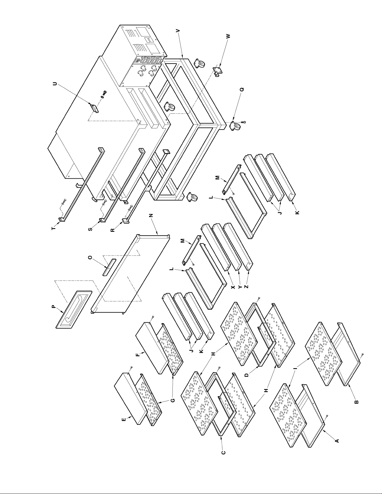
Page 28

IMPINGER X2 OVENS
GENERAL VIEW
LETTER PART NUMBER DESCRIPTION
A 9004415 Finger housing, bottom (3240), #5 left (3262, 3270)
B 9004415 Finger housing, bottom (3240), #6 right (3262, 3270)
C 9004422 Finger housing, middle (3240), #3 left (3262, 3270)
D 9004422 Finger housing, middle (3240), #4 right (3262, 3270)
E 9004416 Finger housing, top, (3240), #1 left (3262, 3270)
F 9004416 Finger housing, top, (3240), #2 right (3262, 3270)
G 7007757 Finger cover, top
H 7007168 Finger cover, middle
I 7007168 Finger cover bottom
J 1111302010 Air return, middle, upper model 3262, 3270
K 1001303010 Air return, lower model 3262
2001303020 Air return, lower model 3270
L 7007378 Finger guide assy. model 3240, 3262, 3270
M 7007378 Finger guide, rear
N 300801140-1 Door, solid - 3240
100801140-1 Door, solid – 3262
200801140-1 Door, solid – 3270
300801140 Door, w/window – 3240
100801140 Door, w/window – 3262
200801140 Door, w/window – 3270
O 2805112 Nameplate, Impinger X2
P 100804622 Sandwich door assy.
Q 100302900 Caster, 5”
100303900 Caster, 5” w/brake
R 300202036 Bottom finger support, 3240
100202036 Bottom finger support, 3262
200202036 Bottom finger support, 3270
S 9004447 Center finger support, 3240
9004443 Center finger support, 3262
9004417 Center finger support, 3270
T 9004448 Top finger support, 3240
9004434 Top finger support, 3262
9004418 Top finger support, 3270
U 100537902 Door latch assy.
V 9409 Oven base, high – 3240
9414 Oven base, low –3240
9402 Oven base, high – 3262
9411 Oven base, low – 3262
9404 Oven base, high – 3270
9412 Oven base, low – 3270
W 108003-1EP Hinge plate, left
108003-2EP Hinge plate, right
X 9004439 Center air return, upper – 3262
9004436 Center air return, upper – 3270
Y 9004440 Center air return, middle – 3263
9004437 Center air return, middle – 3270
Z 9004441 Center air return, lower – 3262
9004438 Center air return, lower - 3270
Impinger X2 – Analog Service Manual – Dom & Int’l28
Page 29
Impinger X2 – Analog Service Manual – Dom & Int’l 29
Page 30

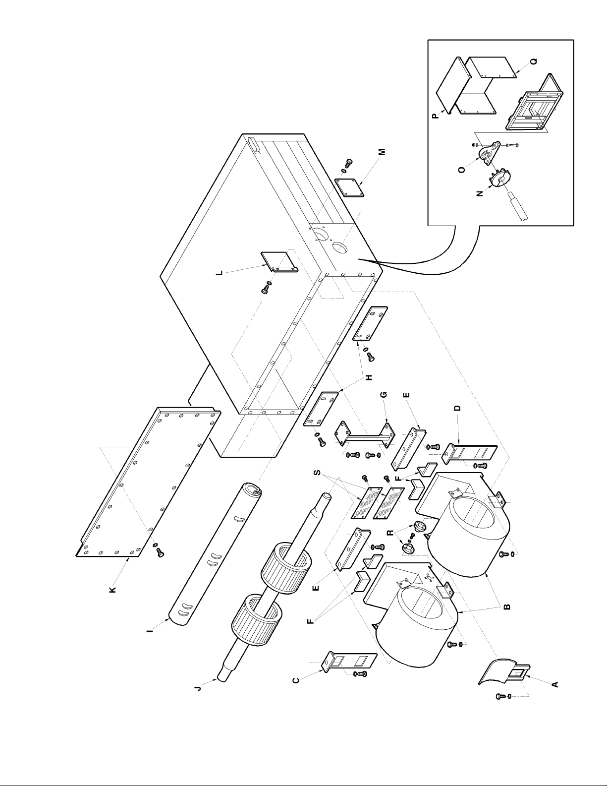
IMPINGER X2 OVENS
OVEN CAVITY
LETTER PART NUMBER DESCRIPTION
A 9004435 Guard, shaft – 3262
9004419 Guard, shaft – 3270
B 4071215 Housing, blower
C 100601417 Air return plate, right – 3240, 3262
200601417 Air return plate, right – 3270
D 100601417 Air return plate, left – 3240, 3262
200601417 Air return plate, left – 3270
E 100601394 Air dam, upper
F 100110224 Close-off, upper plenum
G 100102601 Support, oven cavity
H 100106000 Plate, connector
I 300601280 Extension tube, burner – 3240
100601280 Extension tube, burner – 3262
200601280 Extension tube, burner – 3270
J 300601328 Shaft, blower wheel assy. – 3240
100601328 Shaft, blower wheel assy. – 3262
200601328 Shaft, blower wheel assy. – 3270
K 3001401011 Oven back – 3240
1001401011 Oven back – 3262
2001401011 Oven back – 3270
L 100601334/100601336 Burner heat shield, outer, inner
M 100601324 Burner opening cover
N 390048 Heat slinger – 3240
390047 Heat slinger – 3262, 3270
O 390063 Bearing, idler
P 9004431 Top cover, idler end
Q 100120224 Cover, idler end
R 100110204 Flange, thermocouple mount
S 7007374 Guard, center air return – 3262
7007375 Guard, center air return - 3270
Impinger X2 – Analog Service Manual – Dom & Int’l30
Page 31
Impinger X2 – Analog Service Manual – Dom & Int’l 31
Page 32

IMPINGER X2 OVENS
CONTROL BOX
LETTER PART NUMBER DESCRIPTION
A 508120EP Coupling w/sleeve
B 100501329 Front cover –2 oven
100501327 Front cover – 2TS oven (split belt top)
100501326 Front cover – 2SB oven (split belt bottom)
100501325 Front cover –2SS oven (split belt top and bottom)
C 501176MEP Conveyor drive motor
D 501110EP Hall effect sensor
E 100507900/100507705 Pulley, shaft/ Sheave, driver
F 508202EP V-belt, 3240, 3262, 3270 – 60Hz. (BK 52 x 7/8”)
390069 V-belt, 3240, 3262, 3270 – 50Hz. (BK 45 x 7/8”)
G 390070 Pulley, motor, 3240, 3262, 3270 – 60 Hz.
390059 Pulley, motor, 3240, 3262, 3270 – 50 Hz.
H 4060276 Motor, main fan – 60 Hz. 1 phase
4060274 Motor, main fan – 60 Hz. 3 phase
4060275 Motor, main fan – 50 Hz. 1 phase
I 501070EP Air pressure switch
369575 Air pressure switch (CE ovens)
J 390075 Switch, conveyor reversing
K 501250-2EP Ignition control, 60 Hz. ovens
370396 Ignition control, 50 Hz. ovens
L/M 390067 Relay/overload, 3240
390068 Relay/overload, 3262, 3270
N 601492EP Cool-down timer, 120VAC
370466 Cool-down timer, 230VAC
O 4000214 Terminal block, 5-pole
P 100501232 Cover, rear
Q 9004432 Cover, control box top
R 369368 Thermostat, oven cavity hi-limit
S 4090413 Fuse holder, 6 position
T 501201EP Fuse, 2A
U 4070599 Fuse holder, 60 Hz. ovens
370342 Fuse holder, CE ovens (50 Hz.)
V Plug connector, diagnostic (part of wire harness)
W 501100EP Control, conveyor
X 390060 Switch, ON/OFF
Y 501085EP Control, temperature
Z 501090EP Thermocouple, type ”J”
AA 9004363 Control panel, -2 oven
9004364 Control panel, -2SB oven (split belt bottom)
9004365 Control panel, -2TS oven (split belt top)
9004347 Control panel, -2SS oven (split belt top and bottom)
BB 4071191 Strain relief
Not shown 370180 EMI Filter (Export only)
Not shown 370184 RFI Filter (Export only)
Impinger X2 – Analog Service Manual – Dom & Int’l32
Page 33

Impinger X2 – Analog Service Manual – Dom & Int’l 33
Page 34

IMPINGER X2 OVENS
BURNER/DRIVE END
LETTER PART NUMBER DESCRIPTION
A 7007124 Flange, burner
B 390048 Heat slinger, 3240
390047 Heat slinger, 3262, 3270
C 507500EP Bearing, drive end
D 501260EP Motor, burner blower
E 501250-8EP Relay, time delay
F 369531 Transformer, 120/24VAC
G 369142 Flame target
H 501250-1EP Igniter/sensor assy.
I 100501271 Shield, pilot
J Cable, spark
K 2605078 Orifice, pilot, Nat.
Orifice, pilot, L.P.
L 370059 Manifold, burner
M 369398 Valve, temperature regulation (120 VAC)
370186 Valve, temperature regulation (CE ovens, 220VAC)
N 50150-5EP Valve, main gas (24VAC)
370433 Valve, main gas (CE ovens, 220 VAC)
O 2605080 Orifice, main burner, Nat.
Orifice, Main burner, L.P.
P 369400 Moveable plate, air shutter
Q 369399 Air shutter
Impinger X2 – Analog Service Manual – Dom & Int’l34
Page 35

Impinger X2 – Analog Service Manual – Dom & Int’l 35
Page 36

IMPINGER X2 OVENS
CONVEYOR, SINGLE
LETTER PART NUMBER DESCRIPTION
A 100403103 Shelf, infeed side
100403101 Shelf, out take side
B 100403107 Pan stop, zero stop
C 10040710 Crumb pan (bottom conveyor only)
D 369005 Connecting link
E 100405831
100405810
100405830
405830-1EP Conveyor belt –1ft. section
F 390051 Bushing assembly, single belt
G 100404710 Shaft, idle end
H 406000EP Roller, smooth
I 405900EP Roller, notched
J 300403331
100403361
200403390
300403330
100403360
200403380
K 508103EP Coupling half
L 100404810 Shaft, drive end
Conveyor belt - complete, 3240
Conveyor belt - complete, 3262
Conveyor belt - complete, 3270
Frame assembly, upper conveyor, 3240
Frame assembly, upper conveyor, 3262
Frame assembly, upper conveyor, 3270
Frame assembly, lower conveyor, 3240
Frame assembly, lower conveyor, 3262
Frame assembly, lower conveyor, 3270
Impinger X2 – Analog Service Manual – Dom & Int’l36
Page 37

Impinger X2 – Analog Service Manual – Dom & Int’l 37
Page 38

IMPINGER X2 OVENS
CONVEYOR, DUAL BELT
LETTER PART NUMBER DESCRIPTION
A 100403103 Take off shelf, infeed side
100403101 Take off shelf, out take side
B 100403107 Pan stop, zero stop
C 100403710 Crumb pan (bottom conveyor only)
D 405849-2EP Connecting link
E 100405847
405849EP
100405844
405849-1EP Conveyor belt, 1ft. section
F 390050 Bushing assembly, dual belt
G 100404710 Shaft, idle end
H 406000EP Roller, smooth
I 405900EP Roller, notched
J 300403331
100403361
200403390
300403330
100403360
200403380
K 508103EP Coupling half
L 100404810 Shaft, drive
Conveyor belt, complete, 3240
Conveyor belt, complete, 3262
Conveyor belt, complete, 3270
Frame assembly, upper conveyor, 3240
Frame assembly, upper conveyor, 3262
Frame assembly, upper conveyor, 3270
Frame assembly, lower conveyor, 3240
Frame assembly, lower conveyor, 3262
Frame assembly, lower conveyor, 3270
Impinger X2 – Analog Service Manual – Dom & Int’l38
Page 39

Impinger X2 – Analog Service Manual – Dom & Int’l 39
Page 40

Impinger X2 – Analog Service Manual – Dom & Int’l40
 Loading...