

Lincoln 3255 Installation Manual
Impinger® Conveyor Oven
Series 3200, Models 3240 –3255 –3270
Installation, Operation and Maintenance Manual
Original Instruction
Part Number 20000095 Rev J 5/15
Safety Notices
As you work on Lincoln equipment, be sure to pay close
attention to the safety notices in this manual. Disregarding
the notices may lead to serious injury and/or damage to the
equipment.
Throughout this manual, you will see the following types of
safety notices:
DANGER
Text in a Danger box alerts you to an eminent personal
injury situation. Be sure to read the Danger statement
before proceeding, and work carefully.
Warning
Text in a Warning box alerts you to a potential personal
injury situation. Be sure to read the Warning statement
before proceeding, and work carefully.
Caution
Text in a Caution box alerts you to a situation in which
you could damage the equipment. Be sure to read
the Caution statement before proceeding, and work
carefully.
Procedural Notices
Warning
Improper installation adjustment, alteration, service
or maintenance can cause property damage, injury or
death. Read the installation, operating and maintenance
instructions thoroughly before installing or servicing
this equipment..
Warning
Authorized Service Representatives are obligated to
follow industry standard safety procedures, including,
but not limited to, local/national regulations for
disconnection / lock out / tag out procedures for all
utilities including electric, gas, water and steam.
Warning
This appliance is not intended for use by persons
(including children) with reduced physical, sensory
or mental capabilities, or lack of experience and
knowledge, unless they have been given supervision
concerning use of the appliance by a person responsible
for their safety. Do not allow children to play with this
appliance.
Warning
This equipment is intended for indoor use only. Do not
install or operate this equipment in outdoor areas.
As you work on Lincoln equipment, be sure to read the
procedural notices in this manual. These notices supply
helpful information which may assist you as you work.
Throughout this manual, you will see the following types of
procedural notices:
Important
Text in an Important box provides you with information
that may help you perform a procedure more efficiently.
Disregarding this information will not cause damage or
injury, but it may slow you down as you work.
NOTE: Text set off as a Note provides you with simple, but
useful, extra information about the procedure you are
performing.
Read These Before Proceeding:
DANGER
Do not install or operate equipment that has been
misused, abused, neglected, damaged, or altered/
modified from that of original manufactured
specifications.
Warning
Do not use electrical appliances or accessories other
than those supplied by the manufacturer.
FOR YOUR SAFETY
Do Not Store Or Use Gasoline Or Other Flammable
Vapors Or Liquids In The Vicinity Of This Or Any Other
Appliance.
Warning
Never use a high-pressure water jet for cleaning or hose
down or flood interior or exterior of units with water. Do
not use power cleaning equipment, steel wool, scrapers
or wire brushes on stainless steel or painted surfaces.
Caution
Maintenance and servicing work other than cleaning as
described in this manual must be done by authorized
service personnel.
NOTE: Proper installation, care and maintenance are essential
for maximum performance and trouble-free operation of
your equipment. Visit our website www.mtwkitchencare.
com for manual updates, translations, or contact information
for service agents in your area.

Section 1
General Information
Section 2
Installation
Section 3
Operation
Table of Contents
Standard Features ..............................................................................................................5
Purchaser’s Responsibility .................................................................................................5
Additional Requirements ....................................................................................................................5
Model Number Key ............................................................................................................6
Exterior Dimensions – 3240...............................................................................................7
Exterior Dimensions – 3255...............................................................................................8
Exterior Dimensions – 3270...............................................................................................9
Specifications ...................................................................................................................10
Canopy Ventilation Recommendations ..........................................................................12
Installation Requirements ...............................................................................................13
Gas Code Requirements ...................................................................................................................13
Electrical Code Requirements ......................................................................................................... 13
Spacing Requirements ......................................................................................................................14
Ventilation Requirements.................................................................................................................14
Restraint Requirement – Gas Oven(s) on Casters, U.S. and Australia ................................ 15
Installation ........................................................................................................................15
Unloading ..............................................................................................................................................15
Uncrating ................................................................................................................................................15
Manual Gas Valve Installation .........................................................................................16
Stand and Finger Assembly .............................................................................................16
Installation Checklist .......................................................................................................18
Checklist ................................................................................................................................................. 19
Start-Up Procedures .........................................................................................................19
Smoke Candle Test – Ventilation System Verification ............................................................. 19
Finger Housing Baffle Plate Adjustments ................................................................................... 20
Information on Use of Oven ............................................................................................21
Oven Start-Up Instructions .............................................................................................22
To Turn a Conveyor Off or Back On .................................................................................22
Oven Shut-Down Instructions .........................................................................................22
Section 4
Maintenance
Preventive Maintenance ..................................................................................................23
Daily Cleaning ..................................................................................................................23
Weekly Cleaning ...............................................................................................................24
Section 5
Troubleshooting
Before Calling for Service Checklist ................................................................................27
Thermal Cut-Out Switch for Control Box Components .................................................27
Part Number 20000095 Rev J 5/15 3

Table of Contents (continued)
THIS PAGE INTENTIONALLY LEFT BLANK
4 Part Number 20000095 Rev J 5/15

Section 1
General Information
Standard Features
• Faster bake times improve time of service.
• Advanced Air Impingement Technology enhances bake
quality and uniformity.
• Improved product flow during cooking reduces
operation costs.
• Research and Applications support for continued
operational success.
• New FastBake™ Technology designed to bake up to 35%
faster than other conveyor ovens without increased
noise levels or loss of product quality!
Purchaser’s Responsibility
It is the responsibility of the purchaser:
1. To see that the gas and electric services for the oven are
installed on site in accordance with the manufacturer’s
specification.
2. To unload, uncrate, and install the oven in its proper
location; in accordance with this installation/operation
manual.
3. To see that the gas and electric services are connected
properly by a qualified installer of your choice. For
installation in the State of Massachusetts: Installation
of this oven must be performed by a licensed
plumber or gas fitter. All such connections must be
in accordance with applicable code requirements.
Refer to “Installation Requirements” section for specific
information.
4. To arrange for inspection and operation check-out by
an Authorized Service Technician as described below:
Do not attempt to operate the oven until connection of
utility service has been fully inspected by an Authorized
Service Technician or a Lincoln Foodservice Products, LLC
Service Representative. This service is required by Lincoln
Foodservice Products, LLC in order to assist the purchaser in
proper start-up of the oven on site. Please note the specific
details on the Warranty and make certain connections are
made to proper utility services.
The warranty shall not apply if the oven(s) are started up
and operated prior to the utilities and oven being inspected
and check-out made by an Authorized Service Technician or
a Lincoln Foodservice Products, LLC Service Representative.
ADDITIONAL REQUIREMENTS
• Obtain from your local gas provider and post in a
prominent location instructions to be followed in the
event gas odors are detected.
• It is required that the oven be placed under a ventilation
hood to provide for adequate air supply and ventilation.
• Minimum clearances must be maintained from all walls
and combustible materials. See “Spacing Requirements”
section for more information.
• Keep the oven free and clear of combustible material.
• Adequate clearance for air openings to the combustion
control chamber on the right side of the oven is
required.
• Do not obstruct the ventilation holes in the control
panels, as these provide the combustion air for the
burner and cooling air for the controls.
• The oven is to be operated only on the type of gas and/
or electricity as shown on the specification plate.
• The power burner will not operate and gas will not flow
through the burner without electrical power.
• This manual should be retained for future reference.
• The electrical wiring diagram is located under the
control box covers.
IN AUSTRALIA: Refer to Standard AS 5601. This standard
specifies the requirements for piping, flues, ventilation and
appliance installation associated with use of or intended
use of fuel gases. The requirements of AS 5601 are to be
used in conjunction with, but do not take precedence over,
any statutory regulations that may apply in any area.
All ovens require separate service and dedicated neutral.
Gas Pressure Conversion
Inches of Water
Column
3.5
4.5
7
10
10.5
11
14
14.5
kPa m-Bar
0.87
1.12
1.74
2.48
2.61
2.73
3.48
3.61
8.70
11.2
17.40
24.87
26.11
27.36
34.81
36.05
Millimeters of
Water Column
88.9
114.3
177.8
254.0
266.7
279.4
355.6
368.3
Part Number 20000095 Rev J 5/15 5
General Information Section 1
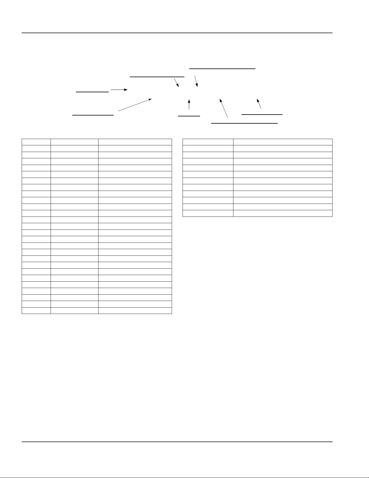
Model Number Key
Example: 3240-000-L-K2300
CUSTOM CONFIGURATION CODE
LANGUAGE/AGENCY CODE
TUNNEL DEPTH
(i.e. General Market or Customer Specific)
32 40 0 0–––0 L K2300
OVEN TUNNEL WIDTH
Code Language Country
0 English Dom. & Int. Default
B French CE – France/Luxembourg
C German CE – Germany
D Italian CE – Italy
E Spanish CE – Spain
F English CE – UK/India/Africa/Hungary
G Spanish Mexico/Latin America
H Portuguese CE – Portugal
I Not Used ---
J Danish CE – Denmark
K Dutch & French CE – Belgium
L Dutch CE – Netherlands
M Greek CE – Greece
N Finnish CE – Finland
O Restricted --P Norwegian CE – Norway
Q English Japan
R Swedish CE – Sweden
S English Australia
T Mandarin China
U Restricted --V English Pacific Rim/Korea
W English Middle East/Africa
X Not Used --Y Not Used --Z Not Used ---
BELT TYPE
0 = Solid Belt
5 = Split Belt
PANEL SETUP CODE
FUEL TYPE/ELECTRICAL SUPPLY
N = Natural
Code Fuel Type
B 400V/230V/3Ph/50Hz
D 380V/220V/3Ph/50Hz
G 415V/240V/3Ph/50Hz
J 208V/1Ph/60Hz
M 220V/1Ph/60Hz
P 240V/1Ph/60Hz
R 208V/3Ph/60Hz
S 480V/3Ph/60Hz
V 240V/3Ph/60Hz
N Natural
L Propane
6 Part Number 20000095 Rev J 5/15
Exterior Dimensions – 3240
77.61" (1971 mm)
26.02"
(661 mm)
17.44"
(443 mm)
11.66"
(296 mm)
40.41" (1026 mm)
Section 2
Installation
17.4"
(442 mm)
23.13"
(588 mm)
37.49"
(952 mm)
77.75"
(1975 mm)
60.34"
(1533 mm)
39.78"
(1010 mm)
19.22"
(488 mm)
61.86"
(1571 mm)
Part Number 20000095 Rev J 5/15 7
Installation Section 2
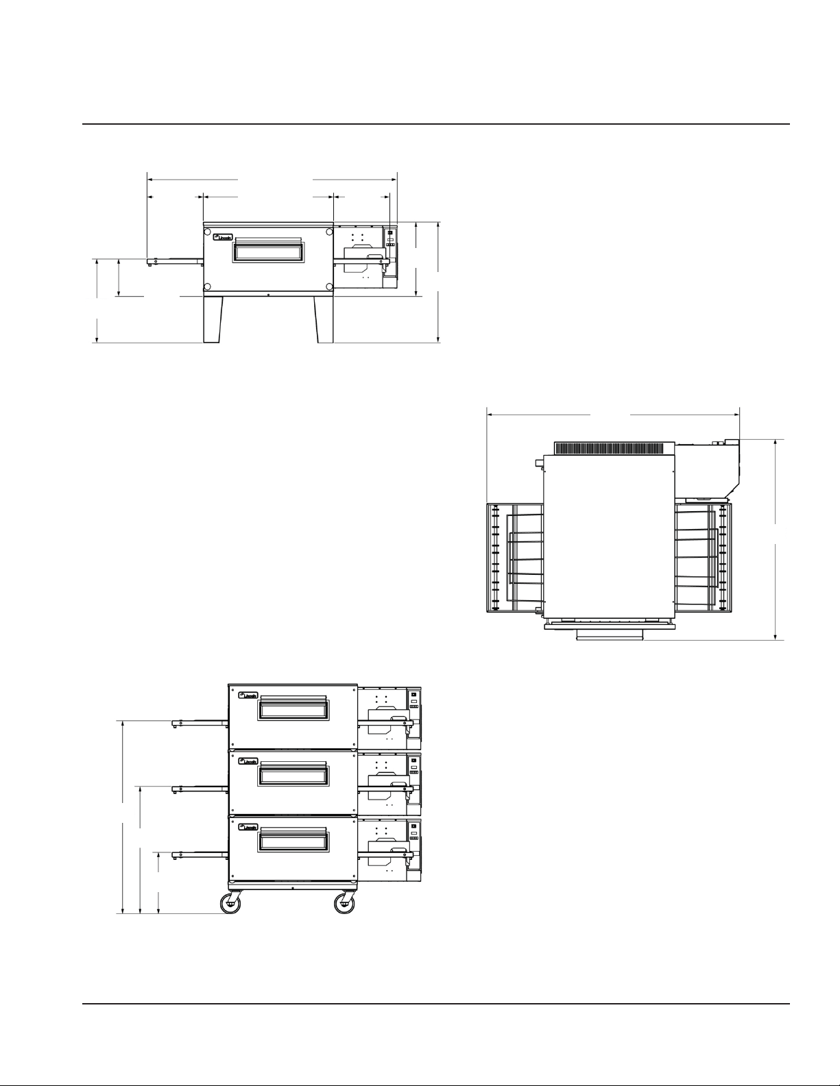
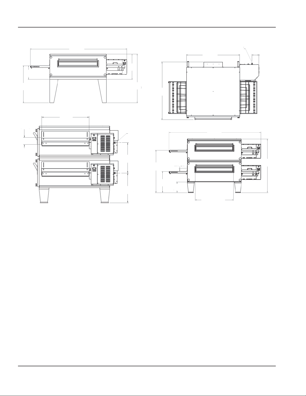
Exterior Dimensions – 3255
Gas Supply
1/2" NPT
7-1/16"
(179 mm)
13-1/8"
(333 mm)
94"
(2347 mm)
24-1/2"
(622 mm)
55"
(1400 mm)
36"
(914 mm)
5"
(127 mm)
33-3/4"
(857 mm)
47-3/8"
(1203 mm)
1/2" NPT
21-5/8"
(549 mm)
21-1/4"
(540 mm)
(Gas)
59-5/8"
(1515 mm)
43-1/4"
(1098 mm)
21-5/8"
(549 mm)
3-1/4"
(80 mm)
Door Open
10-7/8"
(276 mm)
93-3/4"
(2381 mm)
38-3/4"
(984 mm)
Shown with open
glass access door
54-3/4"
(1391 mm)
8 Part Number 20000095 Rev J 5/15
Section 2 Installation
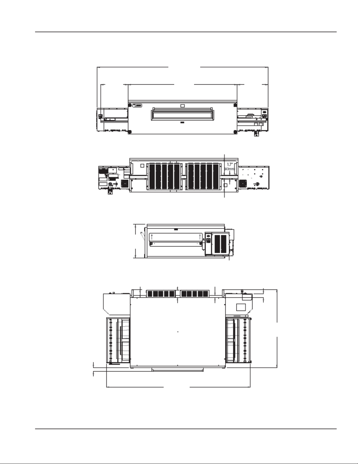
Exterior Dimensions – 3270
Control Box
109.7"
(2786 mm)
17.5"
(445 mm)
21.7"
(551 mm)
70"
(1778 mm)
11.2"
(284 mm)
8.8"
(223 mm)
19.9"
(505 mm)
1.5"
(38 mm)
2.8"
(71 mm)
57.4"
(1458 mm)
2.9"
(74 mm)
6"
(152 mm)
5.5"
(140 mm)
106.1"
(2695 mm)
Conveyor
Part Number 20000095 Rev J 5/15 9
Installation Section 2
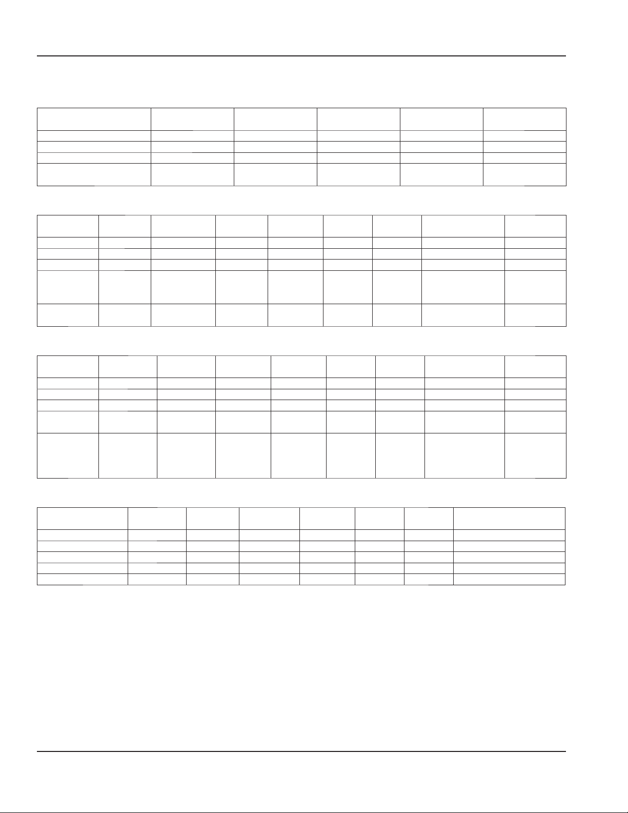
Specifications
Electrical Service — All Gas Models
Voltage (AC) Phase Hz
Single Oven 120 1 60 6.0 14.0
Double Stack 120 1 60 12.0 28.0
Triple Stack 120 1 60 18.0 42.0
International Ovens
(Single Stack)
230/240 1 50 3.15 7.3
Model 3240/3255
Amps
General Information – 3240 Natural Gas Ovens
Model Energy Power Voltage Current Phase Hz
Single Oven Nat. Gas 115,000 BTU 120 VAC 6 Amps 1 60 Hz 8 – 14" W.C. 1"
Double Stack Nat. Gas 230,000 BTU 120 VAC 12 Amps 1 60 Hz 8 – 14" W.C. 1-1/4"
Triple Stack Nat. Gas 345,000 BTU 120 VAC 18 Amps 1 60 Hz 8 – 14" W.C. 1-1/2"
Single Oven Nat. Gas
G20
Single Oven Nat. Gas
G25
31 kW (HI)
144 MS/hr
3
3.88 m
/hr
26 kW (HI) 230 VAC 3.15 Amps 1 50 Hz 2.00 - 3.48 kPa 1"
230 VAC 3.15 Amps 1 50 Hz 2.00 - 3.48 kPa 1"
Gas Supply
Pressure
Model 3270
Amps
Gas Pipe Size
(NPT)
General Information – 3240 Propane Gas Ovens
Model Energy Power Voltage Current Phase Hz
Single Oven L.P. Gas 115,000 BTU 120 VAC 6 Amps 1 60 Hz 11.5 – 14" W.C. 3/4"
Double Stack L.P. Gas 230,000 BTU 120 VAC 12 Amps 1 60 Hz 11.5 – 14" W.C. 1"
Triple Stack L.P. Gas 345,000 BTU 120 VAC 18 Amps 1 60 Hz 11.5 – 14" W.C. 1-1/4"
Single Oven L.P. Gas
G30
Single Oven L.P. Gas
G31
37 kW (HI)
2.315 kg/hr
31 kW (HI)
144 MS/hr
3
1.14 m
/hr
2.545 kg/hr
230 VAC 3.15 Amps 1 50 Hz 2.85 – 3.48 kPa 3/4"
230 VAC 3.15 Amps 1 50 Hz 2.85 – 3.48 kPa 3/4"
Gas Supply
Pressure
Gas Pipe Size
(NPT)
General Information – 3240 Electric Ovens
Model Energy Power Voltage Current Phase Hz
3240-XXX-B-KXXXX Electric 24kW 400/230 Vac 35 Amps 3 50 Hz 5 Wires, 3 Poles 1N-1G
3240-OXX-R-KXXXX Electric 24kW 120/208 Vac 67 Amps 3 60 Hz 4 Wires, 3 Poles -1G
3240-OXX-V-KXXXX Electric 24kW 120/240 Vac 58 Amps 3 60 Hz 4 Wires, 3 Poles -1G
3240-XXX-D-KXXXX Electric 24kW 380Y/220 Vac 37 Amps 3 50 Hz 5 Wires, 3 Poles 1N-1G
3240-XXX-G-KXXXX Electric 24kW 415Y/240 Vac 34 Amps 3 50 Hz 5 Wires, 3 Poles 1N-1G
Recommended Electrical
Specifications
10 Part Number 20000095 Rev J 5/15

Section 2 Installation
General Information – 3255 Natural Gas Ovens
Model Energy Power Voltage Current Phase Hz
Gas Supply
Pressure
Single Oven Nat. Gas 145,000 BTU 120 VAC 6 Amps 1 60 Hz 8 – 14" W.C. 1"
Double Stack Nat. Gas 290,000 BTU 120 VAC 12 Amps 1 60 Hz 8 – 14" W.C. 1-1/4"
Triple Stack Nat. Gas 435,000 BTU 120 VAC 18 Amps 1 60 Hz 8 – 14" W.C. 1-1/2"
Single Oven Nat. Gas 42.5 kW (HI)
230 VAC 1 50 Hz 2.00 - 3.48 kPa 1"
153 MS/h
3
4.44 m
/hr
Gas Pipe Size
(NPT)
General Information – 3255 Propane Gas Ovens
Model Energy Power Voltage Current Phase Hz
Gas Supply
Pressure
Single Oven L.P. Gas 145,000 BTU 120 VAC 6 Amps 1 60 Hz 11.5 – 14" W.C. 3/4"
Double Stack L.P. Gas 290,000 BTU 120 VAC 12 Amps 1 60 Hz 11.5 – 14" W.C. 1"
Triple Stack L.P. Gas 435,000 BTU 120 VAC 18 Amps 1 60 Hz 11.5 – 14" W.C. 1-1/4"
Single Oven L.P. Gas
G30
42.5 kW (HI)
153 MS/h
3
1.30 m
/hr
230 VAC 3.15 Amps 1 50 Hz 2.85 – 3.48 kPa 3/4"
3.208 Ks/hr
Single Oven L.P. Gas
G31
42.5 kW (HI)
153 MS/h
230 VAC 3.15 Amps 1 50 Hz 2.85 – 3.48 kPa 3/4"
2.918 Ks/hr
Gas Pipe Size
(NPT)
General Information – 3270 Natural Gas Ovens
Model Energy Power Voltage Current Phase Hz
Gas Supply
Pressure
Single Oven Nat. Gas 150,000 BTU 120 VAC 14 Amps 1 60 Hz 8 – 14" W.C. 1"
Double Stack Nat. Gas 300,000 BTU 120 VAC 28 Amps 1 60 Hz 8 – 14" W.C. 1-1/4"
Triple Stack Nat. Gas 450,000 BTU 120 VAC 42 Amps 1 60 Hz 8 – 14" W.C. 1-1/2"
International
(Single Stack)
Nat. Gas 43.9 kW Hi
158.26 MJ
3
4.59 m
/hr
230/240 VAC 7.3 Amps 1 50 Hz 17.4 mbar
2.00 – 3.48 kPa
Gas Pipe Size
(NPT)
1"
General Information – 3270 Propane Gas Ovens
Model Energy Power Voltage Current Phase Hz
Gas Supply
Pressure
Single Oven L.P. Gas 150,000 BTU 120 VAC 14 Amps 1 60 Hz 11.5 – 14" W.C. 3/4"
Double Stack L.P. Gas 300,000 BTU 120 VAC 28 Amps 1 60 Hz 11.5 – 14" W.C. 1"
Triple Stack L.P. Gas 450,000 BTU 120 VAC 42 Amps 1 60 Hz 11.5 – 14" W.C. 1-1/4"
International
(Single Stack)
L.P. Gas
G30
43.9 kW Hi
158.26 MJ
3
1.3 m
/hr
230/240 VAC 7.3 Amps 1 50 Hz 27.4 mbar
2.85 – 3.48 kPa
3.32 kg/hr
Single Stack LP Gas
G31
43.9 kW Hi
158.26 MJ
3
1.3 m
/hr
230/240 VAC 7.3 Amps 1 50 Hz 27.4 mbar
2.85 – 3.48 kPa
3.01 kg/hr
Gas Pipe Size
(NPT)
3/4"
3/4"
NOTE: For proper operation, the gas valve requires a nominal inlet pressure of 7 inches H2O column for natural gas and
11 inches of H2O column for L.P. gas, unless otherwise specified. A minimum inlet pressure of 1.0 inch of H2O above the
manifold setting (NAT. manifold 3.5" H2O, L.P. manifold 10" H2O) must be maintained with no pressure drop from the no load
to full load condition. The maximum inlet pressure must be maintained at or below 1/2 PSIG (14.5 inches H2O column). Refer
to the Gas Pressure Conversion chart in Section 1 for pressure conversions.
Part Number 20000095 Rev J 5/15 11
Installation Section 2
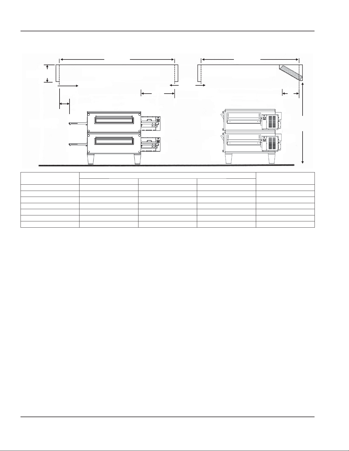
Canopy Ventilation Recommendations
18"-24"
457 mm - 610 mm
Capture Velocity
A
Capture Area Capture Area
Capture
Velocity
D
C
B
Dimension
3240 3255 3270
A 96 in (2438 mm) 108 in (2743 mm) 120 in (3048 mm) 10 ft (3039 mm)
B 8 in (203 mm) 8 in (203 mm) 8 in (203 mm) 22 in (559 mm)
C 22 in (559 mm) 22 in (559 mm) 22 in (559 mm) 22 in (559 mm)
D 80 in (2032 mm) 80 in (2032 mm) 80 in (2032 mm) 6 ft 8 in (2020 mm)
E 12 in (305 mm) 12 in (305 mm) 12 in (305 mm) 12 in (304 mm)
F 80 in (2032 mm) 80 in (2032 mm) 80 in (2032 mm) 6 ft 6 in AFF (1981 mm)
Exhaust Flow 1400 – 1600 CFM 1600 – 2000 CFM 1800 – 2400 CFM —
Single or Double Stack
E
F
Triple Stack *
AFF = Above Finished Floor
* Hood dimensions shown are for island mount - Size reductions may be possible for wall mount units.
NOTE: Hood dimensions and the positioning of the hood
over the oven will vary with hood manufacturers.
NOTE: Lincoln can provide oven spec sheets that show
the dimensions of the oven, kW or BTU ratings and other
information that will be useful to both the ventilation hood
supplier and the HVAC contractor.
12 Part Number 20000095 Rev J 5/15
Section 2 Installation
Installation Requirements
DANGER
All utility connections and fixtures must be maintained
in accordance with local and national codes.
GAS CODE REQUIREMENTS
DANGER
Conversion of this appliance from one type of gas to
another must only be performed by qualified, licensed,
and authorized installation or service personnel.
Conversion without the proper components may result
in fire or explosion.
Warning
A manual shut-off valve must be installed in the gas
supply (service) line upstream of this appliance and in a
position where it can be reached quickly in the event of
an emergency.
Safe and satisfactory operation of this oven depends to a
great extent upon its proper installation, and it should be
installed, as applicable in accordance with the National
Fuel Gas Codes, ANSI Z223.1/NFPA 54, latest version,
manufacturers’ installation instructions and local municipal
building codes.
1. The oven and its individual shut off valve must be
disconnected from the gas supply piping system
during any pressure testing of that system at test
pressures in excess of 1/2 psig (3.45 kPa).
2. The oven must be isolated from the gas supply piping
system by closing its individual manual shutoff valve
during any pressure testing of the gas supply system at
test pressures equal to or less than 1/2 psig (3.45 kPa).
IN MASSACHUSETTS: The minimum length of a flexible gas
supply hose is thirty-six (36") inches.
IN CANADA: The installation of these appliances is to be in
accordance with CSA B.149.1 latest version – Natural Gas
and Propane Installation Code – and/or local codes.
IN AUSTRALIA: To be installed in accordance with AS 56012004 and 4563-2004 Gas Installation Code.
NOTE: In the event that verification of pilot flame is needed,
a small mirror may be utilized for verification.
ELECTRICAL CODE REQUIREMENTS
Warning
This appliance must be grounded and all field wiring
must conform to all applicable local and national
codes. Refer to rating plate for proper voltage. It is the
responsibility of the end user to provide the disconnect
means to satisfy the authority having jurisdiction.
Warning
This equipment must be positioned so that the plug is
accessible unless other means for disconnection from
the power supply (e.g., circuit breaker or disconnect
switch) is provided.
When installed, this appliance must be electrically
grounded and its installation must comply with the
National Electric Code, ANSI-NFPA 70, latest edition, the
manufacturers’ installation instructions, and applicable local
municipal building codes.
IN CANADA: All electrical connections are to be made
in accordance with CSA C22.2 latest version – Canadian
Electrical Code and/or local codes.
ALL OTHER COUNTRIES: Local gas and/or electrical codes
will prevail.
1. Strain Relief is provided with each oven. International
Dealer/Distributors provide applicable power cord/
plug for each customer.
2. All pole disconnection switch must have 3 mm open
contact distance.
3. To prevent electrical shock, an equal potential bonding
ground lug is provided in the back. This allows the oven
to be connected to an external bonding system.
4. If used as double or triple stack and each oven has its
own disconnection switch, all switches should be close
together.
If flexible services are provided, they must meet code
requirements for such installation.
Part Number 20000095 Rev J 5/15 13

Installation Section 2
SPACING REQUIREMENTS
Warning
To avoid instability the installation area must be capable
of supporting the combined weight of the equipment
and product. Additionally the equipment must be level
side to side and front to back.
The oven must have 6 inches (152 mm) of clearance from
combustible surfaces. In case other equipment is located
on the right side of oven, a minimum clearance of 24 inches
(609 mm) is required from that equipment.
FOR ALL OVENS: A 24-inch (609 mm) clearance at the rear of
the oven must be obtainable for service access.
FOR PERMANENTLY INSTALLED OVENS: A permanently
installed (unmovable) oven requires a minimum of 13 feet
clearance on the right hand side to allow for conveyor
removal, cleaning, and servicing.
NOTE: Do not install this (these) oven(s) in any area with an
ambient temperature in excess of 95°F/35°C. Doing so will
cause damage to the unit.
VENTILATION REQUIREMENTS
A VENT IS REQUIRED: Local codes prevail. These are the
“authority having jurisdiction” as stated by the NATIONAL
FIRE PROTECTION ASSOCIATION, INC. in NFPA 96 latest
edition. In addition, to be in compliance with the NFPA 54
Section 10.3.5.2, this unit must be installed with a
ventilation hood interlock that prevents the unit from
operating when the ventilation hood is off. For further
ventilation information, see below.
Ventilation Guidelines
A ventilation hood is required to remove heat and cooking
odors. For gas ovens, a ventilation hood is also required to
remove the products of combustion. The hood and HVAC
installation must meet local codes to gain approval by
the authority having jurisdiction. Requirements may vary
throughout the country depending on the location by city,
county, and state. Obtain information from the authority
having jurisdiction to determine the requirements for your
installation. (NOTE: This oven is considered as “Light Duty
for Baking” when evaluated for code vent requirements.)
Obtain information and review copies of codes or
documents that will be used to inspect and approve your
installation. Your ventilation hood supplier and HVAC
contractor should be contacted to provide guidance. A
properly engineered and installed ventilation hood and
HVAC system will expedite approval and reduce oven
maintenance costs. Proper ventilation is the oven owner’s
responsibility.
The ventilation hood must operate in harmony with
the building HVAC system. It typically requires between
1600 and 2800 CFM exhaust or more with 70% makeup air. (The “Efficiency” of various hood designs makes it
necessary to specify such a wide range of ventilator CFM.)
Make up air must be supplied by either a hood design or
the HVAC system. This will vary with hoods from various
manufacturers.
Caution
Prevent airflow through the cooking tunnel. Air must
NOT be directed onto the oven front or at side of cooking
area or rear of oven.
Ventilation System
NOTE: These ovens are considered “Light Duty for Baking”
when evaluated for code vent requirements.
This information is shown as a guideline for ventilation.
1. Dimensions shown are for ovens without extension
shelves. The outside end of the conveyor frame must be
a minimum of 8 inches inside the canopy as shown.
2. The capture velocity across the lower edge of the
canopy is to be 50 FPM at sides and front.
3. Use filters at rear exhaust area of hood, as shown.
4. At start-up, the CO level must be checked around the
oven space under the canopy.
5. This level must be < 10ppm.
6. The ovens are to be centered in the canopy space leftto-right and front-to-back if possible.
7. A 6-inch space at rear of oven is recommended for
utilities.
8. Recommend 70% make-up air provided outside of the
canopy through perf metal diffusers directed straight
down — not at the oven; located at front, sides or both.
9. Room air diffusers must not be directed onto the oven
and should be positioned a minimum of 3 feet from the
perimeter of the hood to keep them from affecting the
oven.
14 Part Number 20000095 Rev J 5/15
Section 2 Installation
RESTRAINT REQUIREMENT GAS OVENS ON
CASTERS, U.S. AND AUSTRALIA
DANGER
Legs or casters must be installed and the legs or casters
must be screwed in completely to prevent bending.
When casters are installed the mass of this unit will
allow it to move uncontrolled on an inclined surface.
These units must be tethered/secured to comply with
all applicable codes.
• The installation shall be made with a gas connector that
complies with the Standard for Connectors for Movable
Gas Appliances, ANSI Z21.69 latest version, and a quick
disconnect device that complies with the Standard for
Quick Disconnect Devices for Use With Gas Fuel, ANSI
Z21.41 latest version.
IN CANADA: The installation shall be made with gas
connectors that comply with Canadian Code CSA 6.16
latest version and quick disconnects complying to
Canadian Code CSA 6.9 latest version.
IN AUSTRALIA: To be installed in accordance with AS
5601-2004 and 4563-2004 Gas Installation Code.
• The installation of the restraint must limit the
movement of the oven(s) without depending on the
connector, the quick disconnect device or its associated
piping to limit the oven movement.
• If the restraint must be disconnected during
maintenance or cleaning, it must be reconnected after
the oven has been returned to its originally installed
position.
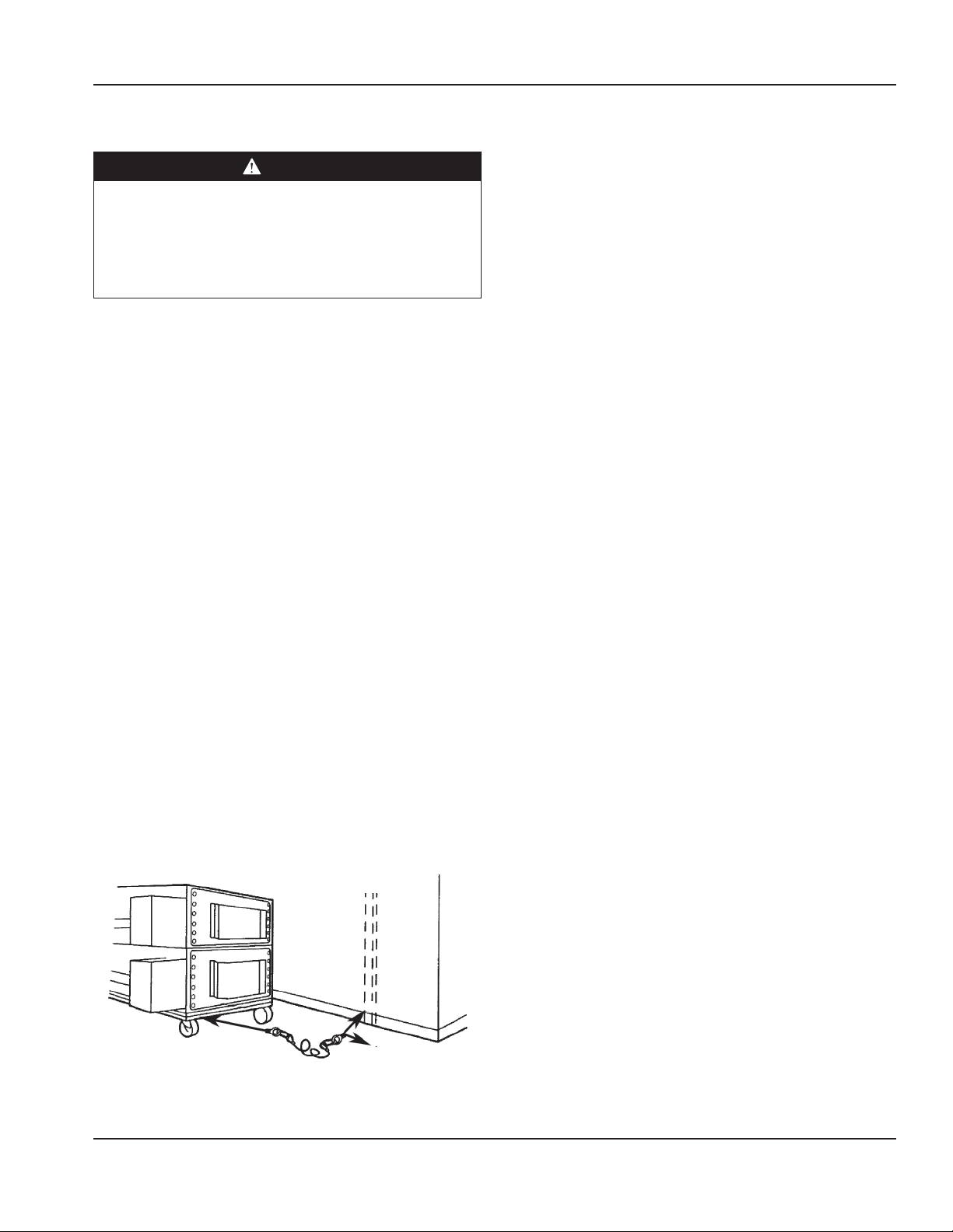
Procedure
1. Screw lifting eye “B” of cable assembly to hole “A”.
2. Screw eye bolt “C” of cable assembly to stud in wall “D”
or floor anchor “E”.
NOTE: Installation point is the same for single or stacked
ovens.
Back of Oven
Wall
Wall
A
B
Stud
D
C
E
Floor
Installation
The instructions that follow are intended as a guide for
preparing for the installation of the Impinger® Conveyor
Ovens, Series 3240C, 3255 and 3270. First and foremost,
each crate should be examined before signing the Bill of
Lading to report any visible damage caused by the trucker
in transit, and to account for the proper number of crates.
UNLOADING
When the oven arrives it should consist of:
1. A crate containing oven body, conveyor, fingers, crumb
pans, and pan stops. (Some models may have the
conveyor packed separately.)
2. A package containing the stand and top.
It is recommended that you have a material-handling
device available to unload.
DO NOT LIFT EXCESSIVE WEIGHT!
IF THERE IS APPARENT DAMAGE:
UNITED STATES AND CANADA: Arrangements should
be made to file a claim against the carrier, as Interstate
Commerce Regulations require that the consignee initiate
a claim.
ALL SHIPMENTS TO OTHER COUTRIES: Freight terms will be
developed and extended on an individual basis.
Proper and secure storage facilities should be arranged for
the oven(s). If necessary, protect it from outdoor or damp
conditions at all times before installation.
UNCRATING
When you have all the crates unloaded, open the crates and
remove the plastic covers. Inspect at once for concealed
damage. If anything appears to be damaged, contact the
appropriate persons immediately to file a damage claim.
After completing this inspection, finish unpacking the oven
and all other components. Be sure to remove the cardboard
from the plenum shroud. Move all components inside near
the area where they will be assembled in the order in which
they will be assembled.
THE OVEN WILL CLEAR THROUGH A 30" (762 mm)
DOORWAY BY USING THE FOLLOWING PROCEDURE:
1. Remove conveyor; see “Weekly Cleaning” section for
instructions. (Some units may have conveyor packed
separately.)
2. Remove thumb screws and baffle from the left side of
the oven.
Part Number 20000095 Rev J 5/15 15
Installation Section 2
3. Place the left side on a four wheel moving dolly and it
will clear a 30" (762 mm) doorway. Or oven can remain
on skid and be tilted on its back. Then placed on two
four-wheel dollies.
Caution
Do not lift the ovens using the control enclosure. Lift
from the main oven cavity only. Damage may occur to
the controls of the oven if lifted by the control enclosure.
Manual Gas Valve Installation
When installing the gas valve that is supplied with the oven
it is our suggestion that an elbow be placed on the oven
pipe first. This will allow the flexible hose to be attached in a
downward direction, eliminating possible stress to the hose.
Specifications
Body: Stainless Steel Power: Gas and/or Electric
DB Level: ≤ 71dba Operating Temperature Range:
300°F - 600°F (149°C - 316°C)
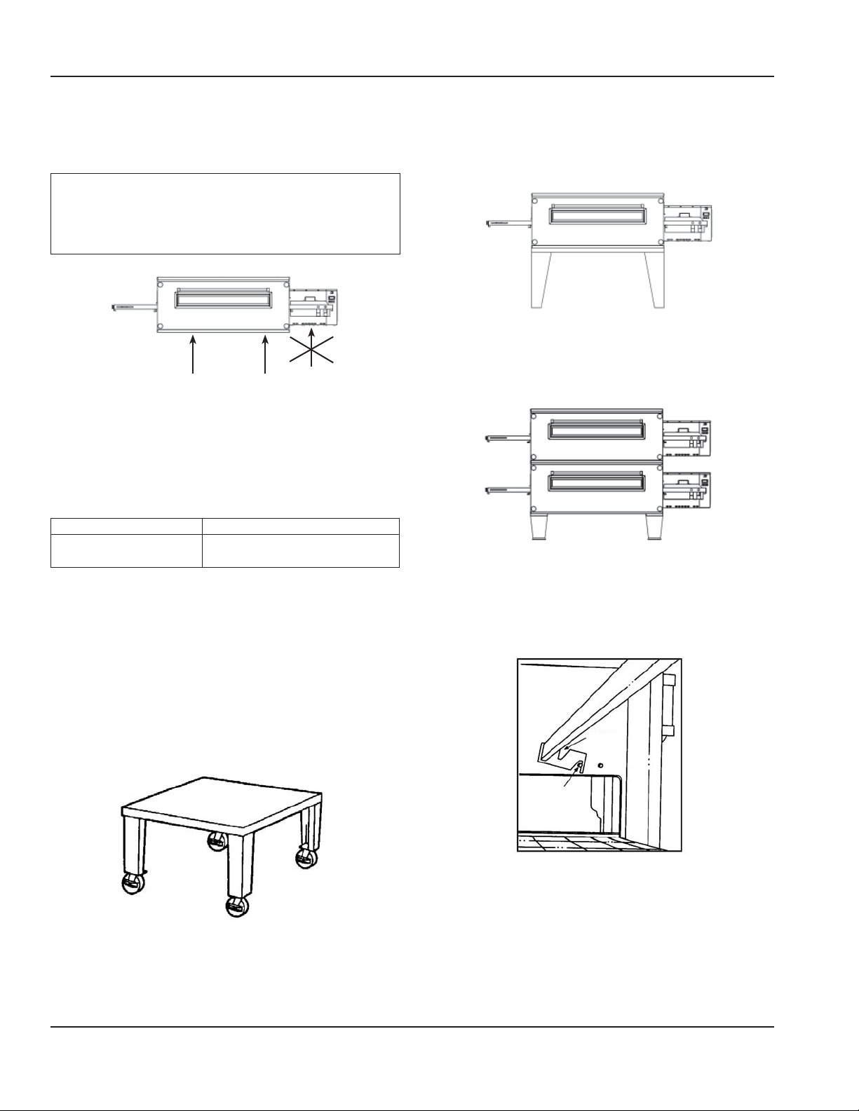
Stand and Finger Assembly
NOTE: 3255 is used for illustration.
1. The stand is a 55" (1397 mm) x 49" (1245 mm)
rectangle. Set it in place with a 55" side facing out. This
will be the front of the oven. Using a carpenter’s level,
level all four (4) sides of the stand. To raise or lower the
stand, use the leg adjusters. Ovens on casters require
a level floor. NOTE: The oven top is packed with oven
stand. Remove top from stand before assembly.
2. Remove the oven from the dolly and set it on the stand.
The control panel should be on the right rear as you
face the oven. Be sure that the oven sets squarely on
the stand and is fully seated. For a single oven, install
top. For double, see step 3.
3. If you purchased a double stack oven, place the second
oven on top of the first one. Be sure that it sets on
squarely and is fully seated. The control panel goes on
the right rear. Now install oven top.
4. Before installing the retaining brackets in the oven(s),
be sure all of the packing material is removed from the
plenum shroud. Install the finger retaining brackets by
placing them upside down and hooking the retaining
pin as shown.
Notch
Pin
16 Part Number 20000095 Rev J 5/15
Section 2 Installation
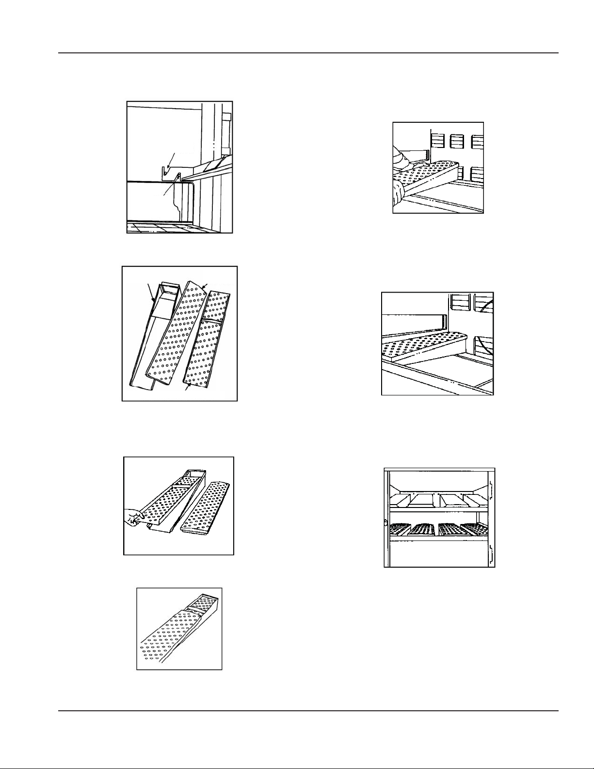
5. Rotate the finger brackets until the notches in the
brackets sit on the retaining pins.
Notch
Pin
6. Assemble fingers as shown in steps 7 and 8.
Finger
Housing
Finger
Cover
9. Insert assembled finger through door opening starting
with lower left. NOTE: The customer MUST tell you
what position to place the assembled finger in, for their
application.
10. Install finger in the oven by sliding it over the plenum
flange and setting the front bracket. BE SURE THAT THE
FINGER SITS SQUARELY OVER THE PLENUM FLANGES
AND THE HOLES POINT IN THE PROPER DIRECTION. Top
fingers point down, bottom fingers point up.
Number Stamped in Panel
7. Insert columnating plate so the step goes under the lip
of the finger housing and the plate lies flush with the
housing side edge.
8. Install cover by sliding it on the small end.
11. Repeat step 10 until all ten (10) fingers are installed.
Install conveyor and crumb pans before operation. See
“Weekling Cleaning” in Section 4 for instructions.
Part Number 20000095 Rev J 5/15 17
Installation Section 2
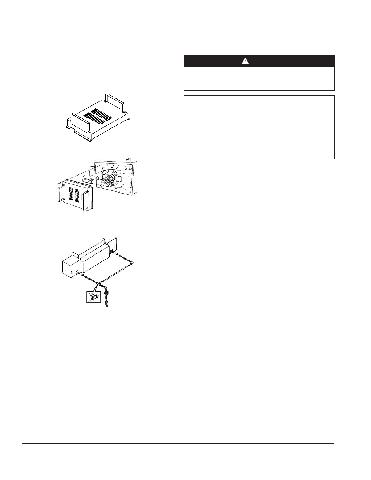
12. Attach Motor Cover as shown with bolts provided.
You are now ready for services to be connected.
This should be done by licensed electricians and
plumbers. See “Specifications” section and “Installation
Requirements” section for more information.
Motor Cover
13. The gas piping manifold kit should be installed as
shown.
Installation Checklist
DANGER
Check all wiring connections, including factory
terminals, before operation. Connections can become
loose during shipment and installation.
Warning
On completion of any installation or service work, test for
gas leaks before returning the equipment into service.
Never use matches, candles, or any other ignition source
to check for leaks. If gas odors are detected, shut off the
gas supply to the appliance at the main shut-off valve
and immediately contact the local gas company or an
authorized service agency for service.
DO NOT ATTEMPT TO OPERATE THE OVEN until
connection of utility service and installation has been
fully inspected (START-UP CHECKOUT) by an Authorized
Service Technician or a Lincoln Foodservice Products, LLC
Service Representative. This service is required by Lincoln
Foodservice Products, LLC in order to insure the oven(s)
is properly installed and in working order. The warranty
becomes effective upon verification of proper installation.
The warranty shall not apply if the oven is started up
and operated prior to the “START-UP CHECKOUT” being
performed by an Authorized Service Technician or a Lincoln
Foodservice Products, LLC Service Representative.
18 Part Number 20000095 Rev J 5/15
 Loading...