

Page 1

SERVICE MANUAL
FUSION TOASTER
MODEL SERIES 2030 & 2040
Lincoln Foodservice Products, LLC
1111 North Hadley Road
Fort Wayne, Indiana 46804
United States of America
Phone : (260) 459-8200
U.S. Fax: (888) 790-8193 • Int’l Fax: (260) 436-0735
Technical Service Hot Line
(800) 678-9511
www.lincolnfp.com
FusionServiceMan REV: B
Page 2

TABLE OF CONTENTS
SEQUENCE OF OPERATION (DOMESTIC UNITS)…................................................... .............................. 3
SEQUENCE OF OPERATION (EXPORT UNITS)………………………………………………………………… 4
SCHEMATICS………………………………………………………………………………………..………………. 5
TROUBLESHOOTING……………………………………………………………………………………………….. 10
OPERATING INSTRUCTIONS…………………………………………………………………………………..…. 14
SPARE PARTS LISTS & DRAWINGS………………………………………………………………..……………. 24
Fusion Toaster Series Service Manual
2
Page 3

SEQUENCE OF OPERATION
FUSION DOMESTIC MODELS
MODEL VOLTAGE HERTZ PHASE
2030-000-U 208/240 50/60 1
2040-000-U 208/240 50/60 1
2040-001-U 208/240 50/60 1
2041-000-U 208/240 50/60 3
2041-001-U 208/240 50/60 3
POWER SUPPLY
Electrical power is supplied to the oven by either a single phase, 3 conductor
service, or three phase, 4 conductor service.
Single:
Black conductor is hot.
White conductor is hot.
The green conductor is ground.
Three Phase:
Black conductor is hot.
Red conductor is hot.
Orange conductor is hot.
The green conductor is ground.
FAN CIRCUIT
Electrical power is permanently supplied to the normally open contacts of the
main power relay, the main switch 1 A fuse, terminal 1 of the time delay unit, also
through the normally closed hi limit thermostat, to the main power switch.
Closing the main switch enables the 30 minute timer delay relay. The time delay
relay supplies line voltage to the cooling fan motor.
INFRARED HEAT
Closing the main switch supplies line voltage to the coil of the main power relay,
closing the contacts to feed the normally open solid state relays for the top and
bottom heaters.
Power also feeds the primary of the transformer, secondary 16V feeds through a
circuit breaker to the control unit. The control energizes the solid state relays for
the top and bottom heaters feeding voltage to the heating elements.
TEMPERATRE CONTROL Closing the main switch supplies line voltage to the primary of the control
transformer, secondary 16vac is supplied to the control unit which is set to a
desired temperature. The thermocouple will provide varying millivolts to the
control unit. The control unit supplies voltage to the coil of the heater relays at
intermittent intervals, to maintain a desired temperature. The display on the
control unit will signal when the main heater relay is energized.
NOTE: The control unit will also display oven temperature.
CONVEYOR DRIVE
Closing the main switch supplies line voltage to the primary of the control
transformer, secondary 16vac is supplied to the control unit. Setting the control
unit to the desired time, outputs voltages to the conveyor motor.
AUTOMATIC COOL
DOWN
When the machine is started, the time delay unit is energized, permitting the main
fan to operate for approximately 30 minutes after the machine is shut off, to cool
the machine. When the machine is turned off the time delay unit keeps the main
fan energized, maintaining operation of the fan for 30 minutes.
Fusion Toaster Series Service Manual
3
Page 4
SEQUENCE OF OPERATION (CONT’D)
FUSION EXPORT MODELS
MODEL VOLTAGE HERTZ PHASE
2032-000-E 220/380, 230/400, 240/415 50/60 3
2042-000-E 220/380, 230/400, 240/415 50/60 3
2042-001-E 220/380, 230/400, 240/415 50/60 3
POWER SUPPLY
FAN CIRCUIT
INFRARED HEAT
TEMPERATRE CONTROL Closing the main switch supplies line voltage to the primary of the control
CONVEYOR DRIVE
AUTOMATIC COOL
DOWN
Electrical power is supplied to the oven by a three phase, 5 conductor service.
Black conductor is hot.
Red conductor is hot.
Orange conductor is hot.
White conductor is neutral.
The green conductor is ground.
Electrical power is permanently supplied to the normally open contacts of the
main power relay, through a set of noise suppressers, through an EMI filter,
through a 1 A fuse, through the normally closed hi limit thermostat, to the main
power switch. Power is also supplied to the time delay relay. Closing the main
switch enables the 30 minute time delay relay. The time delay relay supplies line
voltage to the cooling fan motor.
Closing the main switch supplies line voltage to the coil of the main power relay,
closing the contacts to feed the normally open solid state relays for the top and
bottom heaters.
Power also feeds the primary of the transformer, secondary 16V feeds through a
circuit breaker to the control unit. The control energizes the solid state relays for
the top and bottom heaters feeding voltage to the heating elements.
transformer, secondary 16vac is supplied to the control unit which is set to a
desired temperature. The thermocouple will provide varying millivolts to the
control unit. The control unit supplies voltage to the coil of the heater relays at
intermittent intervals, to maintain a desired temperature. The display on the
control unit will signal when the main heater relay is energized.
NOTE: The control unit will also display oven temperature.
Closing the main switch supplies line voltage to the primary of the control
transformer, secondary 16vac is supplied to the control unit. Setting the control
unit to the desired time, outputs voltages to the conveyor motor.
When the machine is started, the time delay unit is energized, permitting the main
fan to operate for approximately 30 minutes after the machine is shut off, to cool
the machine. When the machine is turned off the time delay unit keeps the main
fan energized, maintaining operation of the fan for 30 minutes.
Fusion Toaster Series Service Manual
4
Page 5
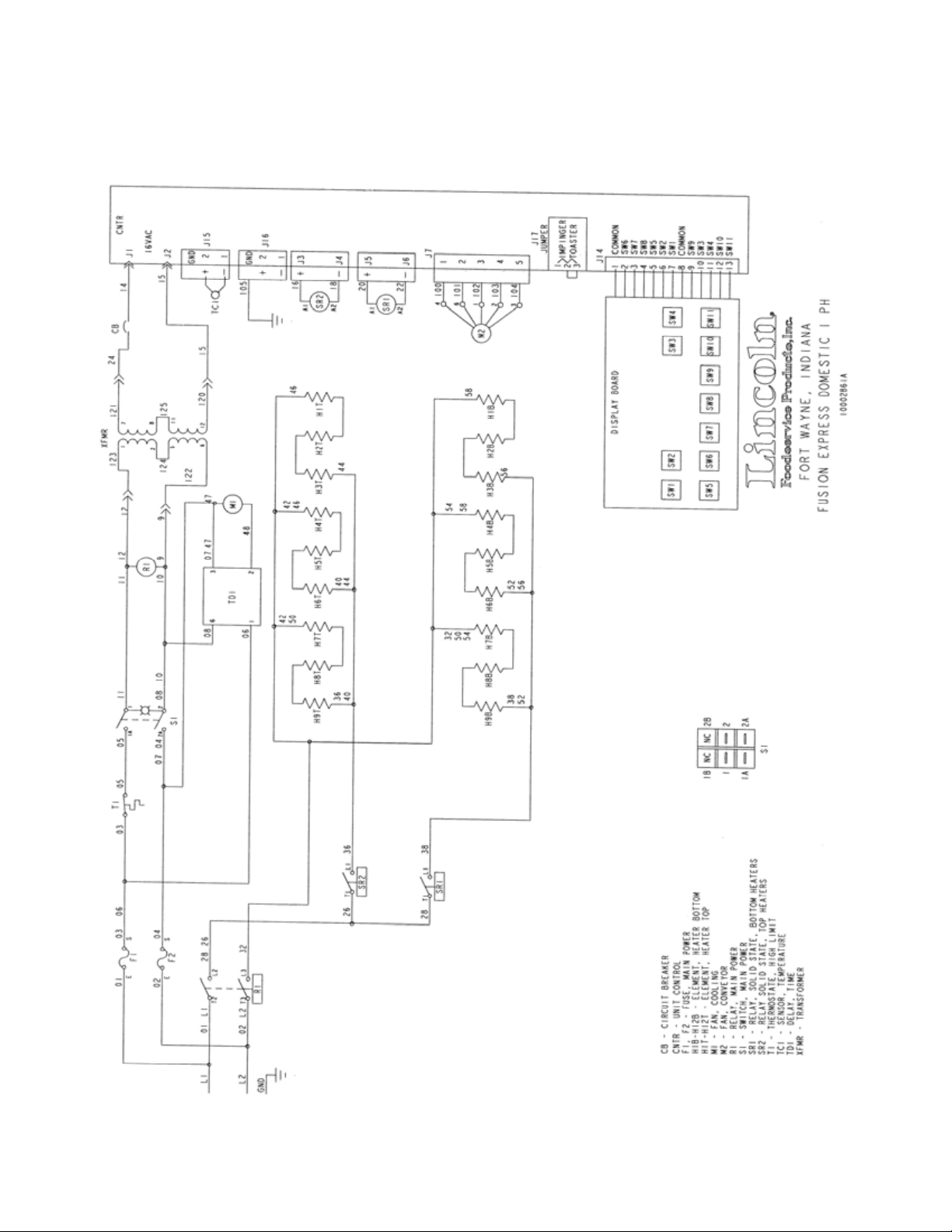
SCHEMATIC – FUSION MODEL: 2030-000-U
208/240V Single Phase Unit - Domestic
Fusion Toaster Series Service Manual
5
Page 6
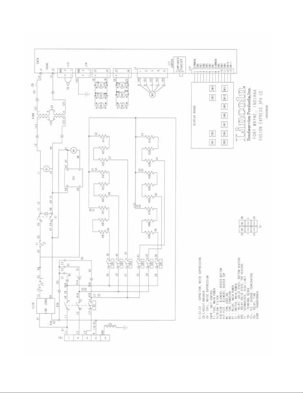
SCHEMATIC – FUSION MODEL: 2032-000-E
208/240V Three Phase Unit - Export
Fusion Toaster Series Service Manual
6
Page 7
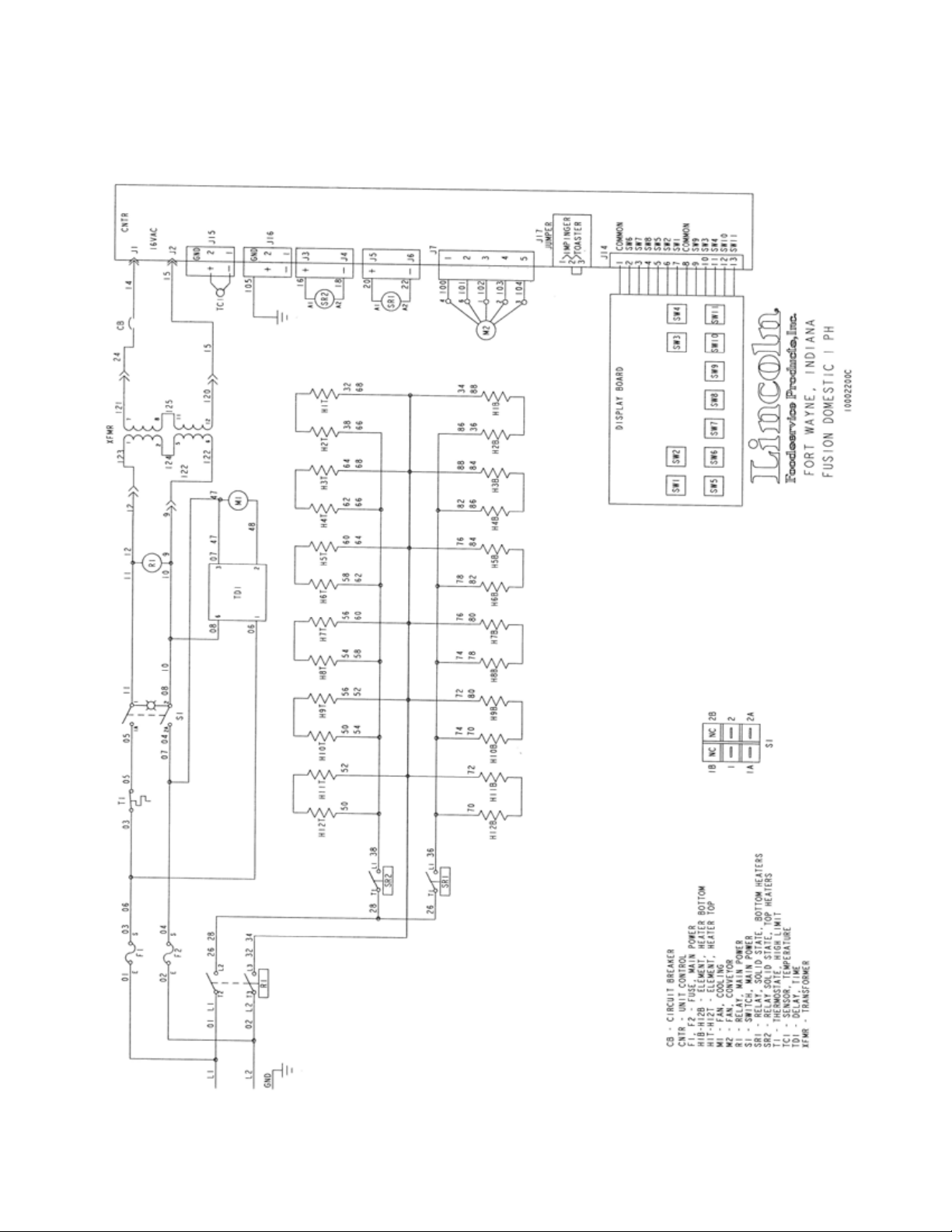
SCHEMATIC – FUSION MODELS: 2040-000-U & 2040-001-U
208/240V Single Phase Unit - Domestic
Fusion Toaster Series Service Manual
7
Page 8
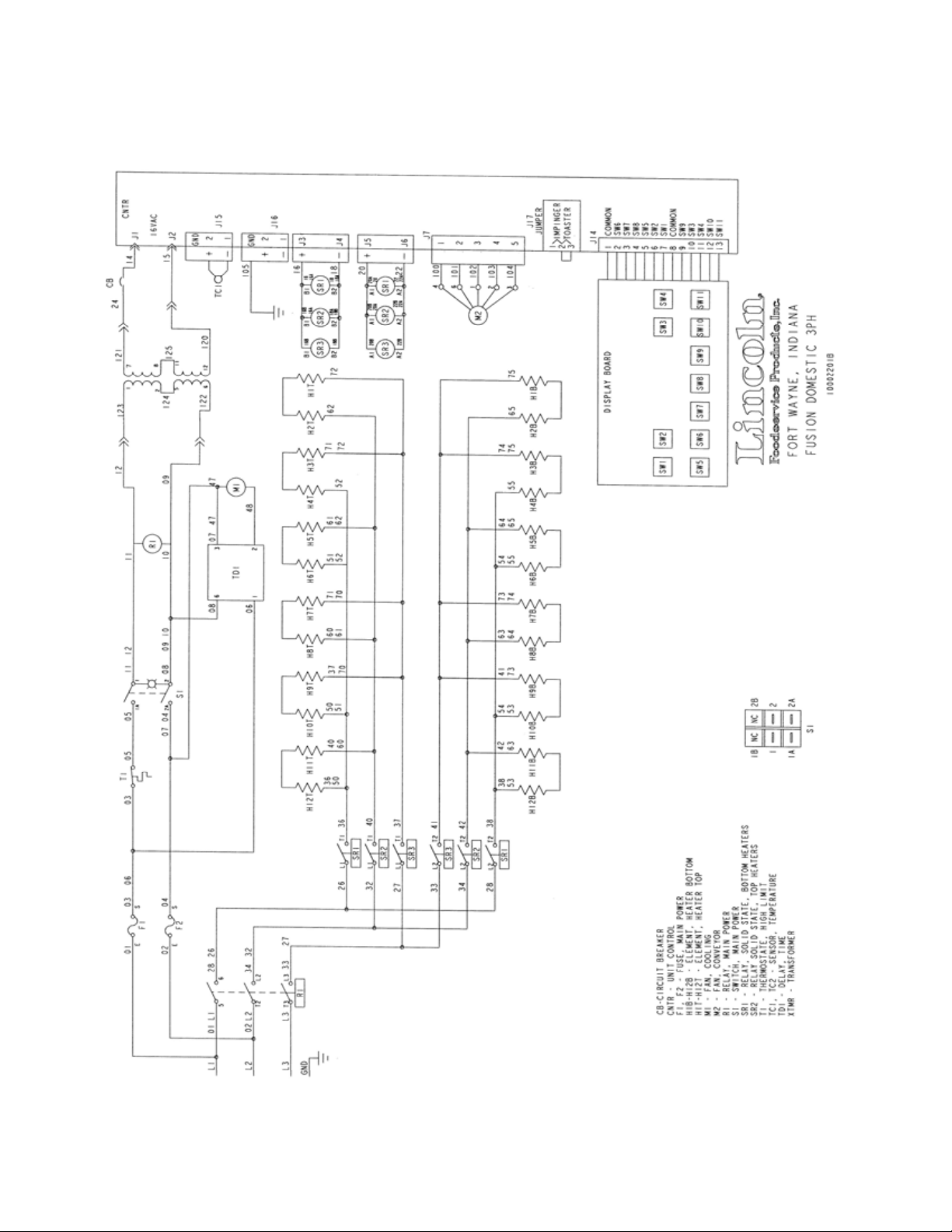
SCHEMATIC – FUSION MODELS: 2041-000-U & 2041-001-U
208/240V Three Phase Unit – Domestic
Fusion Toaster Series Service Manual
8
Page 9
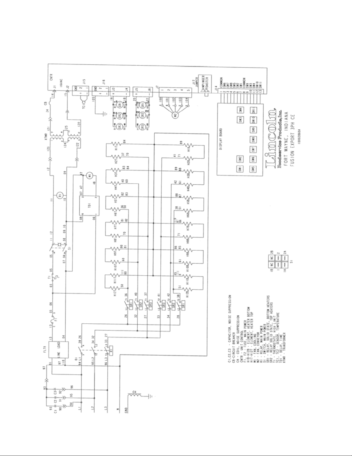
SCHEMATIC – FUSION MODELS: 2042-000-E & 2042-001-E
208/240V Three Phase Unit – Export
Fusion Toaster Series Service Manual
9
Page 10

TROUBLESHOOTING GUIDE
SYMPTOM POSSIBLE CAUSE EVALUATION
Cooling Fan will not run
Oven will not heat
Fusion Toaster Series Service Manual
10
Incoming power supply
Fuse has opened
Incoming power supply
Fuse has opened
Hi-limit thermostat
Control Transformer
Switch Pad
Oven Control
Check power cord to ensure it is
plugged into receptacle. Check
circuit breakers. Reset if required.
Call power company if needed.
Check and replace if necessary.
Check power cord to ensure it is
plugged into receptacle. Check
circuit breakers. Reset if required.
Call power company if needed.
Check and replace if necessary.
Check for voltage on both sides of
thermostat. Terminals are normally
closed. If open, wait for oven to cool
down. Once oven has cooled,
contacts should go back to normally
closed position. If thermostat does
not return to normally closed or will
not hold, replace.
Check for main power to the primary
side of the control transformer. If no
voltage is present, trace wiring back
to main power switch. Check for
secondary voltage off of the
transformer 16~26VAC. If there is
no secondary voltage off of
transformer then replace
transformer.
Check that the switch pad is plugged
into the controller. Ensure all
electrical connections are tight.
Check for supply voltage to control
(16~26 VAC). If no voltage is
present, trace wiring back to
transformer. If control voltage is
present, check display to see that
information is displayed on the
screen. If nothing is displayed on
screen, replace controller. If there is
a read-out on the controller, set the
temperature to the maximum setting
(see operations manual). With the
control at the maximum setting,
check for output voltage (5 VDC) to
the solid state relays. If there is a 5
VDC signal to the solid state relays,
proceed to “solid state relays” for
more troubleshooting information. If
Page 11

there is no voltage to the solid state
relays, trace wiring back to the oven
control. If the wiring is intact and
plugged into the controller then
replace controller.
Solid State Relays
Check for supply voltage to relays (5
VDC) on the low voltage signal side.
If voltage is present and contactor
does not open when heat is called
for then check to ensure that the “+”
and “-“ signal wires have been
connected to the proper terminals on
the relays. If the signal wires are not
correct, place them on the correct
terminal and heaters should
energize accordingly.
Heating Elements
Check the current draw of each
power leg for proper load rating per
the specification plate rating and
operations manual. If the current
draw is outside of limits specified +/10% of rating then proceed to check
each individual element for a failed
condition (e.g. open, shorts, and
proper resistance). Check each
element to ensure that electrical
connection is proper (full torque on
lugs). To check resistance,
elements must be cool and power
disconnected from the elements
(remove all leads from elements and
use a digital multimeter to monitor
electrical resistance). Replace
elements as necessary.
Thermocouple
With power on and thermocouple
attached to the oven control,
measure the DC millivolt output of
the thermocouple. Refer to the
thermocouple chart (located in the
“removal” section of the manual) for
proper millivolt readings. If readings
from the thermocouple do not match
chart in the manual then replace
thermocouple.
Thermocouple
Check to ensure that the
thermocouple is properly secured
into the thermocouple well built into
the heater cartridge. If the
thermocouple is properly secured
into the well but the control indicates
a low temperature when the cavity is
hot then check to ensure that
thermocouple is in the proper
location on the control board and
securely seated in place. If the
Fusion Toaster Series Service Manual
11
Page 12

Conveyor will not run
Incoming power supply
Fuse has opened
Hi-limit thermostat
Switch Pad
Drive Chain
Drive Sprockets
Conveyor Tension
Control Transformer
thermocouple is not in proper place
or electrical connection is not secure
then secure electrical connection. If
electrical connection is good but
thermocouple is still reading
improperly then measure electrical
resistance of thermocouple. The
resistance should be approximately
11 ohms. If this is not the case then
replace thermocouple.
Check power cord to ensure it is
plugged into receptacle. Check
circuit breakers. Reset if required.
Call power company if needed.
Check and replace if necessary
Check for voltage on both sides of
thermostat. Terminals are normally
closed. If open, wait for oven to cool
down. Once oven has cooled,
contacts should go back to normally
closed position. If thermostat does
not return to normally closed or will
not hold, replace.
Check that the switch pad is plugged
into the controller. Ensure all
electrical connections are tight.
Check to ensure that the drive chain
is properly secured to the conveyor
motor and the drive shaft on the
conveyor. If drive chain is not on
drive sprockets then place chain on
sprocket. Check to ensure that the
tension on the drive is sufficient then
adjust conveyor motor to increase
tension. If tension cannot be
adjusted to allow for proper
engagement of sprocket then
replace chain.
Check to ensure that drive sprockets
are secured fastened to drive shaft
on conveyor and conveyor motor
shaft.
Check to ensure that conveyor belt
is under proper tension. If there is
too much tension on belt then adjust
tension through tension screws
located on end of conveyor.
Check for supply voltage to primary
side of the control transformer. If no
Fusion Toaster Series Service Manual
12
Page 13

voltage is present then trace wiring
back to the oven power relay. If
voltage is present then check that
the secondary output of the
16~24VAC. If there is primary
voltage but no secondary voltage
then replace transformer.
Fusion Toaster Series Service Manual
13
Page 14

OPERATING INSTRUCTIONS
!
BELT DIRECTION
BELT SPEED
DANGER!
UP-SCROLL & DOWN-SCROLL
BUTTONS
ENERGY SAVER / POWER DOWN
Do not work around conveyor belt with long hair, loose clothing, or dangling jewelry.
Getting caught in the belt could result in serious injury.
MANUAL PRESET
TEMPERATURE
DISPLAY SCREEN
ON-OFF SWITCH
PROFILE – PRESET BUTTONS
(1 THROUGH 4)
Prior to operating your new Fusion Toaster, it is important to understand the different programmable options
available to you. Following is a chart to better illustrate the different programmable options that are available.
MENU ITEMS DESCRIPTION
Temperature Intensity
Temperature Intensity Balance The Fusion Toaster will allow you to determine where the heat will eman ate. You have the
Belt Speed
Menu Name
POWER-UP TOASTER
1. Turn the “On / Off” Switch to the “ON” position. The green light will illuminate.
Temperature Intensity refers to the temperature in which the unit is toasting. This is shown on
the display board as a unit of measure (low to high) between 0.5 – 10.0.
ability to program your toaster so that more (or less) heat will emanate from the top or bottom of
the toaster. This is shown on the display board as a unit of measure between 5 – 200.
• Display reading between 5 – 95 refers to more top heat / less bottom heat.
• Display reading between 110 – 200 refers to more bottom heat / less top heat.
• Display reading of 100 refers to equal top and bottom heat.
Belt Speed refers to how quickly the food item travels through the toaster. This is shown on the
display board as a unit of measure (fast to slow) between :15 seconds and 5:00 minutes.
Menu Name refers to the names available for programming in the four “Profile-Preset” buttons.
Each menu will be listed on the display as “Menu 1, 2, 3, or 4” which corresponds to the
numbered buttons. The operator has the option of changing these names (see programming
instructions).
ON-OFF SWITCH
Fusion Toaster Series Service Manual
14
Page 15

MENU ITEMS
The Fusion Toaster is equipped with four (4) separate menu items to allow for m ultiple menu settings. These menu
items are shown on the display as ‘Menu 1,’ ‘Menu 2,’ ‘Menu 3,’ or ‘Menu 4’ depending on which menu is selected.
Additionally, these menus can be reprogrammed with a specific food item name such as “sandwich,” “quesadilla,’
“pretzel,” “cookie,” etc. To access each menu, simply press and release the requisite “Profile Preset” button (1
through 4).
PROGRAMMING MENU ITEMS
The Fusion Toaster allows for each of the four saved menu items to be programmed for temperature intensity,
temperature intensity balance, belt speed, and menu name. To program a menu item, follow the steps listed below.
1. Press and hold the “Profile Preset” button you wish to program for approximately 5 seconds. Upon
entering the programming mode, the display will “flash” the temperature intensity setting (a figure between
0.5 & 10.0).
Display
Profile Preset Buttons
2. Press the “”Up-Scroll” or “Down-Scroll” button to change the temperature intensity to desired setting. To
save the setting simply press and release the “Profile Preset” button to advance to the next menu item.
(Notice that in this illustration the menu has been changed from “6.5” to “10.0” which will now “scroll”
through the display.)
Up-Scroll & Down-Scroll Buttons
Fusion Toaster Series Service Manual
15
Page 16

3. After pressing the “Profile Preset” button, the display will “flash” the temperature intensity balance setting (a
figure between 5 & 200).
Display
Profile Preset Buttons
4. Press the “”Up-Scroll” or “Down-Scroll” button to change the temperature intensity balance to desired
setting. (Notice that in this illustration the menu has been changed from “100” to “170” which will now
“scroll” through the display.) To save the setting simply press and release the “Profile Preset” button to
advance to the next menu item.
Up-Scroll & Down-Scroll Buttons
5. After pressing the “Profile Preset” button again, the display will now “flash” the belt speed setting (a figure
between 15 seconds and 5:00 minutes).
Display
Profile Preset Buttons
Fusion Toaster Series Service Manual
16
Page 17

6. Press the “”Up-Scroll” or “Down-Scroll” button to change the belt speed to desired setting. (Notice that in
this illustration the menu has been changed from “15 seconds” to “4 minutes” which will now “scroll”
through the display.) To save the setting simply press and release the “Profile Preset” button to advance to
the next menu item.
Up-Scroll & Down-Scroll Buttons
7. After pressing the “Profile Preset” button again, the display will now “fast-flash” the menu name setting.
Display
Profile Preset Buttons
8. Press the “”Up-Scroll” or “Down-Scroll” button to change the menu name to the desired setting. (Notice
that in this illustration the menu has been changed to “Sandwich,” which will now “scroll” through the
display.) To save the setting simply press and release the “Profile Preset” button. Display will stop flashing
to indicate that programming is complete for this menu item. Repeat these steps to program the remaining
three menu items.
Up-Scroll & Down-Scroll Buttons
Fusion Toaster Series Service Manual
17
Page 18

MANUAL PRESET
The Fusion Toaster also includes a “manual preset” button that allows you to change the toaster configuration
without altering the four programmed menu items. In this “manual preset” mode, you will have the ability to change
the belt speed, temperature intensity, and/or temperature intensity balance. You cannot program or change a
menu name in the manual preset mode.
MANUAL PRESET ADJUSTMENTS
1. Press and release “Manual Preset” button. The menu will flash between the temperature intensity and time
settings.
2. Press and release Temperature button once for Temperature Intensity or twice for Temperature Intensity
Balance.
3. Use the “Up-Scroll” or “Down-Scroll” button to change settings. Press the Temperature button to save the
settings.
Fusion Toaster Series Service Manual
18
Page 19

MANUAL PRESET ADJUSTMENTS (CONT’D)
4. Press and release the “Belt Speed” button.
5. Use the “Up-Scroll” or “Down-Scroll” button to change the belt speed setting.
6. Press and release the “Manual Preset” button. The settings are now operational. Please note that while
you are in the Manual Preset mode and the unit is operating to your programmed settings, the displ ay will
continue to flash between temperature and belt speed.
7. When you wish to return to one of the four menu programs, simply press and release the desired menu
option (1 through 4).
Fusion Toaster Series Service Manual
19
Page 20

ADDITIONAL OPERATION ADJUSTMENT OPTIONS
CONVEYOR DIRECTION
The Fusion Toaster allows for multi-directional (or reversible) travel. If you would prefe r the co nveyor belt to travel
in the opposite direction, simply press and hold the “Belt Direction” button for approximately 5 seconds. The
conveyor belt will change direction momentarily. Note: It is recommended that you wait to change belt direction
until after all food items have completed their pass through the toaster.
ENERGY SAVER OR “SLEEP” MODE
One of the many benefits provided by the Fusion Toaster is its ability to enter into an energy saving “sleep” mode.
1. To enter into “sleep mode,” press and release the “Energy Saver / Power Down” button. Notice that the
small red light appears (and remains lit) next to the Energy Saver button and the conveyor stops moving.
The Fusion Toaster is now operating in “sleep mode.”
2. To release the Fusion Toaster from sleep mode and return to normal operation, press and release the
“Energy Saver” button. You will notice the small red light next to the Energy Saver button begins to flash.
The red light will continue to flash until the toaster returns to the appropriate menu settings. The Fusion
Toaster will be ready for operation once the red light has disappeared. Note: While the toaster is now
operational, it may still take a few minutes to reach peak performance depending on your menu settings.
Red Light
Indicating
Sleep Mode
WARNING:
!
SHUTDOWN
1. Push “On / Off” switch to the “OFF” position.
As each Fusion toaster is equipped with a 30-minute cool-down timer, the fan motor will continue to run for 30-
minutes after the unit has been turned off. The fan motor will automatically stop at the end of the 30-minute cool
down period.
Fusion Toaster Series Service Manual
20
Do not use parchment paper when placing food product through the toaster! Use
of such materials may cause a fire and should never be placed in the toaster.
Page 21

TECHNICIAN MODE
The following information is for use by authorized service technicians only.
When in this mode, technicians will have the ability to set the following parameters:
TECHNICAL MENU ITEMS DESCRIPTION
Temperature Scale
Sleep Mode Power Down %
Exit Sleep Mode Time
Password Protection
In Temperature Scale, the technician will have the ability to set temperature readings in either
°F or °C.
In this mode the technician can set the “Power Down Percentage” to meet the needs of the
end-user. For example, for greater energy savings the end-user may prefer that in Sleep
Mode the toaster operate at 20% of normal operating power output.
This menu allows the technician to set the length of time the red light will flash while toaster
exits sleep mode to enter into normal operation.
If the end-user would prefer the Technician Mode to be password protected to “lock out” the
Technician Mode from employees, the option of password protecting the settings is available.
The password can only be four (4) characters in length.
IMPORTANT: Please note that the greater the percentage difference between
normal operation and sleep mode, the longer the toaster will take to “power up” to
!
the programmed menu settings.
IMPORTANT: This time setting will not necessarily correlate to the toaster
achieving the normal operational menu setting. It is normal for the toaster to
!
require additional time to reach the normal operating menu settings after the red
light stops flashing. In some cases it may take an additional 10-15 minutes
depending on the difference between Sleep Mode Power Do wn Percentage and
normal operating settings.
IMPORTANT: Treat this menu with caution! End user is responsible for
!
remembering their password.
IMPORTANT: Should the customer ever forget their password, the Fusion Toaster
is equipped with a “universal password” for use by the service technician. In the
!
event the customer cannot remember the password, simply insert the word “TECH”
into the display to access the Technician Mode. Note, the original password will
remain active until another password is selected.
1. Press the “Up-Scroll” AND “Down-Scroll” buttons at the same time for approximately 5 seconds. The menu
will flash “DEGF.” Press the “Up-Scroll” or “Down-Scroll” to change the setting between °F and °C.
Fusion Toaster Series Service Manual
21
Page 22

2. Press and release the Temperature button to access the “Sleep Mode Power Down %.” The menu will
flash a number that corresponds to the percentage of energy consumption compared to normal operation .
Press the “Up-Scroll” or “Down-Scroll” button to reach the desired sleep mode energy consumption setting.
See “Sleep Mode Power Down %” description in the previous table for an important warning notice.
3. Press and release the Clock button. The menu will flash a time setting that corresponds to the length of
time the red light will flash while exiting the sleep mode. See “Exit Sleep Mode Time” description in the
previous table for an important warning notice.
4. Press and release the Clock button. The menu will scroll “PASSWORD OFF.” Use the “Up-Scroll” or
“Down-Scroll” button to change to/from “PASSWORD OFF”/”PASSWORD ON.”
Fusion Toaster Series Service Manual
22
Page 23

5. After you have turned on the password feature, press the Temperature button to set the desired password.
After pressing the Temperature button to set a password, the display will read “XXXX” with the first
character flashing.
6. Press the “Up-Scroll” or “Down-Scroll” button to locate the desired alpha-numeric character. Once the
desired character has been selected, press the Temperature button to move to the next character. Perform
the same operation to set each of the four characters. If at any time you wish to move back to a previous
character, simply press the Clock button.
7. Once the password characters have been selected, press the Temperature button again to save the
password into memory. BE SURE THE CUSTOMER RETAINS THEIR PASSWORD IN A SAFE PLACE.
8. Press one of the Profile Preset buttons to exit out of Technician Mode.
Fusion Toaster Series Service Manual
23
Page 24

GENERAL VIEW – 2030 SERIES
LETTER PART NUMBER DESCRIPTION
A 370729 Front Panel Assembly, Outside
B 370731 I.R. Element Assembly, Lower
C 370730 I.R. Element Assembly, Upper
D 370733 Fuse Cover
370734 Fuse, 10A Model 2030-000-U Domestic Unit Only
E
F 370735 Cover, Top
G 370736 Thermostat
H 370737 Heater Element Clamp
I 370738 Back Panel Assembly, Outside
J
K 370364 Ground Lug
L
M 370743 Guard Chain, Interior
N 370744 Motor Mounting Plate
P 370745 Toaster Gear Sprocket
R 370746 Conveyor Motor
S 370747 Chain Cover Assembly
T 370748 Toaster Cordset
V 370749 Strain Relief
W 370750 Enter / Exit Tray
X 370751 Conveyor Assembly
Y 370732 Transformer
Z 370752 Fan, AC
AA 370753 Cover, Bottom
BB 370754 Finger Guard, Fan
CC 370767 Circuit Breaker
DD 370755 Leg, Black
EE 370466 Time Delay Module, 230 Volt
FF
GG 370758 Membrane Switch
HH 27511SP Lighted Rocker Switch
Not Shown 370759 Stacking Bracket
Not Shown 370540 Solid Ferrite Assembly, Model 2030-000-E Export Unit Only
Not Shown 370180 EMI Filter, Model 2030-000-E Export Unit Only
Not Shown 370760 Thermocouple
Not Shown 370761 Wire Harness, Base (Domestic)
Not Shown 370762 Element Harness, 1-Phase (Domestic)
Not Shown 370763 Transformer Harness (Domestic)
Not Shown 370764 Wire Harness, Base (Export)
Not Shown 370765 Element Harness, 3-Phase (Export)
Not Shown 370766 Transformer Harness (Export)
369492 Fuse, 5A Model 2030-000-E Export Unit Only
369129 Fuse Holder, Model 2030-000-U Domestic Unit Only
370342 Fuse Holder, Model 2030-000-E Export Unit Only
370739 Contactor
370740 Contactor Rail
370741 Solid State Relays, Model 2030-000-U Domestic Unit Only
370742 Solid State Relays, Model 2030-000-E Export Unit Only
370756 Controller
370757 Controller Bracket
Fusion Toaster Series Service Manual
24
Page 25

GENERAL VIEW – 2030 SERIES
Fusion Toaster Series Service Manual
25
Page 26

GENERAL VIEW – 2040 SERIES
LETTER PART NUMBER DESCRIPTION
A 370778 Front Panel Assembly, Outside
B 370779 Membrane Switch
C 370780 I.R. Element Assembly, Lower
D 370781 I.R. Element Assembly, Upper
E 370782 Conveyor Assembly
F 370180 EMI Filter (Export Units Only)
G 370784 Fuse Cover
370734 Fuse, 1A (Domestic)
H
I 370785 Cover, Top
J 370736 Thermostat
K 370786 Heater Element Clamp
L
M 370787 Back Panel Assembly, Outside
N
O 370364 Ground Lug
P 370743 Chain Guard, Interior
R 370744 Motor Mounting Plate
S 370745 Toaster Gear Sprocket
T 370788 Conveyor Motor
U
W 370747 Chain Cover Assembly
X
Y 370795 Enter / Exit Tray
Z 370732 Transformer
AA 370796 Fan, AC
BB 370797 Cover, Bottom
CC 370798 Fan Finger Guard
DD 370767 Circuit Breaker
EE 369303 Snap Bushing
FF 370755 Leg, Black
GG 370466 Time Delay Module, 230 Volt
HH 370756 Controller
JJ 370757 Controller Bracket
KK 27511SP Lighted Rocker Switch
Not Shown 370799 Stacking Bracket
Not Shown 370540 Solid Ferrite Assembly
Not Shown 370761 Wire Harness, Base (Domestic)
Not Shown 370763 Transformer Harness (Domestic)
Not Shown 370800 Element Harness, 1-Phase (Domestic)
Not Shown 370801 Element Harness, 3-Phase (Domestic)
Not Shown 370764 Wire Harness, Base (Export)
Not Shown 370802 Element Harness, 3-Phase (Export)
Not Shown 370766 Transformer Harness (Export)
Not Shown 370760 Thermocouple
369129 Fuse Holder (Domestic)
369492 Fuse, 1A (Export)
370342 Fuse Holder (Export)
370741 Solid State Relay, 1-Phase
370742 Solid State Relay, 3-Phase
370739 Contactor
370740 Contactor, Rail
370789 Power Cord Assembly, 1-Phase
370790 Power Cord Assembly, 1-Phase (-001- models)
370791 Power Cord Assembly, 3-Phase
370792 Power Cord Assembly, 3-Phase (-001- models)
370793 Strain Relief, 1-Phase (Domestic)
370794 Strain Relief, 3-Phase (Domestic)
370749 Strain Relief, 3-Phase (Export)
Fusion Toaster Series Service Manual
26
Page 27

GENERAL VIEW – 2040 SERIES
Fusion Toaster Series Service Manual
27
Page 28

CONVEYOR VIEW – 2030 SERIES
LETTER PART NUMBER DESCRIPTION
10001377 Complete Conveyor Assembly
A 370481 DTF, Flanged Bearing
B 370768 Conveyor Shaft, Idler
C 370769 Sprocket, Idler
D 370770 Wldmt, Bushing, Shaft
E 370771 Wire Belt Assembly
F 370772 Splice Clip
G 370773 Middle Crumb Tray
H 370745 Toaster Gear Sprocket
I 370774 Wldmt, Bushing, Shaft
J 370775 Conveyor Shaft, Drive
K 370776 Drive Sprocket
L 370777 Outer Crumb Tray
M 10001380 Tray Support Bracket
Fusion Toaster Series Service Manual
28
Page 29

CONVEYOR VIEW – 2040 SERIES
LETTER PART NUMBER DESCRIPTION
10000907-01
10000907-02
A 370481 DTF, Flanged Bearing
B 370803 Conveyor Shaft, Idler
C 370804 Sprocket, Idler
D 370770 Wldmt, Bushing, Shaft
E 370806 Wire Belt Assembly
F 370808 Splice Clip
G 370805 Middle Crumb Tray
H 370745 Toaster Gear Sprocket
I 370774 Wldmt, Bushing, Shaft
J 370807 Conveyor Shaft, Drive
K 370776 Drive Sprocket
L 370809 Outer Crumb Tray
M 10000864-01 Tray Support Bracket
Complete Conveyor Assembly
Models 2040-000-U, 2041-000-U, 2042-000-E
Complete Conveyor Assembly
Models 2040-001-U, 2041-001-U, 2042-001-E
Fusion Toaster Series Service Manual
29
Page 30

Lincoln Foodservice Products, LLC
1111 North Hadley Road
Fort Wayne, Indiana 46804
United States of America
Telephone: (260) 459-8200
U.S. Fax: (888) 790-8193 • Int’l Fax: (260) 436-0735
Technical Service Hot Line
(800) 678-9511
www.lincolnfp.com
Fusion Toaster Series Service Manual
30
 Loading...