

LightSpeed Technologies Redcat User Manual
Classroom Audio System
User Manual
REDCAT User Manual
REDCAT User Manual | i
REDCAT User Manual
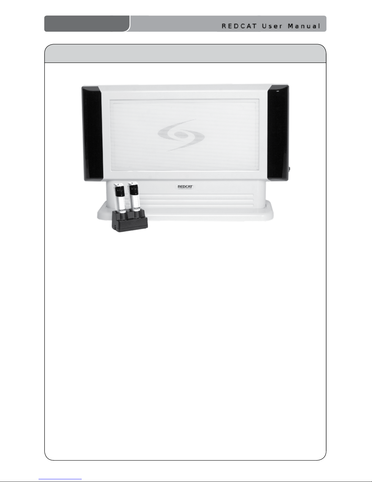
CONGRATULATIONS!
Congratulations on your purchase of the REDCAT™ All-in-One
Classroom Audio System! This simple, yet powerful technology provides
crystal-clear sound throughout the classroom, allowing every child to hear
every word every time.
As the teacher speaks into the REDMIKE™ classroom microphone, his or
her voice is transmitted to the REDCAT and then amplied through the
built-in at panel speaker. The REDCAT system is fully integrated and
includes a receiver/amplier, infrared sensors, at panel speaker and the
REDMIKE classroom microphone.
The REDCAT is a two-channel receiver/amplier that allows the use of up
to two microphones simultaneously and two audio input sources such as
TV, VCR, DVD, CD, MP3, etc.
The REDMIKE is an infrared classroom microphone. This pendant-style
microphone is clipped to a lavaliere cord and worn around the teacher’s
neck. It can also be used as a standard handheld microphone for student
interaction and class participation.
REDCAT User Manual
ii | REDCAT User Manual
REDCAT User Manual
1. Read Instructions—All the safety
and operation instructions should be
read before this Lightspeed product is
operated.
2. Retain Instructions—The safety and
operating instructions should be kept
for future reference.
3. Heed Warning—All warnings on this
Lightspeed product and in these
instructions should be followed.
4. Follow Instructions—All operating
and other instructions should
be followed.
5. Water and Moisture—This
Lightspeed product should not be
used near water.
6. Heat—This Lightspeed product should
be situated away from heat sources
such as radiators, etc.
7. Power Sources—This Lightspeed
product should be connected to
a power supply only of the type
described in the operation
instructions or as marked on this
Lightspeed product.
8. Power Cord Protection—Power
supply cords should be routed so that
they are not likely to be walked upon
or pinched by items placed upon or
against them.
9. Object and Liquid Entry—Care should
be taken so that objects do not fall
onto and liquids are not spilled into
the Lightspeed product.
10. Damage Requiring Service—This
Lightspeed product should be serviced
only by qualied service personnel.
The user should not attempt to service
this Lightspeed product.
11. Prevent Electric Shock—Do not use
this polarized plug with an extension
cord, receptacle or other outlet unless
the blades can be fully inserted to
prevent blade exposure.
SAFETY INSTRUCTIONS AND CERTIFICATIONS
CAUTION: TO REDUCE THE RISK OF ELECTRIC SHOCK
DO NOT REMOVE COVER (OR BACK)
NO USER-SERVICEABLE PARTS INSIDE
REFER SERVICING TO QUALIFIED PERSONNEL
RISK OF ELECTRIC SHOCK DO NOT OPEN
The lightning ash with arrowhead symbol
within an equilateral triangle is intended to
alert the user to the presence of uninsulated
“dangerous voltage” within the product’s
enclosure, that may be sufcient magnitude to
constitute a risk of electric shock.
The exclamation point within an equilateral
triangle is intended to alert the user to
the presence of important operating and
maintenance (servicing) instructions in the
literature accompanying the appliance.
Complies with 72/23/EEC Low Voltage Directive
and 89/336/EEC Electromagnetic Compatibility
Directive. Compliance was demonstrated to the
following specications as listed in the Ofcial
Journal of the European Union:
EN 60950: Electrical Safety – A1:1993,
A2:1993, A3:1993, A4:1997
EN 55022: RF Emissions, Information
Technology Equipment
EN 55024: EMC Immunity Standard
EN 61000-3-2: Harmonics
EN 61000-3-3: Voltage Fluctuation
Lightspeed Technologies launched a formal
product recycle program in Europe that
complies with the European Union Directive
2002/96/EC on Waste Electrical and Electronic
Equipment (“WEEE Directive”). Please visit our
website at www.lightspeed-tek.com for more
information.
REDCAT is manufactured using lead-free
processes and is free of other materials
harmful to the environment. It conforms to the
most stringent new European guidelines for
consumer products (RoHS).
CAUTION
CERTIFICATIONS

REDCAT User Manual
REDCAT User Manual | iii
REDCAT User Manual
TABLE OF CONTENTS
REDCAT CLASSROOM AUDIO SYSTEM
Safety Instructions and Certications ........................................................................ii
SECTION 1: System Overview ................................................................................. 1
System Components ............................................................................................. 2
Side Panel Controls and Connections .................................................................... 3
Rear Panel Controls and Connections .................................................................... 4
REDMIKE Controls and Connections ...................................................................... 5
Attaching the Lanyard to REDMIKE ........................................................................ 6
Cradle Charger Controls and Connections ............................................................. 7
Optional LT-71 LightMic Controls and Connections ................................................ 8
Optional HM-70 Handheld Controls and Connections ............................................ 9
SECTION 2: Set-up ..................................................................................................10
Unpacking Your System ........................................................................................11
Determine Set-up Method ....................................................................................12
Tabletop Set-up ....................................................................................................12
Wall-mount Set-up ................................................................................................13
Remove the Base/Wall Bracket .............................................................................13
Mount Base/Wall Bracket ......................................................................................14
Audio Integration ..................................................................................................15
Connectiong External Audio Sources ................................................................... 16
Connecting the Power Supply ...............................................................................
17
Final Check ...........................................................................................................17
SECTION 3: System Operation and Optional Features .........................................18
Initial Set-Up: REDMIKE ........................................................................................19
Initial Set-Up: Optional LT-71 ................................................................................20
Initial Set-Up: Optional HM-70 ..............................................................................21
Charging the REDMIKE .........................................................................................22
Charging the Optional LT-71 .................................................................................23
Charging the Optional HM-70 ...............................................................................24
Output to assistive listening device (ALD) ............................................................25
Using the REDMIKE to Amplify External Audio Equipment ....................................26
SECTION 4: Troubleshooting, Daily Use and Warranty.........................................27
Troubleshooting Guide ..........................................................................................28
Daily Use Instructions ...........................................................................................29
Tips on Classroom Audio ......................................................................................30
Warranty Statement .............................................................................................30
System Specications ..........................................................................................31
Individual Components and Optional Accessories ................................................32
User Notes ...............................................................................................................33

REDCAT User Manual
1 | REDCAT User Manual
SECTION 1
System Overview
REDCAT User Manual
REDCAT User Manual | 2
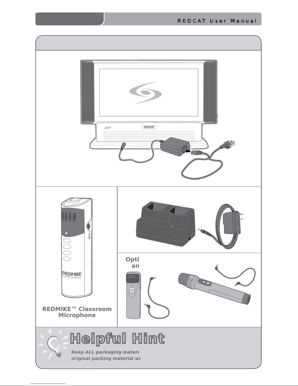
SYSTEM COMPONENTS
Keep ALL packaging materials. If the system must be returned, using the
original packing material will be quick, convenient and prevent damage.
REDMIKE™ Classroom
Microphone
Optional LT-71 LightMic
and Charging Cable
Optional HM-70
Handheld Microphone
and Charging Cable
Charging Cradle and Power Supply
LT -71
Helpful Hint
REDCAT™ Infrared Receiver/Amplier
w/Table Stand and Power Supply
REDCAT User Manual
3 | REDCAT User Manual
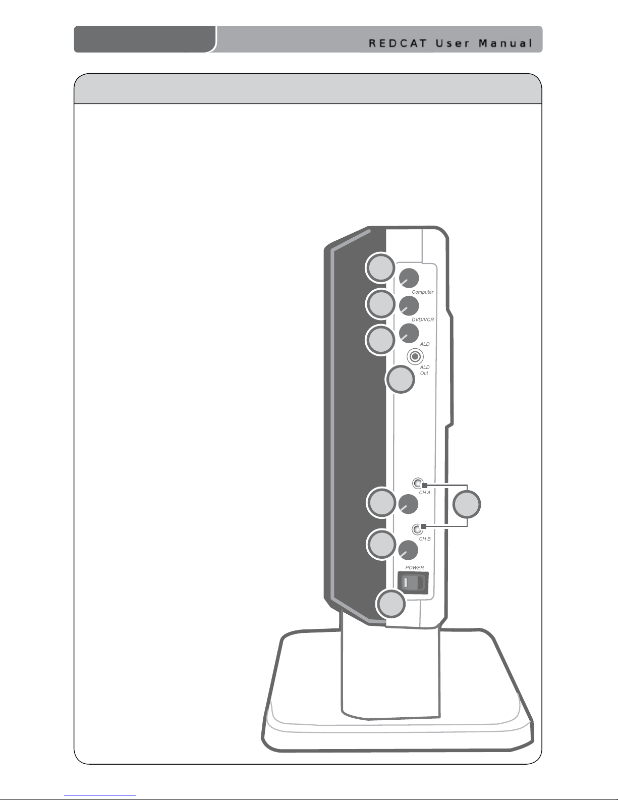
1. COMPUTER VOLUME: Controls the volume level of the audio input from a
computer or other device connected to the “computer” input. Rotating the knob
clockwise increases volume level.
2. DVD/VCR VOLUME: Controls the volume level of the audio input from a DVD/VCR
or other device connected to the “DVD/VCR” input. Rotating the knob clockwise
increases volume level.
3. ALD VOLUME: Controls the volume level
of the audio output to an assisted
listening device (ALD). Rotating the
knob clockwise increases volume level.
4. ALD OUT: 3.5mm output to an ALD
or recording device.
5. A VOLUME: Controls the volume
level of the microphone set to
Channel A. Rotating the knob
clockwise increases volume level.
6. B VOLUME: Controls the volume
level of the microphone set to
Channel B. Rotating the knob
clockwise increases volume level.
7. POWER Switch/Indicator: This
switch is used to turn the REDCAT
ON or OFF. The POWER light will
glow RED when the system is on.
8. IR Indicators: These lights will
glow RED when the corresponding
microphone is turned on. A steady
light conrms the REDCAT is receiving
a strong infrared signal.
SIDE PANEL CONTROLS AND CONNECTIONS
1
2
3
4
6
5
7
8
REDCAT User Manual
REDCAT User Manual | 4
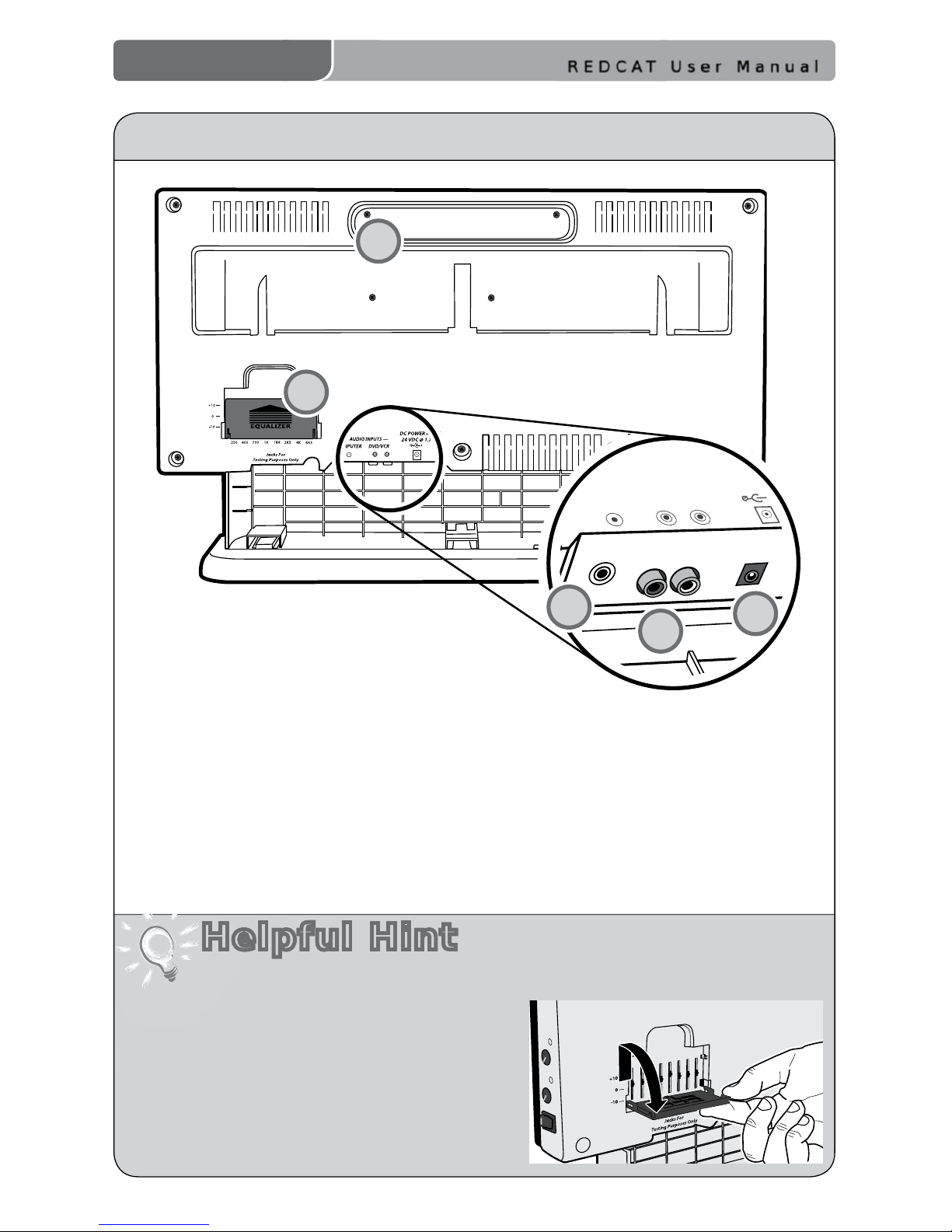
REAR PANEL CONTROLS AND CONNECTIONS
1
2
Helpful Hint
— AUDIO INPUTS —
COMPUTER DVD/VCR
DC POWER INPUT
24VDC @ 1.75A
5
3
4
1. CARRYING INSET: Cutaway grip for
moving or carrying the REDCAT.
2. 8-BAND GRAPHIC EQUALIZER: The sliding
controls adjust the levels of the various audio
frequencies. This allows the installer to properly equalize the system to
produce optimum sound quality.
3. COMPUTER AUDIO INPUT: Plug the 3.5mm cord from computer or other
audio source into this jack.
4. DVD/VCR AUDIO INPUT: Plug the RCA stereo cord from any DVD or VCR into
this mono input jack.
5. DC INPUT: Plug the power supply (24 V/1.75 A) into this jack.
Before adjusting the graphic equalizer refer to the intial set-up on page 18. Sometimes
ne-tuning is required to eliminate feedback.
Fine-tuning the Graphic Equalizer:
1. Slide
up and ip down the EQ cover door.
2. Walk the room listening for feedback
(squealing).
3. Lower the 2K5 and/or 4K sliders if a high-
pitched ring is present.
4. Lower the 400 and/or 700 sliders if a low-
pitched ring is present.
5. Reduce volume if feedback is still present.
REDCAT User Manual
5 | REDCAT User Manual
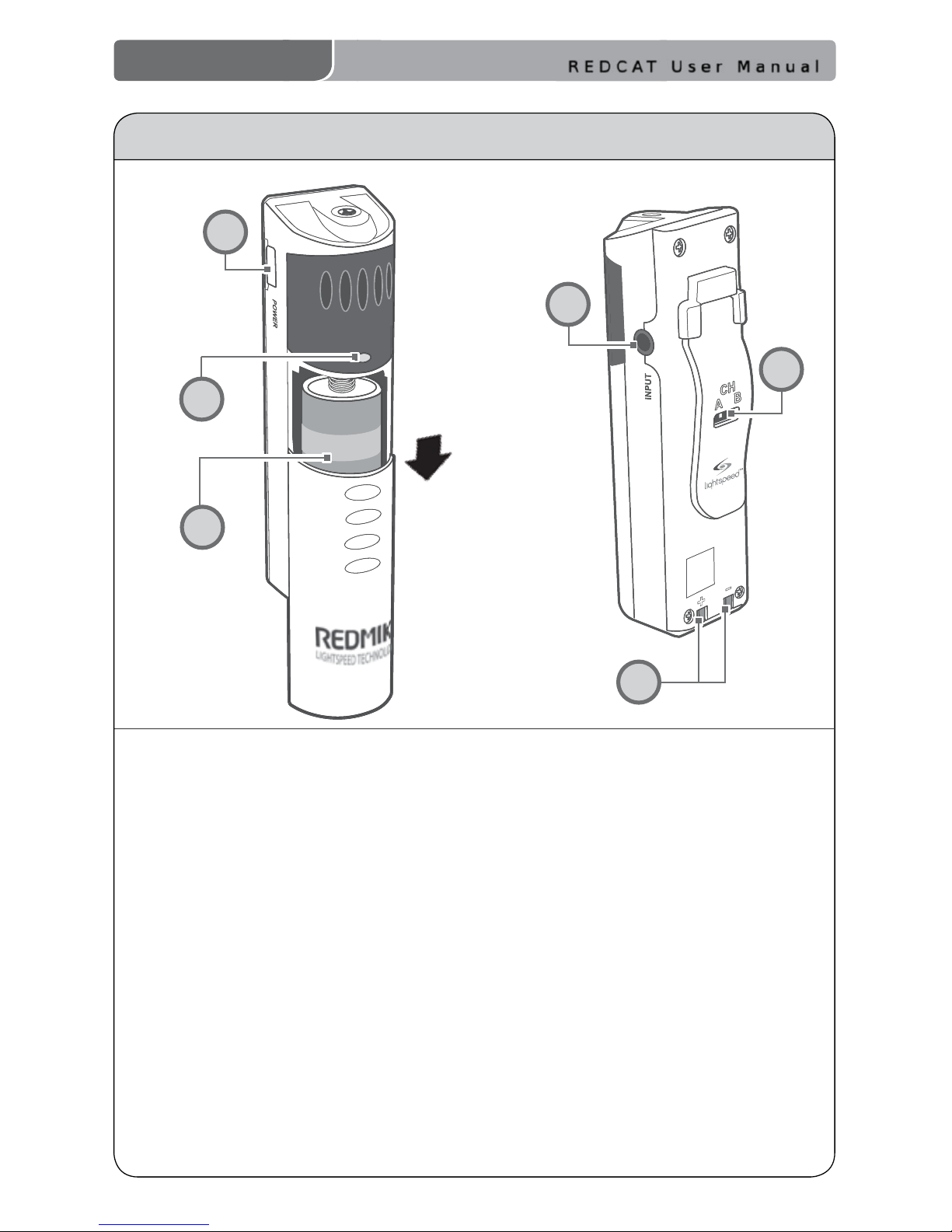
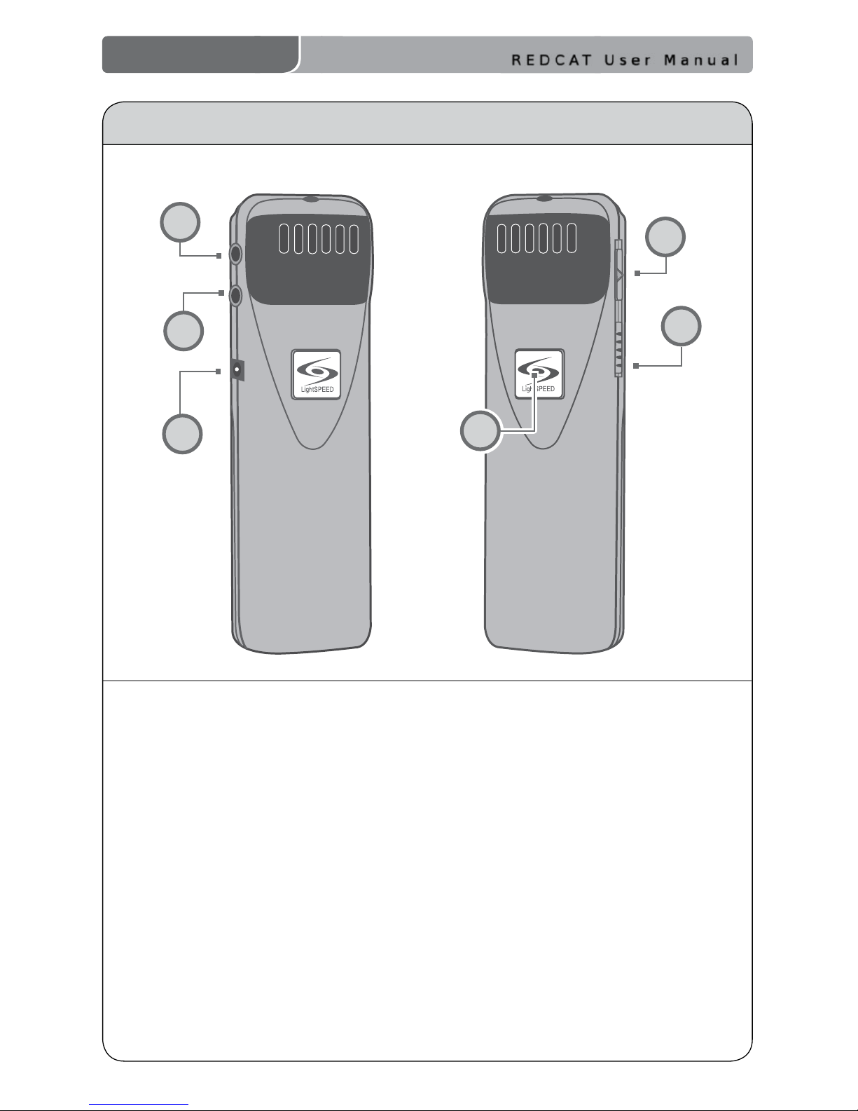
1. POWER BUTTON: Press this button
to turn the REDMIKE ON, press
again to turn it OFF (mute).
2.
POWER/LOW BATTERY INDICATOR:
A BLUE light indicates the REDMIKE
is on and fully charged. A RED light
indicates a charge is needed.
3.
BATTERY COMPARTMENT: To
access the battery compartment,
slide the door downward.
The battery should only be
replaced by a Lightspeed AA
rechargeable sensing battery
(part # BA-NH2A27).
4. AUDIO/MICROPHONE INPUT: Use this
input to plug in a laptop, MP3 player
or other audio source to wirelessly
transmit audio to be played through
the system. Alternatively, an external
microphone can be connected.
5.
CHANNEL SELECT SWITCH (CH A/B):
This switch allows for selection between
Channel A or B. If you are using a single
microphone, we recommend using
Channel A.
6.
CHARGER CONTACTS (+ -): These
contacts interface with the charging
tabs in the BC-RMCC cradle charger
for daily charging. Simply place the
REDMIKE in the charger.
REDMIKE CONTROLS AND CONNECTIONS
1
2
3
4
5
6
REDCAT User Manual
REDCAT User Manual | 6
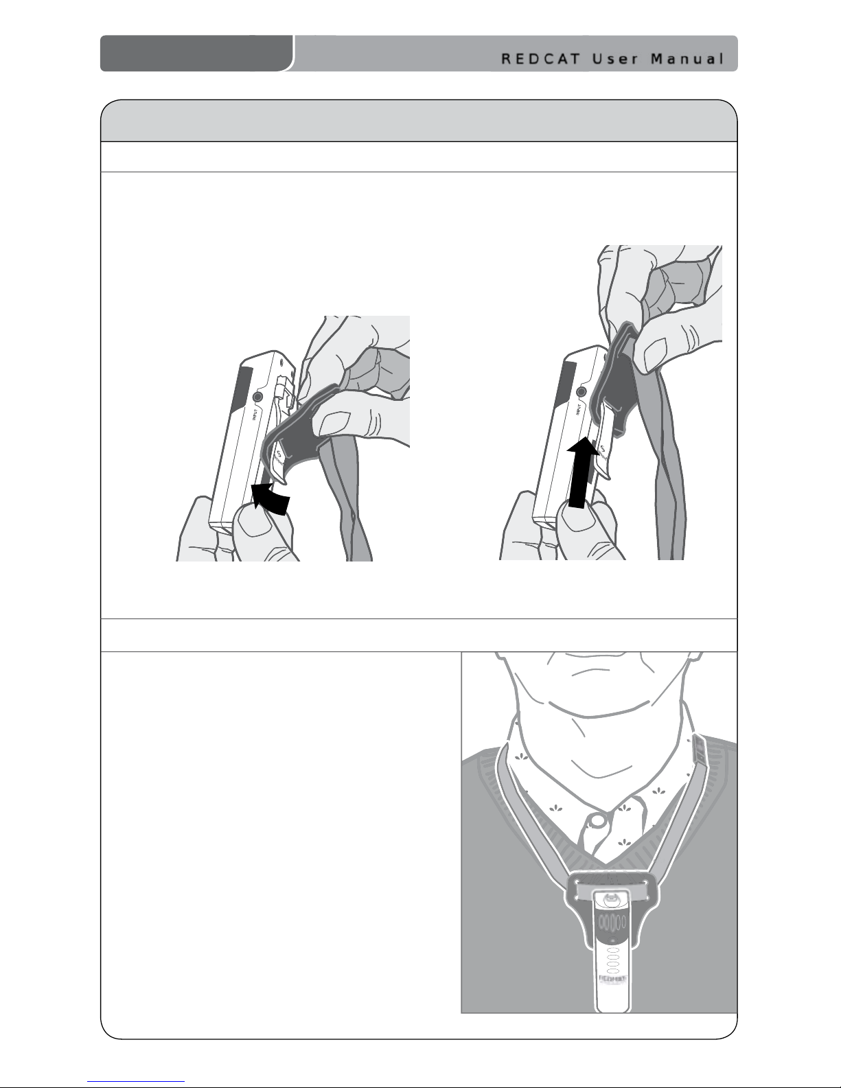
1. ATTACH THE FOAM HOLDER
Insert the REDMIKE clip into the slot
at the bottom of the foam holder.
ATTACHING THE LANYARD TO REDMIKE
2. POSITION THE REDMIKE
Slip the REDMIKE with lanyard
around the neck. Adjust the neck
strap so the top of the microphone
rests just below your collarbone.
REDCAT User Manual
7 | REDCAT User Manual
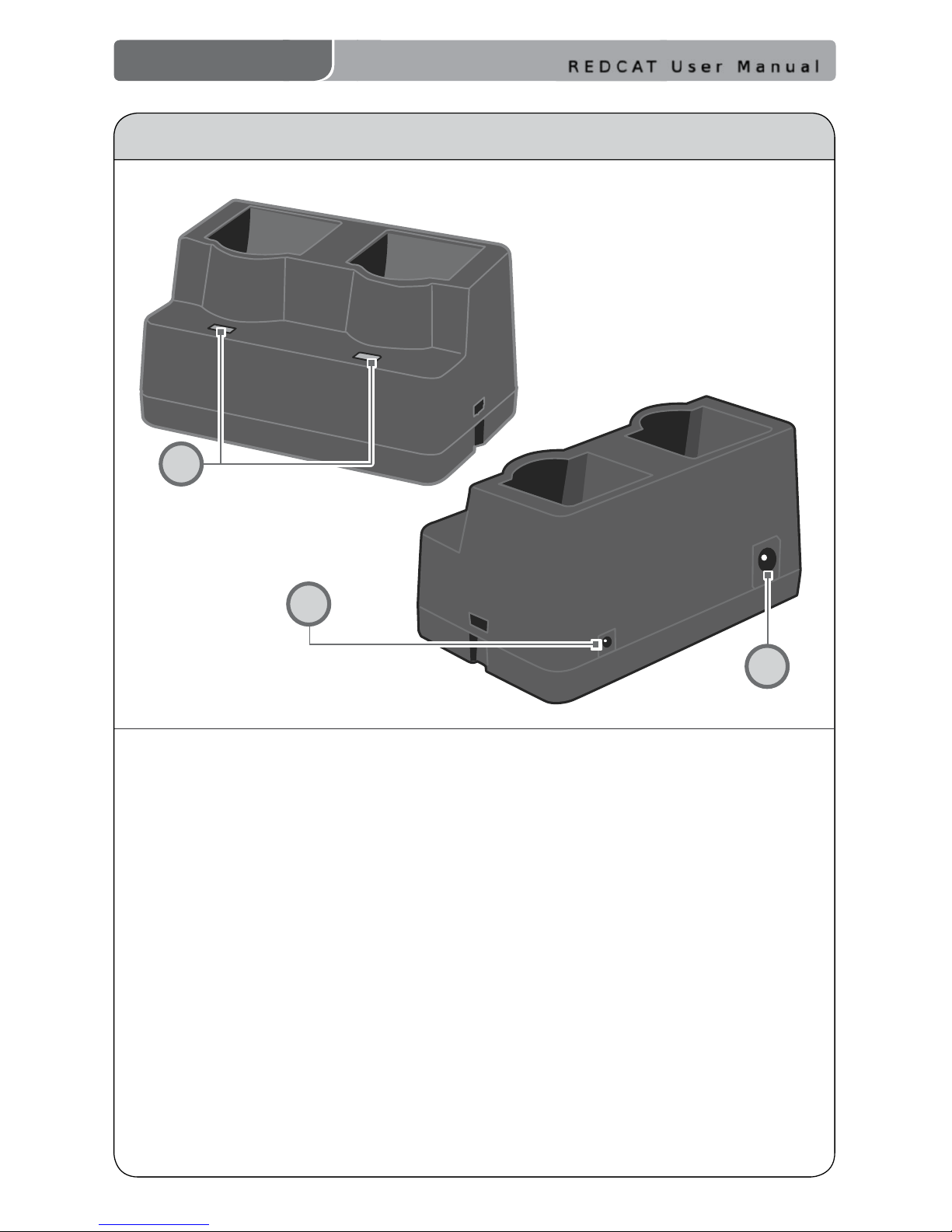
CRADLE CHARGER CONTROLS AND CONNECTIONS
1
2
3
1. CHARGE INDICATORS: The light
glows RED while the REDMIKE is
charging. When fully charged, the
light will glow GREEN. A blinking
RED light indicates that no battery
is sensed, (paper insulator may not
have been completely removed.)
A blinking Green LED means a
non- Lightspeed battery has been
installed (possibly an alkaline
battery).
2.
DC POWER PORT: Connect the DC
power cord here.
3.
OPTIONAL CHARGING PORT: Plug the
charging cord for the optional LT-71 or
the HM-70 microphones here.
REDCAT User Manual
REDCAT User Manual | 8
1. ON/OFF/MUTE Switch: This switch
turns LT-71 ON or OFF (mute).
2.
Channel Select Switch (CH A/B):
This switch allows for selection
of Channel A or B. If you are
using a single microphone, we
recommend using Channel A.
3.
Power/Charge Indicator: The
light glows BLUE when the LT-71
is powered ON, RED when being
charged.
4.
External Microphone Input (MIC):
Use the 3.5mm MIC jack for the
optional TK-250 headset microphone
(part# MC-TK250LTM).
5.
Auxiliary (AUX): Plug a laptop, MP3
player or other audio source into
this jack to wirelessly transmit the
audio signal to be played through
the system.
6.
Charger Input (CHARGER): Plug
the charging cable from the
charger into this jack for daily
charging. The LED on the front will
glow RED to indicate charging.
OPTIONAL LT-71 LIGHTMIC CONTROLS AND CONNECTIONS
LT- 71
LT- 71
1
2
4
5
6
3
REDCAT User Manual
9 | REDCAT User Manual
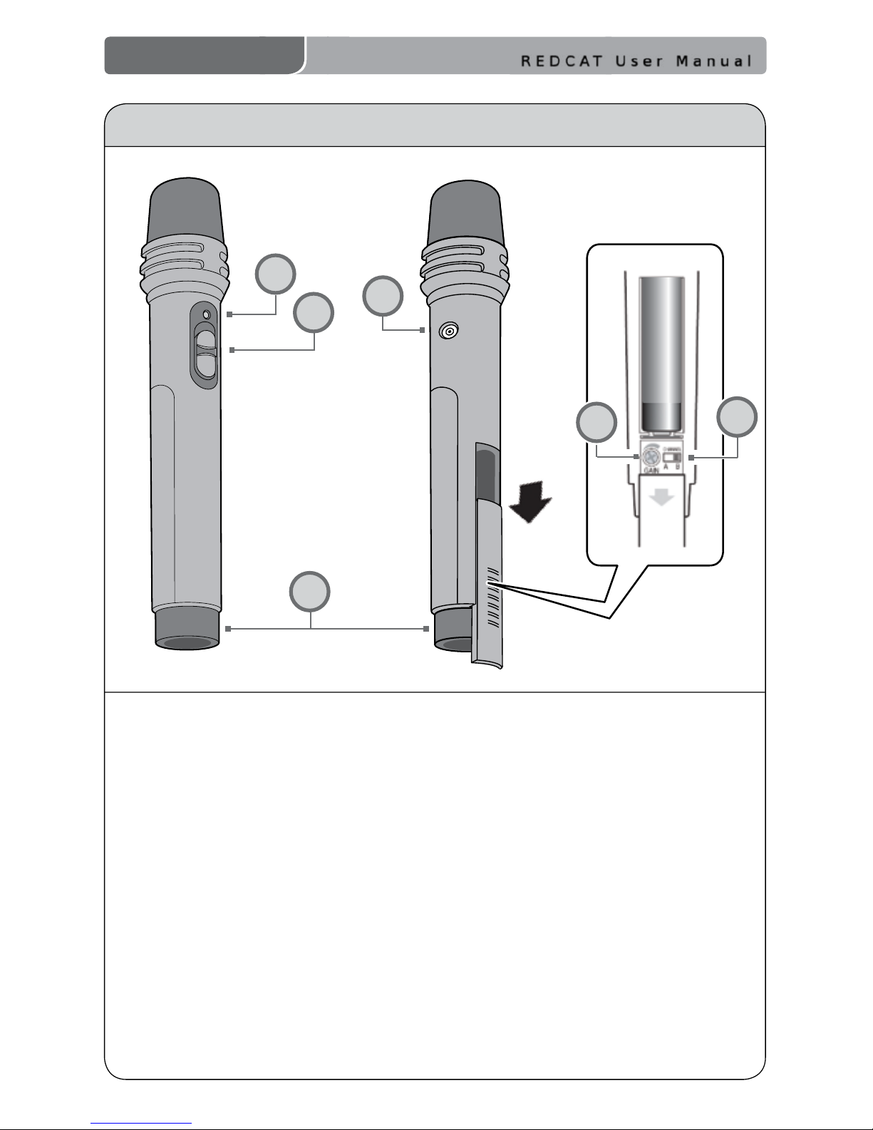
OPTIONAL HM-70 HANDHELD CONTROLS AND CONNECTIONS
1
5
3
4
1. ON/OFF/MUTE Switch: This switch
turns the unit ON, OFF or MUTE.
2.
Channel Select Switch (CH A/B):
Located in the battery compartment,
the switch is set to Channel B at
the factory.
3.
Power/Charge Indicator: The
light glows RED when the HM-70
is powered ON, GREEN when
charging.
4.
Charger Input (CHARGER): Plug
the charging cable from the charger
into this jack for daily charging.
5.
Infrared Emitters: Avoid covering
the emitters as you grip the HM-70
as this could interrupt signal
transmission from the microphone.
6.
Volume Gain Adjustment:
Optimum volume level is
pre-set at the factory and no
adjustment should be necessary.
6
2
NiMH
 Loading...