

Page 1

LES 600 Series
Listening Enhancement System
for Sound-Field Classroom Amplification
tm
User Manual
LightSPEED Technologies, Inc.
Page 2
Table of Contents
Several studies validated by the U.S.
Department of Education and the
Educational Audiology Association verify that
poor classroom acoustics, high ambient noise,
and temporary mild hearing loss among children
place many students academically at risk.
The Sound-Field FM Classroom Amplification
provided by the LES 600 increases both the
volume and clarity of your voice, and evenly
distributes it so that no matter where students
are seated, they have equal opportunity to
understand what is being said, regardless of
seating arrangement.
The following pages provide: Pages
Operating Instructions 4
Microphone Placement 7
Connecting to Other Audio Equipment 10
Tips on Using Classroom Amplification 12
Reference Guide to Controls 14
Trouble Shooting 18
Transmitter and Battery Care 20
Now we hope you will enjoy using what many principals,
teachers and students are calling, “One of the most
effective teaching aids introduced in the decade.”
Page 3

4 LES 600 OPERATING INSTRUCTIONS
Operating Instructions
Step1
Power for Your LES 600 Receiver/Amplifier
1 Check that:
• Both front panel microphone volume controls (MIC 1
VOLUME and MIC 2 VOLUME) are set to minimum
(turned fully counter-clockwise).
• The Receiver/Amplifier is connected to a power source: Use
the enclosed AC/DC power adapter to plug into a power
cord or a standard wall electrical outlet, and connect the
other end to the DC POWER IN jack on the back panel.
• The speakers are connected as instructed in the Installation
Guide included in your packing box.
2 Turn ON the MIC 1 VOLUME power/volume knob located
on the left side of the front panel of the Receiver/Amplifier.
The red POWER light on the top left
Note Refer to the
Reference Guide on page
14 to identify the name and
location of each component
of your system.
Familiarizing yourself with
these pages may be helpful
if you are unfamiliar with
electronic equipment.
should light up. (If your system has
the optional additional wireless module installed, you may turn the Mic 2
Volume power/volume knob on as
well. This knob is located on the right
side of the front panel and has its own
POWER light on the top right that
will light up.)
Page 4
LES 600 OPERATING INSTRUCTIONS 5
Step2
Power for Your Belt-Pack Transmitter & Microphone
1 Ensure the Belt-pack Transmitter is turned OFF.
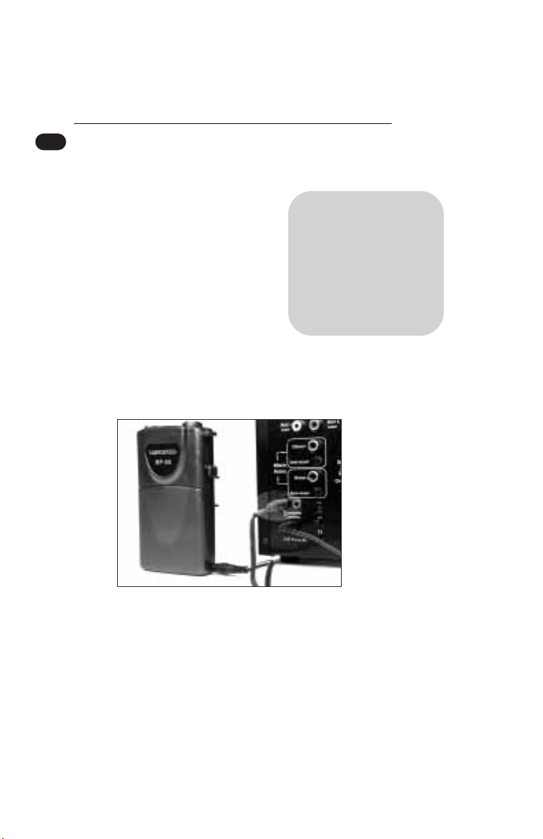
2 Your Belt-pack Transmitter has its
internal rechargeable batteries
already installed. Connect one end
of the Charging Cable to one of the
TRANSMITTER CHARGING jacks
on the back panel of the Receiver/
Amplifier. Connect the other end
of the Charging Cable to the
INPUT charging jack on the side of
the BP-60 Belt-pack Transmitter as
shown in the illustration.
Note The internal
rechargeable batteries are
not completely charged
when shipped. They must
be fully charged for 8 or
more hours before regular
classroom operation.
3 The battery charging indicator LED (labeled CHARGING)
lights green when the Transmitter is connected with a
charging cable to the TRANSMITTER CHARGING jack on
the back panel of the Receiver/Amplifier. When charging is
complete (8-12 hours), the CHARGING indicator light will
turn off.
Page 5

6 LES 600 OPERATING INSTRUCTIONS
4 NiMH batteries will usually maintain their charge for a full
day of normal classroom use. Always switch the Transmitter
OFF when not in use (lunch hour, quiet times, etc.).
Should the batteries in the Transmitter need to be changed,
open the lower plastic cover by pressing the ribbed
portions on both sides of the cover (located near the center
of the Transmitter) towards each other. At the same time,
pull forward on the cover, rotating it on the hinges located
at the bottom of the cover. Insert the new batteries (paying
attention to the + and - as indicated inside the case).
Rotate the cover back toward the Transmitter center and
snap it back into a locked position.
5 To attach the Microphone to the Transmitter, align the
microphone plug over the belt-pack connector jack. With
the black plastic dot facing forward, gently guide the connector into the jack. Be sure not to put undue stress on the
wire or connector. To remove the Microphone, simply press
inwards on the black plastic dot located on the microphone
connector. Holding the connector rather than pulling on the
wire, gently remove the connector from the Transmitter jack.
6 A switch on the top of the Transmitter case activates the
Transmitter. When turned ON, the red POWER indicator
will flash briefly.If the indicator remains lit continuously,
the battery charge is getting too low and must be recharged.
Note There is a delay
of about one-second from
the time the Transmitter
switch is turned ON until
the Receiver sends a signal
to the Amplifier. This is
normal.
When the Transmitter power is turned
OFF, the microphone audio to the
Receiver is automatically muted.
Page 6
LES 600 OPERATING INSTRUCTIONS 7
Step 3
Positioning Your Microphone
After the microphone is connected to the belt-pack Transmitter,
position the microphone as described below:
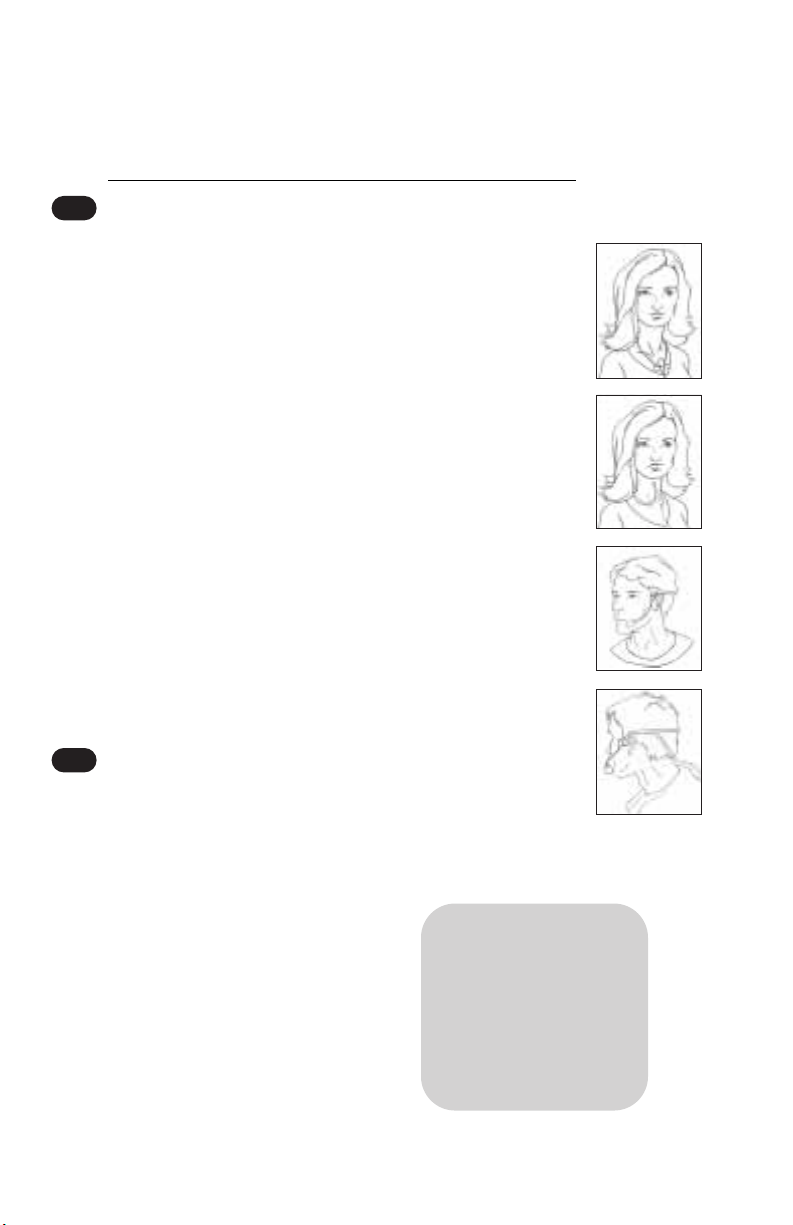
1 Lavaliere Microphone: The lavaliere microphone should be
hung around the neck as illustrated, resting on your collar
bone. The neck cord is adjusted by squeezing the two long
ends together and then sliding the adjuster up or down the cord.
2 Flexible Collar Microphone: The flexible collar microphone
is wrapped around the neck with the microphone element
positioned 3-4 inches from the mouth, as shown.
3 Noise-canceling Headset Microphone: The headset micro
phone is placed from behind the head over both ears. (Like
putting a pair of glasses on backwards). The microphone
arm is then adjusted up or down to follow along your jaw
line with the microphone element at the end positioned
about 3/4” from the chin as shown. The flat side (with
screwhead) should be facing away from your mouth.
Step 4
Adjusting Microphone Volume
1 Make sure the Receiver/ Amplifier is switched ON and the
Microphone is securely connected to the Transmitter.
2 Switch the Transmitter to the ON
position. The red POWER indicator
on the Transmitter will flash briefly.
The yellow RF INDICATOR on the
front panel of the Receiver/
Amplifier should light, indicating
that it is receiving the Transmitter
signal and is ready for use.
Note Feedback or
"squealing" may occur if
the volume is set too high.
Reducing the loudness of
the speakers with the
volume control usually
eliminates feedback.
Page 7
8 LES 600 OPERATING INSTRUCTIONS
3 When speaking at a normal voice level, the green AF INDI-
CATOR on the Receiver/Amplifier front panel should flash
on and off as the voice level goes up and down. While
speaking at a conversational voice level, slowly turn the
MIC 1 VOLUME control knob clockwise to increase the
loudness of the speakers until the sound level is adequate for
the room.
Step 5
Power for Your *Optional* Hand-held Microphone
The Hand-held Microphone comes with a Battery Charger and
three (3) NiMH rechargeable batteries.
1 Confirm that the Receiver/
Note The rechargeable
batteries are not fully
charged prior to delivery. In
order to prolong battery
life, batteries should be
charged for at least 8 hours
before first using.
Amplifier is connected to a
standard electrical wall outlet or
power strip.
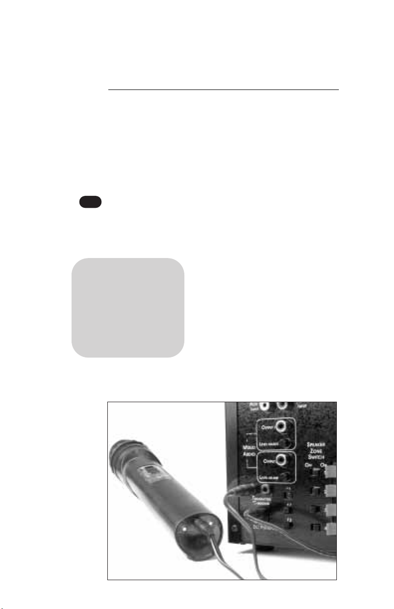
2 To charge the Hand-held
Microphone/Transmitter, connect
the Microphone/ Transmitter to the
Receiver/ Amplifier as shown using
a Charging Cable. The green CHARGING light on the front
of the Receiver/Amplifier will come on.
Page 8

LES 600 OPERATING INSTRUCTIONS 9
3 The batteries will fully charge in about 8-12 hours.
4 When in normal use, it is best to
leave batteries on the charger until
used, since there is a small amount
of discharge after 48 hours.
However, do not leave battery(ies)
plugged into the charger for more
than 5 days as it will significantly
shorten your battery life.
5 Once the batteries are charged,
remove the Charger Cable from
the Transmitter.
6 Make sure the Receiver/Amplifier is switched ON.
Note If the batteries are
not going to be used for an
extended period of time
(Christmas, spring, summer
break, etc.) it is important
to charge the battery for
at least 8 hours before
removing them from the
Charger and then storing
them (not in the Transmitter)
in a dry, mild temperature
environment.
7 Switch the Transmitter to the “ON”
position. A switch on the side of
the Transmitter case activates the
microphone. When turned ON,
the red battery condition indicator
will momentarily flash and a green
Note The Hand-held
Microphone will best
transmit a child’s voice
when held 1-2 inches
from the mouth.
light will glow, indicating that the
Transmitter battery is good. When
the red indicator remains lit continuously, the batteries are getting too low and should
be changed. There is a delay of about one-second from
the time the Transmitter switch is turned on, to when
the Receiver will send the signal to the Amplifier. This is
normal. The amber RF light on the front panel should
light, indicating that it is receiving the Transmitter signal
and is ready for use.
Page 9

10 LES 600 OPERATING INSTRUCTIONS
8 When speaking at a normal voice level, the green AF indi-
cator light (on the Receiver/Amplifier front panel) should
flash on and off as the voice level goes up and down. While
speaking at a normal voice level, slowly turn the MIC 1
VOLUME or MIC 2 VOLUME (if applicable) control on
the LES 600 clockwise to increase the loudness of the
speaker(s) until the sound level is adequate for the room.
Connecting to Other
Audio Equipment
CD or Cassette Player, VCR or TV
Note The AUX1 INPUT
and AUX2 INPUT jacks are
monaural. If a stereo source
like a CD, VCR or tape player is used, a common
stereo-to-mono adapter is
necessary to convert the
stereo signal to mono for
input to the LES 600.
audio source to the AUX 1 INPUT or
AUX 2 INPUT on the back of the
Receiver/Amplifier using an RCA-type
male connector.
With the Receiver/Amplifier turned
on, and the MIC 1 VOLUME or MIC
2 VOLUME switch turned on, slowly
increase the appropriate AUX 1
VOLUME or AUX 2 VOLUME on the front of the Receiver/
Amplifier. Increase the level until audio from the audio source
is heard through the speaker.
Assistive Listening Devices (ALD)
Select MIXED AUDIO OUTPUT 1 or OUTPUT 2 on the back
of the Receiver/Amplifier. Turn the selected Mixed Audio
Output LEVEL ADJUST fully counter-clockwise.
Connect the Mixed Audio Output of the Receiver/ Amplifier
with a cable having a RCA connector at one end. Connect the
other end of that cable to the ALD transmitter using a connector that will properly fit. Different manufacturers use different
audio input jacks to their Transmitters. For example, PhonicEar
Connect a line-level output from the
Page 10
LES 600 OPERATING INSTRUCTIONS 11
and Telex transmitters use 2.5mm and
3.5mm audio input jacks, respectively.
With the Receiver/Amplifier turned
ON, increase the Mixed Audio Output
LEVEL ADJUST slowly clockwise until
you reach a comfortable volume.
Note If you have any
questions regarding the
connection of assistive
listening devices contact
LightSPEED for technical
assistance at
1-800-732-8999.
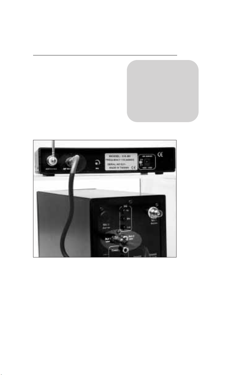
Connecting to A LightSPEED CX-50 Receiver
A 1/4” phone-to-RCA cable is used. The 1/4” phone plug goes
into the AF OUT jack on the back of the CX-50. The RCA plug
is inserted into AUXILIARY INPUT jack on the Receiver/
Amplifier. For the best sound quality, the volume adjustment
on the front of the CX-50 should be turned clockwise as far as
it will go. Depending on which AUX INPUT jack is selected,
the audio output is adjusted using AUX1 or AUX2 VOLUME
controls on the front of the Receiver/Amplifier.
Page 11

12 LES 600 OPERATING INSTRUCTIONS
Tips on Using Classroom
Amplification
These helpful suggestions are provided to maximize the
successful use of your new Classroom Amplification system:
• Involve your students in this new process right from the
beginning. When setting the volume, ask the students,
“What is the correct volume?” (Each level will seem
“louder” for them than you.) Ask, “When should we use
the hand-held microphone?” Some teachers introduce the
system by passing the hand-held microphone around the
room for each student to say hello.
• With the Lavaliere and Flexible Collar Microphone,
position the microphone so that it is 4-5 inches from your
mouth. This allows a good signal to be picked up yet is
far enough from the mouth to minimize extraneous noises
generated during speech. Keep the foam cover on the
microphone to help reduce additional noise.
• Speak in a natural voice. A normal conversational speech
level should provide an adequate speech signal. It is not
necessary to increase the intensity of your voice because
the FM system is providing adequate amplification
(approximately 5-10 dB) above your normal voice level.
• Avoid wearing jewelry that may rub or knock against the
microphone or mic cord and produce unwanted noise.
• Find a safe, secure place away from excessive heat, cold
or dampness for overnight storage of the Transmitter and
Hand-held Microphone. Do not wrap the cord around the
Transmitter.
• Use the on/off control on the Transmitter to mute the
system when needed (such as during private conversations
with a student, parent, or other classroom visitor). Since
this equipment is sometimes capable of transmitting more
than 100 feet, private conversations in the hallway, in the
staff room or on the playground may also be broadcast to
the class if the Transmitter is not turned off!
Page 12

LES 600 OPERATING INSTRUCTIONS 13
• Turn the body-pack Transmitter and/or the Hand-held
Microphone OFF whenever leaving the classroom.
• Recharge batteries each night. Operating time (actual usage) for
the Transmitter when using the rechargeable batteries should be
more than adequate for a typical school day. Your rechargeable
batteries should last for a normal school year if properly cared for.
• Do not recharge disposable batteries as they can overheat and
explode, creating a significant hazard. This may also damage
the Battery Charger or Transmitter, voiding the warranty.
• Try to avoid bumping or dropping the Microphone and/or
Transmitter. Treat cords (particularly near the attachments),
microphones, and batteries gently. These are usually the areas
that tend to malfunction first from misuse.
• Avoid winding the Microphone cable around the body-pack
Transmitter. This can damage or break the connecting cord,
producing static or noise in the FM system.
• Avoid blowing into the microphone when testing it. Instead, rub
fingers over the foam microphone cover, or snap fingers near the
microphone. Or conduct a consonant test by saying “ah, bah, s,
sh, th”, etc. These consonant sounds represent some of the softer
frequency ranges of speech and if they can be heard and distinguished, your equipment is working effectively.
• The Receiver/Amplifier has two auxiliary sound source input
jacks that may be used to amplify additional complimentary
audio from a VCR, CD-ROM, computer, cassette tape player,
etc., with a simple connecting cable (not included).
For any difficulty or questions not addressed here,
please contact LightSPEED’s Service Department at
1-800-732-8999, 7:00am - 5:00pm PST.
Page 13
14 LES 600 OPERATING INSTRUCTIONS
g
e
e
Mic2
e
Mic1
e
AF
AF
Power
Power
600
T e c h n o l o g i e s
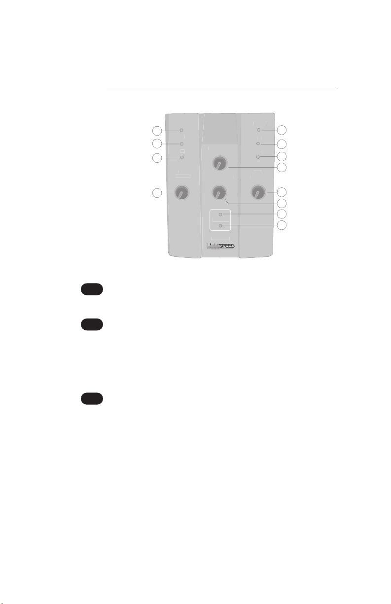
Reference Guide to Controls
5
6
7
8
9
10
11
12
1 & 5
Power Indicator:
1
2
3
Volum
4
Aux1 Volum
Aux2 Volum
Chargin
LES-
Volum
When power is switched on, the red POWER light will come on.
2 & 6
Radio Frequency Indicator:
The RF Indicator displays that the LES 600 is receiving a radio
signal from the instructor’s body-pack Transmitter (or Handheld Microphone). When the Transmitter is turned ON the
amber RF Indicator will light up.
3 & 7
Audio Frequency Indicator:
The AF Indicator displays that the voice of the instructor is
active and at an adequate level. When the Transmitter is turned
on, the green AF indicator will flash on and off as the instructor’s voice is detected.
Page 14
LES 600 OPERATING INSTRUCTIONS 15
4 & 9
Power and Volume Switch for Microphones:
Rotating the Mic 1 Volume control or Mic 2 Volume control
clockwise past the first “click” turns the LES 600 on.
Continuing to rotate this knob clockwise will increase the
volume of the wireless microphone through the speaker
system.
8 & 10
Aux1 and Aux2 Volume Control:
Rotating the Auxiliary Volume Control clockwise increases the
loudness of an audio source connected to the AUXILIARY
INPUT jack (located on the back panel).
11 &12
Battery Charging Indicator
These indicators light when a Transmitter is connected to one
of the TRANSMITTER CHARGING jacks (located on the back
of the Receiver/Amplifier, labeled 14 & 15 on the following
diagram). When charging is complete the indicator turns off.
Note The LES 600 comes standard with
a single wireless receiver that is controlled
using MIC1 VOLUME. If an optional second
wireless receiver is installed, the second receiver
is controlled using MIC2 VOLUME.
Page 15
16 LES 600 OPERATING INSTRUCTIONS
EQ
Mid
ow
putInput
Level Adjust
s
er
g
Mixed
Audio
u
Mic 1
Mic 2
1Aux 2
Output 2
22
21
20
19
18
17
16
15
14
13
13
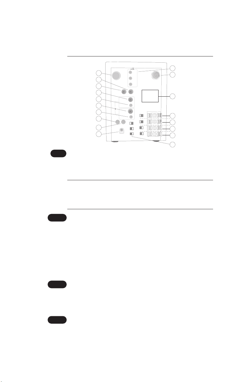
DC Power Connector:
Antenna
Aux
In
Tran
Chargin
DC Power In
Output 1
Level Adjust
mitt
Hi
Speaker
Zone
Switch
Antenna
Speaker
Ouputs
1
2
3
4
L
F2
F3
23
24
25
26
27
28
29
30
The Receiver/Amplifier requires a 15-volt, 2.4 Amp DC power
supply. The center conductor is positive (+) polarity.
Caution: Power supplies from different manufacturers have various
output voltages, current ratings, and polarity. Connecting the wrong
type of power supply can result in damage to the LES 600.
Transmitter Charging Jacks:
14 & 15
This is used to charge the rechargeable NiMH batteries in the
belt-pack Transmitter and optional Hand-held Microphone.
One end of the charging cable is connected to this jack. The
other end of the charging cable is connected to the BATTERY
CHARGING INPUT located on the side of the belt-pack
Transmitter, or bottom of the Hand-held Microphone.
See previous diagrams on page 5 and 8.
16 & 18
Mixed Audio Output Level Adjust:
Rotating the MIXED AUDIO OUTPUT ADJUST clockwise
increases the level of the audio signal at the Mixed Audio
Output jack located on the back panel.
17 & 19
Mixed Audio Output Jack:
The Mixed Audio Output jack sends to an external source, the
same audio information that is being supplied to the speaker
system. For example, this output could be used to connect to a tape
recorder for recording purposes, or to an assistive listening device
such as LightSPEED’s LES-360 FM Personal Listening System.
Page 16

LES 600 OPERATING INSTRUCTIONS 17
20 & 21
Aux1 and Aux2 Input Jacks:
The AUXILIARY INPUT jack is used to connect to an external
audio source (for example, a CD or tape player to add background music) to mix with your voice audio from the wireless
microphone. AUX1 level is adjusted by using the AUX1
VOLUME on the front; AUX2 is adjusted by AUX2 VOLUME.
22 & 24
Antenna Connector:
The chrome antenna is connected to the Antenna Connector on
back of the Receiver/Amplifier. The antenna should be kept
vertical for best reception. MIC2 ANTENNA is used if an
optional second wireless receiver is installed.
EQ Adjusters:
23
The three Frequency Equalization Adjustments are factory
set for a normal classroom environment. These EQ adjusters
function similar to the “bass” and “treble” on your home stereo.
A combination of small adjustments to these knobs will help
clarify your amplified voice tones for better student hearing and
comprehension. Adjustments to the high, medium, or low
frequencies can assist with the removal of “squeal” or feedback.
25
Serial Numbers and Frequency:
These labels inform you of your system’s serial numbers and
wireless frequency. You will need this information any time you
call LightSPEED’s Service Department.
26-29
Speaker Output Connectors:
These connectors are used to attach the wires from the loudspeaker system to the Receiver/Amplifier. Each connector pair
has its own switch to allow for speaker zones.
30
Speaker Filters:
These filters (labeled LF, MF and HF) are preset at the factory
for optimum performance. If you have questions or concerns
about these filters or their settings, please call LightSPEED or
see your speaker installation instructions.
Page 17

18 LES 600 OPERATING INSTRUCTIONS
Trouble Shooting Guide
Please go through this checklist before calling LightSPEED
Technologies Service Department.
Battery Check
• Transmitters are charged via a
Note Most problems
associated with wireless FM
systems are directly related
to low battery power. The
first thing to check is the
batteries.
• Be sure Transmitter is turned OFF while charging.
• The batteries used in the Hand-held microphone are also
charged from the Transmitter Charging jack on the back of
the Receiver/Amplifier.
jumper cable from the back of
the Amplifier. Make sure plugs
are secured, and in the proper
jacks.
• Confirm the CHARGING light
located on the front panel of the
amplifier is on while charging.
Hearing Static
• Test Transmitter with fully charged batteries. Regular alka-
line batteries may be used for testing purposes.
• Confirm the plug on the microphone cable is firmly seated
into the Transmitter jack.
• If you have access to another mic, try it in your Transmitter.
If it works, your original mic may need to be replaced.
If the system checks out okay, and you still hear some
occasional static or popping, you may be experiencing
radio frequency interference (RFI). If the mic is okay, and
you think it may be interference, confirm that your frequency is not being duplicated by another wireless FM
system within the building. Continued RFI may require
exchanging your system for one with a different frequency.
• Keep Receiver/Amplifier at least 6 ft. away from computers.
Page 18

LES 600 OPERATING INSTRUCTIONS 19
Low Volume
• Check volume level on Receiver and adjust as necessary.
• If volume is too low, check the “MT” adjustment inside the
battery compartment of the belt-pack Transmitter. Clockwise
adjustment of the “MT pot” will increase volume.
Sound Fades In and Out (Drop Out)
• Confirm Amplifier antenna is securely attached and visible from
all areas of the room where the Transmitter is operating.
• Test transmitter with fully charged batteries. You can use any
known, good quality batteries for testing.
No Sound From Speaker
• Confirm the Transmitter and Receiver have matching
frequencies. Check both MIC 1 VOLUME and MIC 2
VOLUME. If system is equipped with optional Mic 2 Receiver,
look for second antenna on back of Receiver/Amplifier.
• Confirm the plug on the microphone cable is securely fitted
into the Transmitter microphone jack.
• Confirm Amplifier power supply is the correct type, is
connected securely in the wall outlet and into the back of the
Receiver/Amplifier.
• Turn on Receiver/Amplifier; confirm that the POWER light
located on the front panel is on.
• Check volume.
• Turn on Transmitter and confirm amber RF light, located
on the front panel of the Receiver/Amplifier, flashes when
speaking into the microphone.
• Confirm batteries in the Transmitter are good. The red
battery indicator light should flash once as you turn on the
Transmitter. The same holds true with the hand-held microphone. If the red light stays on, your batteries are low.
Page 19

20 LES 600 OPERATING INSTRUCTIONS
• Check to confirm speaker wires are in the correct wire
terminals on the back of the Receiver/Amplifier and confirm
that the speaker switch for that speaker output is in the ON
position. Black (or black stripe) to black terminal. White or
gray wire to red terminal.
Transmitter Care
• Cleaning the microphone jack and battery contacts will
help ensure that your system gives you years of reliable
service. We recommend using “deoxidizer” or contact
cleaner every 2 or 3 months.
Battery Maintenance & Care
• Battery should fit snugly against the contact points inside
the battery compartment.
• Batteries are to be charged each night and over the
weekends. They should not be left charging over the
summer or during Christmas and Spring Breaks. Prior to
extended breaks, systems should be fully charged and
batteries removed from Transmitters. After extended breaks,
reinstall batteries and recharge batteries before using again.
• Battery removal in the Handheld Transmitter is achieved
by sliding down the battery cover and lifting the black
“ribbon” to pop the first battery out. Then pull the white
plastic battery guide towards the bottom of the Transmitter
while guiding the remaining two batteries out of the battery
compartment. Slide the white guide back into the Transmitter to install batteries.
If you have gone through this checklist and are still having
problems, write down the serial numbers and frequency of
your system. Call LightSPEED Service Department at
1-800-732-8999
7:00am – 5:00pm PST
Page 20

LES 600 OPERATING INSTRUCTIONS 21
FCC Notice
This device complies with part 15 of the FCC Rules.
Operation is subject to the following two conditions: (1) This
device may not cause harmful interference, and (2) this device
must accept any interference received, including interference
that may cause undesired operation.
Changes or modifications not expressly approved by the party
responsible for compliance could void the user’s authority to
operate this equipment.
This equipment has been tested and found to comply with the
limits of a Class B Digital Device, pursuant to Part 15 of the FCC
Rules. These limits are designed to provide reasonable protection against harmful interference in a residential installation.
This equipment generates, uses and can radiate radio frequency
energy and, if not installed and used in accordance with the
instruction may cause harmful interference to radio communication. However, there is no guarantee that interference will
not occur in a particular installation.
If this equipment does cause harmful interference to radio or
television reception, which can be determined by running the
equipment off and on, the user is encouraged to try to correct
the interference by one or more of the following measures:
• Reorient or relocate the receiving antenna.
• Increase the separation between the equipment and
receiver.
• Connect the equipment into an outlet on a circuit different
from that to which the receiver is connected.
• Consult LightSPEED for help (1-800-732-8999).
Page 21

22 LES 600 OPERATING INSTRUCTIONS
Warranty
Five Year Limited Warranty to Original Purchaser
LightSPEED 600-series Classroom Amplification Systems are
guaranteed against malfunction due to defects in materials and
workmanship for a period of five years, beginning at the date of
the purchase invoice. If such malfunction occurs, the product
will be repaired or replaced (at LightSPEED’s option) without
charge during the period and under the limitations stipulated
in the data sheet or this users manual. Limited exclusions
specifically apply to microphone elements, rechargeable
batteries, battery chargers and their assemblies, also external
cables and wires. Warranty on microphones/microphone
elements is limited to the original manufacturer’s warranty
(usually 1 year). If delivered prepaid to the LightSPEED
factory or an authorized warranty service center, the unit will
be returned prepaid. Warranty does not extend to finish,
appearance items, or malfunctions due to abuse or operation
other than specified conditions, nor does it extend to incidental
or consequential damages. Repair by other than LightSPEED
or its authorized service agencies will void this guarantee.
Information on authorized service agencies is available from
LightSPEED Technologies, Inc.
Extended warranties are available for most products. Please
contact LightSPEED for further information.
 Loading...