

Page 1

Page 2

Table of Contents
System Overview .......................................................................................................................................................1
System Controls and Functions:
Base Unit...............................................................................................................................................................2
Wireless Receivers ................................................................................................................................................ 4
Wireless T ransmitter Wireless T ransmitter -
CD Player.............................................................................................................................................................. 7
System Installation:
Power/Charging .................................................................................................................................................... 8
Speaker Stand -
Speaker/System Placement .................................................................................................................................10
Operating Instructions:
Base Unit.............................................................................................................................................................11
Wireless Microphones.........................................................................................................................................12
Wired Microphones............................................................................................................................................. 13
CD Player............................................................................................................................................................ 14
Active Link ..........................................................................................................................................................15
External Speakers................................................................................................................................................16
External Audio IN/OUT ........................................................................................................................................ 17
Wireless Receivers .............................................................................................................................................. 18
Installing or Replacing a Receiver Module.......................................................................................................19
Wireless T ransmitter Wireless T ransmitter -
CD-Player ...........................................................................................................................................................26
T rouble Shooting Guide...........................................................................................................................................28
Specifications:
Base Unit/T ransmitters ........................................................................................................................................ 29
Channel/Frequency Assignments............................................................................................................................. 30
Components & Accessories.....................................................................................................................................30
Warranty Information/Equipment Log.......................................................................................................................31
User Notes...............................................................................................................................................................32
handheld microphone ........................................................................................................
belt-pack............................................................................................................................
tripod ..........................................................................................................................................
handheld microphone ......................................................................................................
belt-pack..........................................................................................................................
20
23
5
6
9
TM
LightSPEED
LightSPEED is a trademark of LightSPEED Technologies, Inc. Other names and brands
may be claimed as the property of others. Copyright © 2005 LightSPEED Technologies, Inc.,
All rights reserved. Printed in USA.
Page 3
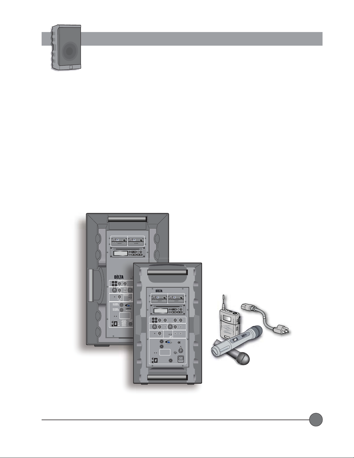
System Overview
The DEL TA X10 and X12 Wireless Sound Systems are powerful, rugged, and durable amplification systems designed for medium
to large-sized groups both indoors and out. The systems contain inputs for up to two UHF wireless microphone receivers,
optional integrated CD Player , two inputs for wired microphones, and an input for a line level audio source coming from a DVD
player , TV/VCR, Computer, etc. There is also a line output to connect to an external source such as a mixing console, an assistive
listening system or a recording device. Users can also connect to a passive speaker or a powered speaker in order to cover a
larger area. The systems operate on rechargeable battery power for up to 10 hours, and can also be plugged into AC power if
longer run-time is desired. An optional 12VDC cigarette lighter adaptor provides the ability to operate the systems using the
battery in your car in situations where there is no AC power available.
The wireless receivers contain 100 user-selectable frequencies ranging from 620 MHz to 745MHz. Each receiver contains a Clear
Channel Scan feature (a touch of a button automatically selects a clear frequency), low battery indicator (for the transmitter), and
adjustable squelch control. The systems are available with a variety of handheld, lapel, and headset microphones.
WIRELESS MIC 1 WIRELESS MIC 2
VOL
7100R
UHF TRUE
DIVERSITY
LightSPEED
RECEIVER
AB
CHANNEL
LOW
RF
SCAN SQ
BAT
NO
diSC
LINE
I
N
O
U
T
IN
MIC 1
MASTER
VOLUME
LIMIT
SWITCHED
8 OHM
8 OHM
ON MUTE
POWER
MaxPWR Min
7100R
UHF TRUE
DIVERSITY
LightSPEED
RECEIVER
AB
CHANNEL
LOW
RF
SCAN SQ
BAT
STOP PLAY/PAUSEA — BREPEAT
SCAN/SEARCH— SKIP —EJECT
Delta X12
VOL
MaxPWR Min
PROG
WIRELESS MIC 1 WIRELESS MIC 2
7100R
UHF TRUE
DIVERSITY
LightSPEED
RECEIVER
CHANNEL
LOW
BAT
NO
LINE/CD VOICE OVER MUSIC
LINE
I
N
O
U
T
min max dB dB
LEVEL
IN
MIC 1
min max
MASTER
VOLUME
LIMIT
min max
LEVEL
EXTERNAL
SPEAKER A
SWITCHED
8 OHM
EXTERNAL
SPEAKER B
8 OHM
ON MUTE
POWER
ON
OFF
MUTE
VOL
MaxPWR Min
AB
RF
SCAN SQ
CD-ROM ART GOES HERE
diSC
-40 0
LOW CUT
music speech
BATTERY
STATUS
LightSPEED
MADE IN EUROPE
DO NOT OPEN
THE COVER.
REFER SERVICING
TO QUALIFIED
PERSONNEL.
REPLACE FUSE
ONLY WITH
THE SAME TYPE
AND RATING.
Delta X10
Wireless
Sound System
VOL
7100R
UHF TRUE
DIVERSITY
LightSPEED
RECEIVER
MaxPWR Min
AB
CHANNEL
LOW
RF
SCAN SQ
BAT
PROG
STOP PLAY/PAUSEA — BREPEAT
SCAN/SEARCH— SKIP —EJECT
TONE CONTROLLEVEL
0
0
–+
–+
LOW
HIGH
LEVEL
IN
LOW CUT
music speech
min max
LOW CUT
LOW CUT
music speech
music speech
LOW OK
WIRELESS
WIRELESS
MIC 1
MIC 2
CHARGING STATUS
EXTERNAL
POWER
SOURCE
12VDC/4A
4
1
3
2
GND
+ 12V
MAINS
ACTIVE
AC
LINK
90-264V
47-63Hz
FUSE
T2A
MIC 2
ON
LightSPEED Technologies • Wireless Sound Solutions • Toll Free: 1-800-840-3662
1
Page 4

Controls and Functions
System Base Unit
WIRELESS MIC 1 WIRELESS MIC 2
VOL
7100R
UHF TRUE
DIVERSITY
LightSPEED
RECEIVER
AB
CHANNEL
LOW
RF
SCAN SQ
BAT
CD-ROM ART GOES HERE
NO
diSC
LINE
I
N
O
U
-40 0
T
min max dB dB
LEVEL
IN
LOW CUT
MIC 1
music speech
min max
MASTER
BATTERY
VOLUME
STATUS
LIMIT
min max
LEVEL
EXTERNAL
SPEAKER A
SWITCHED
8 OHM
EXTERNAL
SPEAKER B
8 OHM
ON MUTE
POWER
DO NOT OPEN
THE COVER.
REFER SERVICING
ON
TO QUALIFIED
PERSONNEL.
OFF
REPLACE FUSE
ONLY WITH
THE SAME TYPE
MUTE
AND RATING.
Delta X10
Wireless
Sound System
7100R
UHF TRUE
DIVERSITY
LightSPEED
RECEIVER
MaxPWR Min
AB
CHANNEL
LOW
RF
BAT
STOP PLAY/PAUSEA — BREPEAT
TONE CONTROLLEVELLINE/CD VOICE OVER MUSIC
0
–+
LOW
LEVEL
IN
min max
LOW CUT
music speech
LOW OK
WIRELESS
MIC 1
LightSPEED
MADE IN EUROPE
EXTERNAL
POWER
SOURCE
12VDC/4A
4
1
3
2
GND
+ 12V
MAINS
ACTIVE
AC
LINK
90-264V
47-63Hz
FUSE
T2A
SCAN SQ
SCAN/SEARCH— SKIP —EJECT
–+
LOW CUT
music speech
LOW CUT
music speech
WIRELESS
CHARGING STATUS
WIRELESS MIC 1 WIRELESS MIC 2
7100R
UHF TRUE
DIVERSITY
LightSPEED
RECEIVER
CHANNEL
AB
LOW
RF
SCAN SQ
BAT
1
VOL
MaxPWR Min
CHANNEL
LightSPEED
LOW
BAT
7100R
UHF TRUE
DIVERSITY
RECEIVER
AB
VOL
MaxPWR Min
RF
SCAN SQ
2
VOL
MaxPWR Min
PROG
0
HIGH
MIC 2
LINE
N
O
U
T
3
I
MIC 2
4
8 8
MIC 1
CD-ROM ART GOES HERE
NO
diSC
LINE/CD VOICE OVER MUSIC
-40 0
min max dB dB
5
LEVEL
IN
min max
LOW CUT
music speech
6
10 10
STOP PLAY/PAUSEA — BREPEAT
TONE CONTROLLEVEL
0
–+
LOW
LEVEL
IN
min max
PROG
SCAN/SEARCH— SKIP —EJECT
0
–+
HIGH
7
LOW CUT
music speech
MIC 2
9 9
SYSTEM CONTROLS and FUNCTIONSSYSTEM CONTROLS and FUNCTIONS
SYSTEM CONTROLS and FUNCTIONS
SYSTEM CONTROLS and FUNCTIONSSYSTEM CONTROLS and FUNCTIONS
1.1.
WIRELESS MIC 1/WIRELESS MIC 2:WIRELESS MIC 1/WIRELESS MIC 2:
1.
WIRELESS MIC 1/WIRELESS MIC 2:
1.1.
WIRELESS MIC 1/WIRELESS MIC 2:WIRELESS MIC 1/WIRELESS MIC 2:
These may be wireless receivers or blank filler panels depending on your system
configuration.
2.2.
CD PLACD PLA
2.
2.2.
3.3.
3.
3.3.
4.4.
4.
4.4.
YER:YER:
CD PLA
YER:
CD PLACD PLA
YER:YER:
LINE IN:LINE IN:
LINE IN:
LINE IN:LINE IN:
LINE OUTLINE OUT
LINE OUT
LINE OUTLINE OUT
This may be a CD player or a blank filler panel depending on your system configuration.
RCA input jacks from an external audio device such as a TV, DVD, Computer, or MP3 player.
: :
:
RCA output jacks to send a line level audio signal to an external device such as a mixing console, recording
: :
device, or assistive listening transmitter .
5.5.
LINE/CD LEVEL:LINE/CD LEVEL:
5.
LINE/CD LEVEL:
5.5.
LINE/CD LEVEL:LINE/CD LEVEL:
6.6.
VOICE OVER MUSIC:VOICE OVER MUSIC:
6.
VOICE OVER MUSIC:
6.6.
VOICE OVER MUSIC:VOICE OVER MUSIC:
Controls the level of the Line In jacks and the CD player .
Automatically lowers the volume of the audio from the Line In jacks and the CD player when any
sounds are produced at the microphone inputs. T urn the VOICE OVER MUSIC control down for less Line In/CD signal when
microphones are in use.
7.7.
TONE CONTROL:TONE CONTROL:
7.
TONE CONTROL:
7.7.
TONE CONTROL:TONE CONTROL:
These control the levels of the LOW and HIGH frequencies (bass and treble) for the CD player and Line
In jacks. These controls DO NOT affect the microphone inputs.
8.8.
MIC 1 IN/MIC 2 IN:MIC 1 IN/MIC 2 IN:
8.
MIC 1 IN/MIC 2 IN:
8.8.
MIC 1 IN/MIC 2 IN:MIC 1 IN/MIC 2 IN:
These XLR connectors provide balanced inputs with phantom power for wired microphones or
external wireless systems.
9.9.
MIC 1 LEVEL/MIC 2 LEVEL:MIC 1 LEVEL/MIC 2 LEVEL:
9.
MIC 1 LEVEL/MIC 2 LEVEL:
9.9.
MIC 1 LEVEL/MIC 2 LEVEL:MIC 1 LEVEL/MIC 2 LEVEL:
10.10.
MIC 1 LOW CUT/MIC 2 LOW CUTMIC 1 LOW CUT/MIC 2 LOW CUT
10.
MIC 1 LOW CUT/MIC 2 LOW CUT
10.10.
MIC 1 LOW CUT/MIC 2 LOW CUTMIC 1 LOW CUT/MIC 2 LOW CUT
These control the levels of the wired microphone inputs.
::
:
These controls allow users to cut out the low frequency sound of the wired micro
::
phones, making the speech more intelligible.
LightSPEED Technologies • Wireless Sound Solutions • Toll Free: 1-800-840-3662
2
Page 5
WIRELESS MIC 1 WIRELESS MIC 2
VOL
7100R
UHF TRUE
DIVERSITY
LightSPEED
RECEIVER
AB
CHANNEL
LOW
RF
SCAN SQ
BAT
CD-ROM ART GOES HERE
NO
diSC
LINE/CD VOICE OVER MUSIC
LINE
I
N
O
U
-40 0
T
min max dB dB
LEVEL
IN
LOW CUT
MIC 1
music speech
min max
MASTER
BATTERY
VOLUME
STATUS
LIMIT
min max
LEVEL
EXTERNAL
SPEAKER A
SWITCHED
8 OHM
EXTERNAL
SPEAKER B
8 OHM
ON MUTE
POWER
DO NOT OPEN
THE COVER.
REFER SERVICING
ON
TO QUALIFIED
PERSONNEL.
OFF
REPLACE FUSE
ONLY WITH
THE SAME TYPE
MUTE
AND RATING.
Delta X10
Wireless
Sound System
7100R
UHF TRUE
DIVERSITY
LightSPEED
RECEIVER
MaxPWR Min
AB
CHANNEL
LOW
RF
BAT
STOP PLAY/PAUSEA — BREPEAT
TONE CONTROLLEVEL
0
–+
LOW
LEVEL
IN
min max
LOW CUT
music speech
LOW OK
WIRELESS
MIC 1
LightSPEED
MADE IN EUROPE
EXTERNAL
POWER
SOURCE
12VDC/4A
4
1
3
2
GND
+ 12V
MAINS
ACTIVE
AC
LINK
90-264V
47-63Hz
FUSE
T2A
SCAN SQ
SCAN/SEARCH— SKIP —EJECT
–+
HIGH
LOW CUT
music speech
LOW CUT
music speech
WIRELESS
MIC 2
CHARGING STATUS
Controls and Functions
System Base Unit
... continued
12
11
MASTER
VOLUME
LIMIT
min max
LEVEL
VOL
MaxPWR Min
PROG
0
MIC 2
EXTERNAL
SPEAKER A
SWITCHED
8 OHM
EXTERNAL
SPEAKER B
8 OHM
ON MUTE
POWER
ON
OFF
MUTE
DO NOT OPEN
THE COVER.
REFER SERVICING
TO QUALIFIED
PERSONNEL.
REPLACE FUSE
ONLY WITH
THE SAME TYPE
AND RATING.
BATTERY
STATUS
LightSPEED
MADE IN EUROPE
13
LOW OK
ACTIVE
LINK
LOW CUT
music speech
WIRELESS
MIC 1
EXTERNAL
POWER
SOURCE
12VDC/ 4A
4
1
3
2
GND
+ 12V
MAINS
AC
90-264V
47-63Hz
FUSE
T2A
14
LOW CUT
music speech
WIRELESS
MIC 2
CHARGING STATUS
15
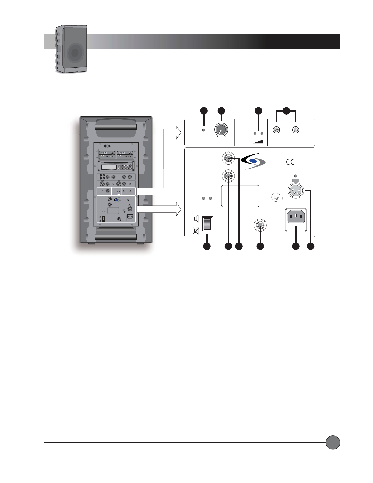
11.11.
LIMITLIMIT
11.
11.11.
12.12.
12.
12.12.
13.13.
13.
13.13.
14.14.
14.
14.14.
::
LIMIT
:
This LED lights up when the limiter is active, meaning that the power amplifiers are at maximum output.
LIMITLIMIT
::
MASTER VOLUME: MASTER VOLUME:
MASTER VOLUME:
MASTER VOLUME: MASTER VOLUME:
BABA
TTERTTER
Y STY ST
BA
TTER
Y ST
BABA
TTERTTER
Y STY ST
LOW CUT WIRELESS MIC 1/LOW CUT WIRELESS MIC 2:LOW CUT WIRELESS MIC 1/LOW CUT WIRELESS MIC 2:
LOW CUT WIRELESS MIC 1/LOW CUT WIRELESS MIC 2:
LOW CUT WIRELESS MIC 1/LOW CUT WIRELESS MIC 2:LOW CUT WIRELESS MIC 1/LOW CUT WIRELESS MIC 2:
Controls the overall volume level of the sound reaching the speaker(s).
AA
TUS:TUS:
A
TUS:
Indicates charge level of the internal batteries.
AA
TUS:TUS:
These controls allow users to cut out the low frequency
sound of the wireless microphones, making the speech more intelligible.
15.15.
POWER:POWER:
15.
15.15.
POWER:
POWER:POWER:
This switch turns the system ON and OFF. MUTE turns the system on while muting the internal and/or external
speaker(s).
16.16.
EXTERNAL SPEAKER B:EXTERNAL SPEAKER B:
16.
EXTERNAL SPEAKER B:
16.16.
EXTERNAL SPEAKER B:EXTERNAL SPEAKER B:
This ¼” phone connector provides a powered output for an external passive speaker
full sound to both the DEL TA X internal speaker and the external speaker).
17.17.
EXTERNAL SPEAKER A SWITCHED:EXTERNAL SPEAKER A SWITCHED:
17.
EXTERNAL SPEAKER A SWITCHED:
17.17.
EXTERNAL SPEAKER A SWITCHED:EXTERNAL SPEAKER A SWITCHED:
This ¼” phone connector provides a powered output for an external passive speaker
(mutes the DEL TA X internal speaker and provides full sound to the external speaker).
18.18.
ACTIVE LINK:ACTIVE LINK:
18.
ACTIVE LINK:
18.18.
ACTIVE LINK:ACTIVE LINK:
This balanced ¼” phone connector provides an audio link to another Delta X10 or Delta X12 system. When
connected properly, the sound from both Delta X systems is ‘shared’ between them.
the available inputs and sound level.
19.19.
MAINS:MAINS:
19.
MAINS:
19.19.
20.20.
20.
20.20.
This IEC connector is used for operating the system and charging the internal batteries from an AC source.
MAINS:MAINS:
EXTERNAL POWER SOURCE:EXTERNAL POWER SOURCE:
EXTERNAL POWER SOURCE:
EXTERNAL POWER SOURCE:EXTERNAL POWER SOURCE:
Provides a secondary power input for operation from 12VDC when the batteries are
discharged.
16 17
19
18
20
(provides
Using ACTIVE LINK, you can double
LightSPEED Technologies • Wireless Sound Solutions • Toll Free: 1-800-840-3662
3
Page 6

CHANNEL
VOL
7100R
UHF TRUE
DIVERSITY
LightSPEED
RECEIVER
LOW
BAT
AB
RF
SCAN SQ
MaxPWR Min
Controls and Functions
Wireless Receiver(s)
Delta X10
WIRELESS MIC 1 WIRELESS MIC 2
7100R
UHF TRUE
DIVERSITY
LightSPEED
RECEIVER
AB
CHANNEL
LOW
RF
SCAN SQ
BAT
CD-ROM ART GOES HERE
NO
diSC
LINE/CD VOICE OVER MUSIC
LINE
I
N
O
U
-40 0
T
min max dB dB
LEVEL
IN
MIC 1
min max
MASTER
VOLUME
LIMIT
min max
LEVEL
EXTERNAL
SPEAKER A
SWITCHED
8 OHM
EXTERNAL
SPEAKER B
8 OHM
ON MUTE
POWER
DO NOT OPEN
THE COVER.
REFER SERVICING
ON
TO QUALIFIED
PERSONNEL.
OFF
REPLACE FUSE
ONLY WITH
THE SAME TYPE
MUTE
AND RATING.
7100R WIRELESS RECEIVER CONTROLS and FUNCTIONS7100R WIRELESS RECEIVER CONTROLS and FUNCTIONS
7100R WIRELESS RECEIVER CONTROLS and FUNCTIONS
7100R WIRELESS RECEIVER CONTROLS and FUNCTIONS7100R WIRELESS RECEIVER CONTROLS and FUNCTIONS
1.1.
Wireless Receiver Power/VWireless Receiver Power/V
1.
Wireless Receiver Power/V
1.1.
Wireless Receiver Power/VWireless Receiver Power/V
olume Adjustment:olume Adjustment:
olume Adjustment:
olume Adjustment:olume Adjustment:
music speech
VOL
LOW CUT
BATTERY
STATUS
MaxPWR Min
LightSPEED
MADE IN EUROPE
VOL
7100R
UHF TRUE
DIVERSITY
LightSPEED
RECEIVER
MaxPWR Min
AB
CHANNEL
LOW
RF
SCAN SQ
BAT
PROG
STOP PLAY/PAUSEA — BREPEAT
SCAN/SEARCH— SKIP —EJECT
TONE CONTROLLEVEL
0
0
–+
–+
LOW
HIGH
LEVEL
IN
LOW CUT
MIC 2
music speech
min max
LOW CUT
LOW CUT
music speech
music speech
LOW OK
WIRELESS
WIRELESS
MIC 1
MIC 2
CHARGING STATUS
EXTERNAL
POWER
SOURCE
12VDC/4A
4
1
3
2
GND
+ 12V
MAINS
ACTIVE
AC
LINK
90-264V
47-63Hz
FUSE
T2A
Turn this knob clockwise to power up the receiver. Rotate to adjust the
Wireless
Sound System
audio output level.
100-channel UHF Receiver Module
7100R
UHF TRUE
DIVERSITY
LightSPEED
RECEIVER
CHANNEL
2
LOW
BAT
3
AB
RF
4
SCAN SQ
6
5
1
VOL
MaxPWR Min
7
2.2.
Channel Control:Channel Control:
2.
Channel Control:
2.2.
Channel Control:Channel Control:
3.3.
TT
ransmitter Low Batterransmitter Low Batter
3.
T
ransmitter Low Batter
3.3.
TT
ransmitter Low Batterransmitter Low Batter
Manually select the desired channel (00-99) by pressing these two buttons.
y Indicator:y Indicator:
y Indicator:
y Indicator:y Indicator:
This LED lights to indicate a low battery level in the transmitter
that is set to the same channel.
4.4.
RF Channel "A" Indicator:RF Channel "A" Indicator:
4.
RF Channel "A" Indicator:
4.4.
RF Channel "A" Indicator:RF Channel "A" Indicator:
5.5.
RF Channel "B" Indicator:RF Channel "B" Indicator:
5.
RF Channel "B" Indicator:
5.5.
RF Channel "B" Indicator:RF Channel "B" Indicator:
6.6.
Scan Button:Scan Button:
6.
Scan Button:
6.6.
Scan Button:Scan Button:
7.7.
Squelch Adjustment:Squelch Adjustment:
7.
Squelch Adjustment:
7.7.
Squelch Adjustment:Squelch Adjustment:
Press this button to automatically select a channel that is free from interference.
LightSPEED Technologies • Wireless Sound Solutions • Toll Free: 1-800-840-3662
The "A" LED lights up indicating the "A" channel tuner is receiving the strongest RF signal.
The "B" LED lights up indicating the "B" channel tuner is receiving the strongest RF signal.
Adjusts the squelch level for elimination of RF interference.
(handheld or belt-pack)
4
Page 7
N
O
Controls and Functions
Wireless Transmitter
Handheld Microphone
LOCK
4
1
DOWN
2
ON
3
CH: 002
LCD Display
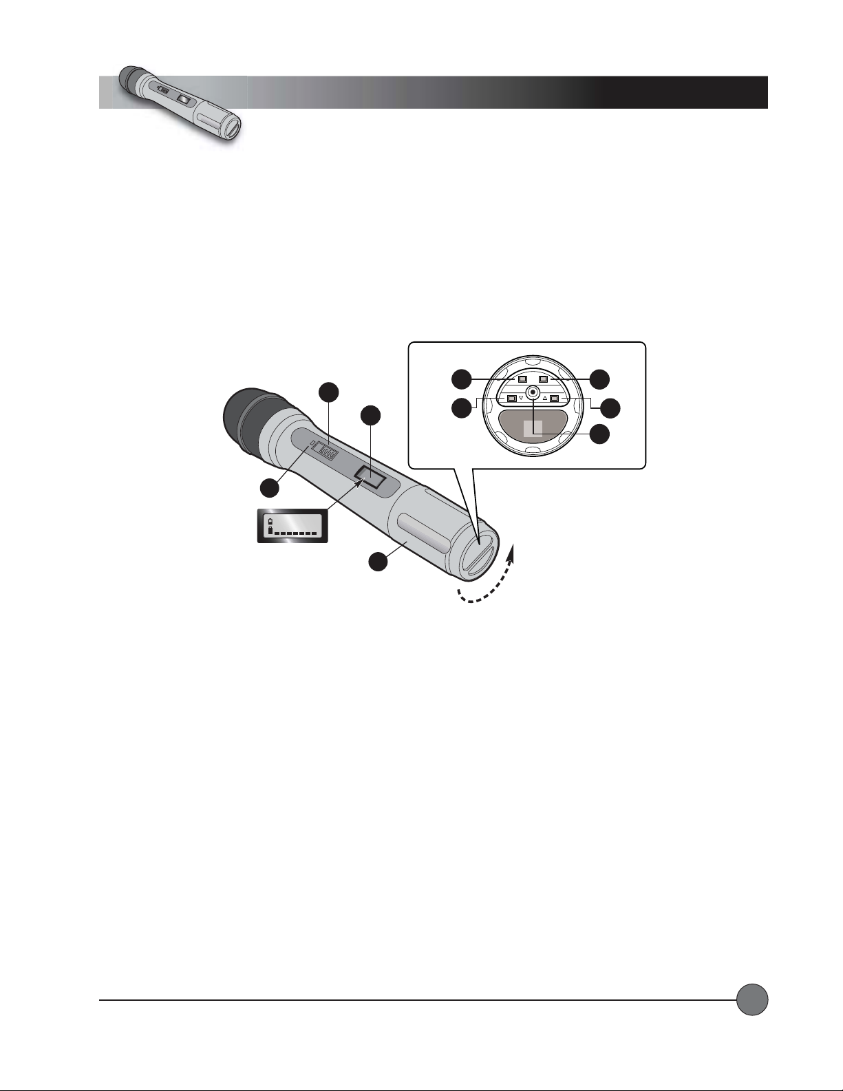
HM-900 HANDHELD MICROPHONE CONTROLS and FUNCTIONSHM-900 HANDHELD MICROPHONE CONTROLS and FUNCTIONS
HM-900 HANDHELD MICROPHONE CONTROLS and FUNCTIONS
HM-900 HANDHELD MICROPHONE CONTROLS and FUNCTIONSHM-900 HANDHELD MICROPHONE CONTROLS and FUNCTIONS
1.1.
Power Switch:Power Switch:
1.
Power Switch:
1.1.
Power Switch:Power Switch:
2.2.
LCD Display:LCD Display:
2.
LCD Display:
2.2.
LCD Display:LCD Display:
3.3.
Red LED:Red LED:
3.
Red LED:
3.3.
Red LED:Red LED:
Turns the transmitter ON.
Information screen appears when the power is switched on.
Lights up briefly when power is switched on.
8
Battery
Compartment
6
End View of Microphone
LOCK SET
HM-900
SET
5
UP
6
7
4.4.
Lock Button:Lock Button:
4.
Lock Button:
4.4.
Lock Button:Lock Button:
5.5.
Set Button:Set Button:
5.
Set Button:
5.5.
Set Button:Set Button:
6.6.
Up and Down Buttons:Up and Down Buttons:
6.
Up and Down Buttons:
6.6.
Up and Down Buttons:Up and Down Buttons:
Locks all microphone controls.
This button is used to enter and save changes to the transmitter settings.
These buttons scroll up and down between setup screens on the LCD display. They are also used
to enter changes in each setup screen.
7.7.
BatterBatter
7.
7.7.
8.8.
8.
8.8.
LightSPEED Technologies • Wireless Sound Solutions • Toll Free: 1-800-840-3662
y Charge Jack:y Charge Jack:
Batter
y Charge Jack:
BatterBatter
y Charge Jack:y Charge Jack:
BatterBatter
y Compartment:y Compartment:
Batter
y Compartment:
BatterBatter
y Compartment:y Compartment:
Optional battery charger plugs in here
Bottom section of microphone barrel unscrews to reveal batterycompartment.
(for NiMH batteries only).
5
Page 8
Controls and Functions
LightSPEED
1
On/Off
Switch
Display
2
LCD
CH: 001
LightSPEED
Red LED
Mute
Switch
3
Mic
Jack
Wireless Transmitter
Belt-pack
4
5
6
Battery
Charge
Jack
7
Belt
Clip
8
Gain
Adjust
Battery
12
Compartment
9
UP
10
Door
Latch
9
Set
11
GT
MT
DOWN
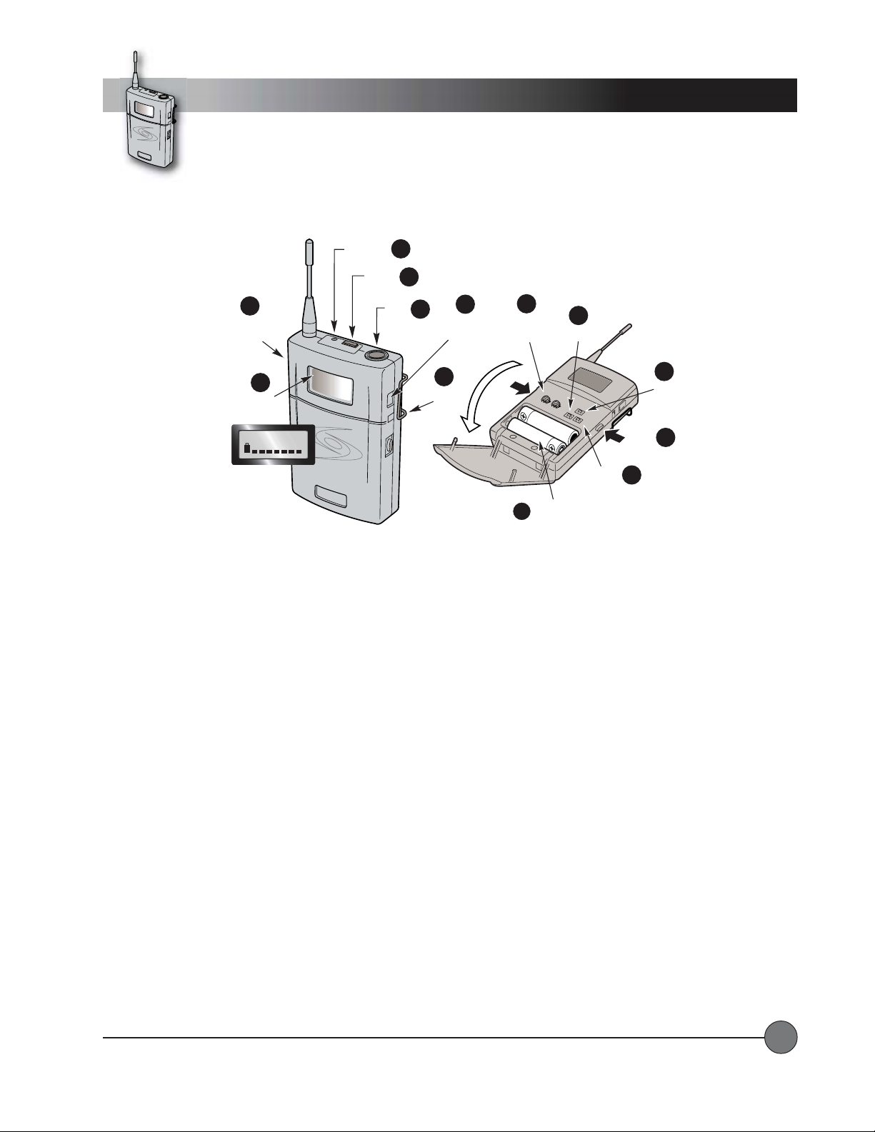
BP-900 BELBP-900 BEL
BP-900 BEL
BP-900 BELBP-900 BEL
1.1.
Power Button:Power Button:
1.
Power Button:
1.1.
Power Button:Power Button:
2.2.
LCD Display:LCD Display:
2.
LCD Display:
2.2.
LCD Display:LCD Display:
3.3.
Red LED:Red LED:
3.
Red LED:
3.3.
Red LED:Red LED:
4.4.
Mute Switch:Mute Switch:
4.
Mute Switch:
4.4.
Mute Switch:Mute Switch:
5.5.
Microphone Jack:Microphone Jack:
5.
Microphone Jack:
5.5.
Microphone Jack:Microphone Jack:
6.6.
BatterBatter
6.
Batter
6.6.
BatterBatter
7.7.
Belt ClipBelt Clip
7.
Belt Clip
7.7.
Belt ClipBelt Clip
8.8.
Gain:Gain:
8.
Gain:
8.8.
Gain:Gain:
9.9.
UP and Down Buttons:UP and Down Buttons:
9.
UP and Down Buttons:
9.9.
UP and Down Buttons:UP and Down Buttons:
to enter changes in each setup screen.
10.10.
Set Button:Set Button:
10.
Set Button:
10.10.
Set Button:Set Button:
11.11.
Door Latch:Door Latch:
11.
Door Latch:
11.11.
Door Latch:Door Latch:
12.12.
BatterBatter
12.
Batter
12.12.
BatterBatter
TT
-P-P
ACK TRANSMITTER CONTROLS and FUNCTIONSACK TRANSMITTER CONTROLS and FUNCTIONS
T
-P
ACK TRANSMITTER CONTROLS and FUNCTIONS
TT
-P-P
ACK TRANSMITTER CONTROLS and FUNCTIONSACK TRANSMITTER CONTROLS and FUNCTIONS
T urns the transmitter ON.
Information screen appears when the power is switched on.
Lights up briefly when power is switched on, flashes continuously when audio signal is muted.
Turns the audio signal on or off.
Microphone connects to transmitter here.
y Charge Jack: y Charge Jack:
y Charge Jack:
y Charge Jack: y Charge Jack:
Provides adjustment for differing voice levels and microphone sensitivities.
This button is used to enter and save changes to the transmitter settings.
A door latch button is located on each side. Press both to open the battery compartment door.
y Compartmenty Compartment
y Compartment
y Compartmenty Compartment
Optional battery charger plugs in here
These buttons scroll up and down between setup screens on the LCD display. They are also used
(Hold for two seconds.)
The red LED will flash when MUTE is engaged.
(for NiMH batteries only).
LightSPEED Technologies • Wireless Sound Solutions • Toll Free: 1-800-840-3662
6
Page 9

Controls and Functions
CD Player
CD PLACD PLA
CD PLA
CD PLACD PLA
1.1.
CD Slot:CD Slot:
1.
CD Slot:
1.1.
CD Slot:CD Slot:
2.2.
REPEAREPEA
2.
REPEA
2.2.
REPEAREPEA
3.3.
AA
3.
A
3.3.
AA
4.4.
STOP Button:STOP Button:
4.
STOP Button:
4.4.
STOP Button:STOP Button:
1
NO diSC
CD Player Front Panel
7
YER CONTROLS and FUNCTIONSYER CONTROLS and FUNCTIONS
YER CONTROLS and FUNCTIONS
YER CONTROLS and FUNCTIONSYER CONTROLS and FUNCTIONS
Insert CD here.
T Button:T Button:
T Button:
T Button:T Button:
--
B Button:B Button:
-
B Button:
--
B Button:B Button:
Press once to repeat a track, press twice to repeat an entire disc or playlist.
Sets start and end points for a playback loop.
Stops playback.
2
3
4 5
STOP PLAY/PAUSEA — BREPEAT
8
9
6
PROG
SCAN/SEARCH— SKIP —EJECT
10
5.5.
PLAPLA
Y/PY/P
5.
5.5.
6.6.
6.
6.6.
7.7.
7.
7.7.
8.8.
8.
8.8.
9.9.
9.
9.9.
10.10.
10.
10.10.
LightSPEED Technologies • Wireless Sound Solutions • Toll Free: 1-800-840-3662
AUSE Button:AUSE Button:
PLA
Y/P
AUSE Button:
PLAPLA
Y/PY/P
AUSE Button:AUSE Button:
PROG Button:PROG Button:
PROG Button:
PROG Button:PROG Button:
LCD Display:LCD Display:
LCD Display:
LCD Display:LCD Display:
EJECT Button:EJECT Button:
EJECT Button:
EJECT Button:EJECT Button:
SKIP Buttons:SKIP Buttons:
SKIP Buttons:
SKIP Buttons:SKIP Buttons:
SCAN/SEARCH Buttons:SCAN/SEARCH Buttons:
SCAN/SEARCH Buttons:
SCAN/SEARCH Buttons:SCAN/SEARCH Buttons:
playing ‘snippets’ to allow searching.
Starts playback or pauses playback.
Used to create playlists.
Shows information about the disc and current mode of operation.
Ejects the disc.
Skips to the beginning of the next or previous track.
Similar to fast forward and rewind. Moves quickly forward or backward through the disc while
7
Page 10
System Installation
2
Power/Charging
MASTER
VOLUME
LIMIT
min max
LEVEL
EXTERNAL
SPEAKER A
SWITCHED
8 OHM
EXTERNAL
SPEAKER B
8 OHM
ON MUTE
POWER
ON
OFF
MUTE
3
CHARGING THE BACHARGING THE BA
CHARGING THE BA
CHARGING THE BACHARGING THE BA
TTERTTER
TTER
TTERTTER
YY
Y
YY
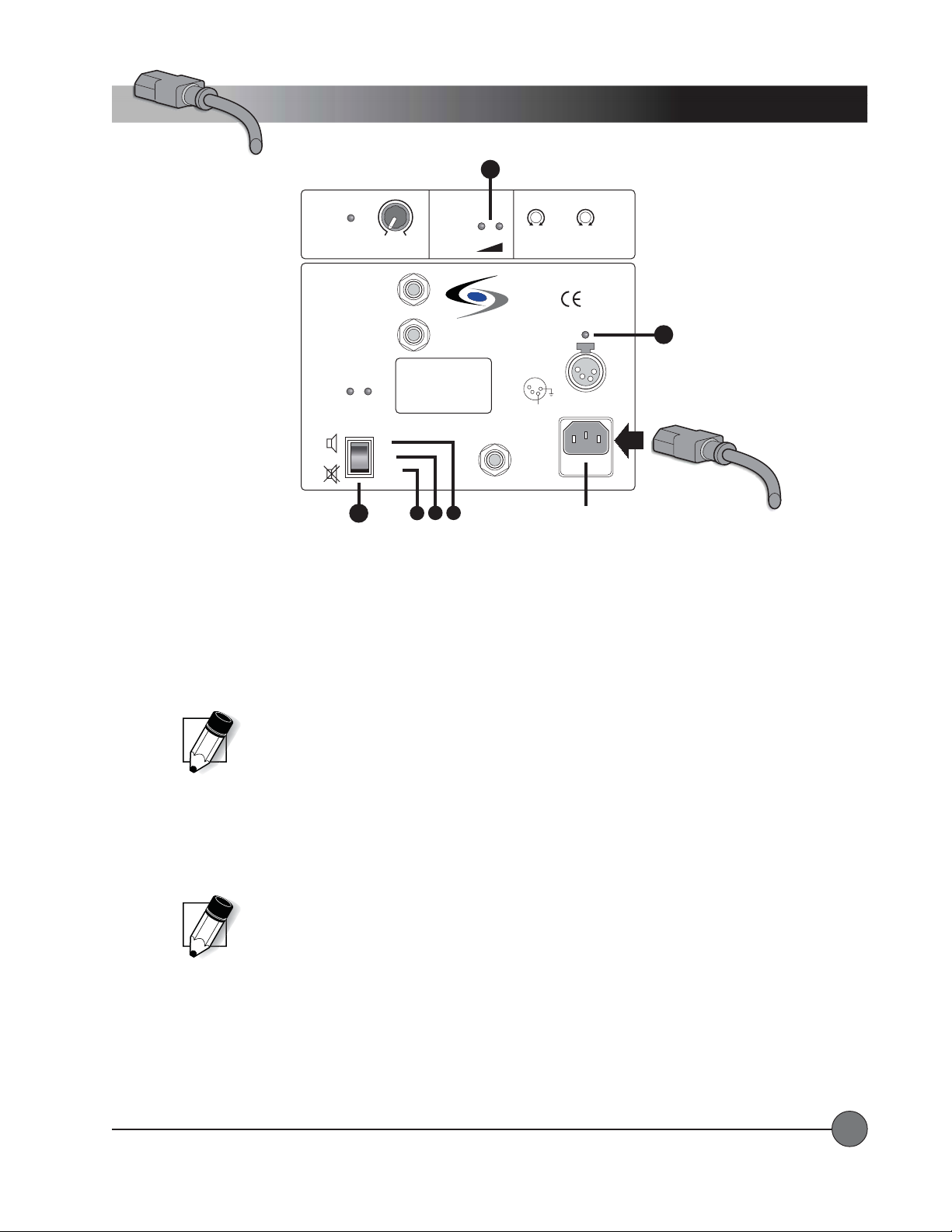
After unpacking the unit for the first time, please charge the batteries for at least 10 hours before operation. The battery charger
is built in as an integral part of the system. T o charge the batteries, plug one end of the IEC power cable into the MAINS
connector and plug the other end into an AC outlet (90-264VAC, 47-63Hz).
1. CHARGING STATUS LED: The Charging Status LED will light up when external power is supplied. The color of the LED
indicates the charging status as follows:
REDRED
•
RED means fast-charge mode.
REDRED
ORANGEORANGE
•
ORANGE means trickle-charge mode.
ORANGEORANGE
GREENGREEN
•
GREEN means no charging.
GREENGREEN
The batteries are very low or completely discharged.
The batteries are fully charged.
BATTERY
STATUS
DO NOT OPEN
THE COVER.
REFER SERVICING
TO QUALIFIED
PERSONNEL.
REPLACE FUSE
ONLY WITH
THE SAME TYPE
AND RATING.
B
C
LOW OK
LightSPEED
MADE IN EUROPE
A
ACTIVE
LINK
LOW CUT
music speech
WIRELESS
MIC 1
EXTERNAL
POWER
SOURCE
12VDC/ 4A
4
1
3
2
GND
+ 12V
MAINS
AC
90-264V
47-63Hz
FUSE
T2A
LOW CUT
music speech
WIRELESS
MIC 2
CHARGING STATUS
AC Power IN
The batteries are not yet fully charged.
1
IEC Power
Cable
NOTE: If the batteries are low and there is an AC outlet available, you can connect the AC
mains and operate the system as normal while the batteries are charging. However , to fully
charge the system, it should be switched OFF until the CHARGING STATUS LED turns green.
DETERMINING BADETERMINING BA
DETERMINING BA
DETERMINING BADETERMINING BA
TTERTTER
TTER
TTERTTER
Y STY ST
Y ST
Y STY ST
AA
A
AA
TUSTUS
TUS
TUSTUS
2. BA TTER Y STATUS LEDs: The Battery Status LEDs indicate the amount of charge available even when the AC mains are
disconnected. Whenever the batteries have enough charge to operate the system, the green OK LED will light. As the
batteries discharge, the red LOW LED will begin to glow, and the green OK LED will stay lit. When the red LOW LED is
glowing brightly, the battery is very low. Once the batteries discharge to an unusable level, the system will shut off and you
will need to connect to an external power source.
NOTE: It is possible to operate the system from a 12VDC external source when the batteries
are fully discharged and no AC power source is available. A special adaptor cable allows
connection directly to a car cigarette lighter . Contact LightSPEED for more information.
SYSTEM POWERSYSTEM POWER
SYSTEM POWER
SYSTEM POWERSYSTEM POWER
3. The POWER switch has three positions as follows:
A.A.
ONON
A.
ON Position: The green ON LED will light and the power amps will be active. This is the normal mode of operation
A.A.
ONON
with the internal and external speakers producing sound.
B.B.
OFFOFF
B.
OFF Position: No LEDs will light and the system is off.
B.B.
OFFOFF
C.C.
MUTEMUTE
C.
MUTE Position: The green ON LED and the amber MUTE LED will light and the power amps will be disabled. This is
C.C.
MUTEMUTE
a special mode of operation in which all of the controls and functions work as normal, but no sound is produced by
the internal or external speakers.
LightSPEED Technologies • Wireless Sound Solutions • Toll Free: 1-800-840-3662
8
Page 11
System Installation
Speaker Stand(tripod)
1
Locking
Knob
SPEAKER STSPEAKER ST
SPEAKER ST
SPEAKER STSPEAKER ST
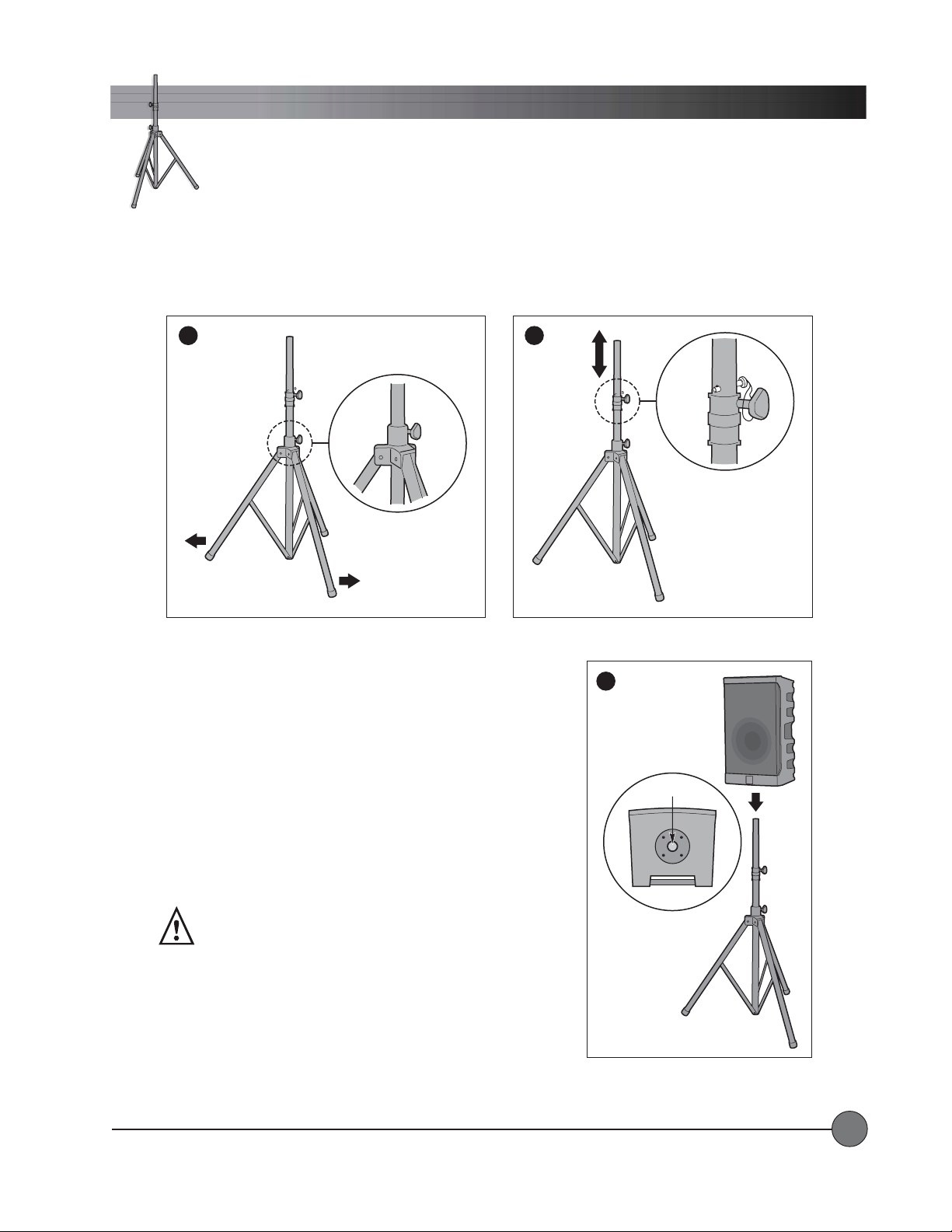
1.1.
Extending the Legs: Extending the Legs:
1.
Extending the Legs: Loosen the lower knob and pull outward on two
1.1.
Extending the Legs: Extending the Legs:
legs of the tripod. Extend the legs until the center post is just above the
floor . The center post should NOT touch the floor.
AND (TRIPOD)AND (TRIPOD)
AND (TRIPOD)
AND (TRIPOD)AND (TRIPOD)
Tighten the lower
knob.
2
Safety
Pin
Locking
Knob
3
2.2.
Extending the Center Post:Extending the Center Post:
2.
Extending the Center Post: Loosen the upper knob and pull the center
2.2.
Extending the Center Post:Extending the Center Post:
post up to the desired height. There are eight thru-holes in the center
post. Locate the thru-hole nearest to the collar and insert the safety
pin in that hole. Lower the center post until the safety pin sits on the
collar .
Tighten the upper knob.
3.3.
Mounting the Delta X:Mounting the Delta X:
3.
Mounting the Delta X:
3.3.
Mounting the Delta X:Mounting the Delta X:
WARNING: Safe handling of this
system requires two people.
For safety, two people are required to mount the Delta X system on the
tripod. Lift the Delta X system above the top of the center post. Align
the mounting hole with the center post of the tripod and carefully lower
the Delta X system onto it.
LightSPEED Technologies • Wireless Sound Solutions • Toll Free: 1-800-840-3662
Tripod Mount
Bottom View of
Delta X10
9
Page 12
System Installation
yp
Speaker/System Placement
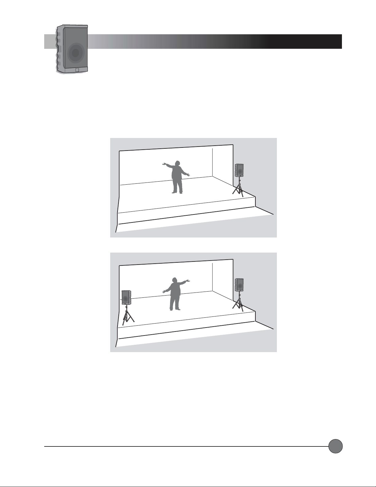
T ypical stage placement f or ONE Delta X system.
T
ical stage placement for TWO Delta X systems.
SPEAKER PLACEMENTSPEAKER PLACEMENT
SPEAKER PLACEMENT
SPEAKER PLACEMENTSPEAKER PLACEMENT
The Delta X system(s) should be placed in a location that is slightly in front of the area in which microphones will be used,
typically at the front edge of a stage.
(SEE ILLUSTRATIONS)
LightSPEED Technologies • Wireless Sound Solutions • Toll Free: 1-800-840-3662
10
Page 13
Operating Instructions
C
C
n
max
LEVEL
music
min
LEVEL
LOW CUT
c
sp
h
System Base Unit
WIRELESS MIC 1 WIRELESS MIC 2
VOL
7100R
UHF TRUE
DIVERSITY
LightSPEED
RECEIVER
AB
CHANNEL
LOW
RF
SCAN SQ
BAT
CD-ROM ART GOES HERE
NO
diSC
LINE/CD VOICE OVER MUSIC
LINE
I
N
O
U
-40 0
T
min max dB dB
LEVEL
IN
LOW CUT
MIC 1
music speech
min max
MASTER
BATTERY
VOLUME
STATUS
LIMIT
min max
LEVEL
EXTERNAL
SPEAKER A
SWITCHED
8 OHM
EXTERNAL
SPEAKER B
8 OHM
ON MUTE
POWER
DO NOT OPEN
THE COVER.
REFER SERVICING
ON
TO QUALIFIED
PERSONNEL.
OFF
REPLACE FUSE
ONLY WITH
THE SAME TYPE
MUTE
AND RATING.
Delta X10
Wireless
Sound System
7100R
UHF TRUE
DIVERSITY
LightSPEED
RECEIVER
MaxPWR Min
AB
CHANNEL
LOW
RF
BAT
STOP PLAY/PAUSEA — BREPEAT
TONE CONTROLLEVEL
0
–+
LOW
LEVEL
IN
min max
LOW CUT
music speech
LOW OK
WIRELESS
MIC 1
LightSPEED
MADE IN EUROPE
EXTERNAL
POWER
SOURCE
12VDC/4A
4
1
3
2
GND
+ 12V
MAINS
ACTIVE
AC
LINK
90-264V
47-63Hz
FUSE
T2A
SCAN SQ
PROG
SCAN/SEARCH— SKIP —EJECT
0
–+
HIGH
LOW CUT
music speech
LOW CUT
music speech
WIRELESS
MIC 2
CHARGING STATUS
VOICE OVER MUSIC
3
-40 0
dB dB
VOL
MaxPWR Min
MIC 2
LINE
I
N
O
U
T
1
I
MASTER
VOLUME
LINE/CD VOICE OVER MUSIC
min max dB dB
mi
LIMIT
min max
LEVEL
-40 0
LOW CUT
speech
BATTERY
STATUS
4
TONE CONTROL
0
–+
LOW
–+
LOW CUT
music speech
LOW OK
WIRELESS
–+
TONE CONTROLLEVEL
0
LOW
MIC 1
–+
musi
max
LOW CUT
music speech
WIRELESS
0
HIGH
MIC 2
HIGH
eec
0
2
I
1
2
LIMIT
min max
LEVEL
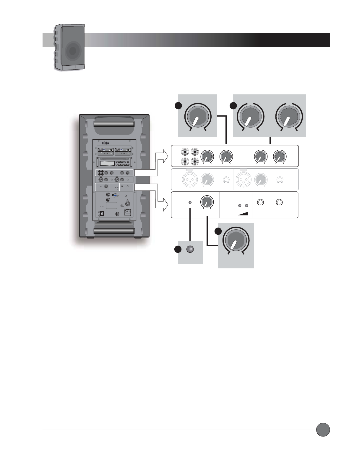
1. MASTER VOLUME: 1. MASTER VOLUME:
1. MASTER VOLUME: The MASTER VOLUME control is used to set the overall level of the audio going to the speaker(s).
1. MASTER VOLUME: 1. MASTER VOLUME:
Each individual input has its own level control, and all of these input signals are combined (mixed) into one signal that flows
through the MASTER VOLUME control.
2. LIMIT2. LIMIT
2. LIMIT
2. LIMIT2. LIMIT
: :
: The LIMIT LED lights up to indicate when the limiter is active. The limiter helps to prevent distortion which can
: :
cause damage to the speaker system. The level of the signals coming from the inputs (microphones, CD player , LINE IN) is
‘watched’ by the limiter circuit. The limiter instantly reduces the signal to a safe level if it becomes too large. When the limiter
light is on, the power amplifier has reached maximum power .
3. VOICE OVER MUSIC3. VOICE OVER MUSIC
3. VOICE OVER MUSIC: This is a special feature that automatically reduces the level of the LINE/CD inputs whenever sounds
3. VOICE OVER MUSIC3. VOICE OVER MUSIC
are produced at any of the four microphone inputs (WIRELESS MIC 1, WIRELESS MIC 2, MIC 1 IN, and MIC 2 IN). After a
few seconds of silence on the microphones, the LINE/CD signal will slowly return to its original volume level. This is handy
for events that require background music with occasional announcements.
The VOICE OVER MUSIC control sets the amount of reduction in level that occurs when the circuit is triggered by a microphone signal. For less reduction of the LINE/CD signal, turn the VOICE OVER MUSIC control clockwise. T o disable VOICE
OVER MUSIC, turn the control fully clockwise.
4. TONE CONTROLS4. TONE CONTROLS
4. TONE CONTROLS: The LOW and HIGH controls provide the ability to cut or boost the corresponding frequencies in the
4. TONE CONTROLS4. TONE CONTROLS
LINE/CD signal. These controls do not affect the microphone signals.
LightSPEED Technologies • Wireless Sound Solutions • Toll Free: 1-800-840-3662
11
Page 14
N
O
Operating Instructions
Wireless Microphones
7100R
UHF TRUE
DIVERSITY
RECEIVER
AB
RF
1
RF LED
Volume
SCAN SQ
Squelch
BATTERY
STATUS
2
VOL
MaxPWR Min
3
LOW CUT
LOW CUT
music speech
WIRELESS
MIC 1
music speech
WIRELESS
MIC 2
LOW OK
Delta X10
Sound System
WIRELESS MIC 1 WIRELESS MIC 2
VOL
7100R
UHF TRUE
DIVERSITY
LightSPEED
RECEIVER
MaxPWR Min
AB
CHANNEL
CHANNEL
LOW
RF
SCAN SQ
BAT
CD-ROM ART GOES HERE
NO
diSC
LINE/CD VOICE OVER MUSIC
LINE
I
N
O
U
-40 0
T
min max dB dB
LEVEL
IN
LOW CUT
MIC 1
musicspeech
min max
MASTER
BATTERY
VOLUME
STATUS
LIMIT
LOW OK
min max
LEVEL
EXTERNAL
SPEAKER A
SWITCHED
8 OHM
LightSPEED
EXTERNAL
SPEAKER B
MADE IN EUROPE
8 OHM
ON MUTE
POWER
DO NOT OPEN
ACTIVE
THE COVER.
LINK
REFER SERVICING
ON
TO QUALIFIED
PERSONNEL.
OFF
REPLACE FUSE
ONLY WITH
THE SAME TYPE
MUTE
AND RATING.
WIRELESS MICROPHONE OPERAWIRELESS MICROPHONE OPERA
WIRELESS MICROPHONE OPERA
WIRELESS MICROPHONE OPERAWIRELESS MICROPHONE OPERA
CHANNEL
LightSPEED
LOW
LIMIT
min max
Master Volume
BAT
4
Indicators
LEVEL
Knob
Wireless
VOL
7100R
UHF TRUE
DIVERSITY
LightSPEED
RECEIVER
MaxPWR Min
AB
LOW
RF
SCAN SQ
BAT
PROG
STOP PLAY/PAUSEA — BREPEAT
SCAN/SEARCH— SKIP —EJECT
TONE CONTROLLEVEL
0
0
–+
–+
LOW
HIGH
LEVEL
IN
LOW CUT
MIC 2
musicspeech
min max
LOW CUT
LOW CUT
musicspeech
musicspeech
WIRELESS
WIRELESS
MIC 1
MIC 2
CHARGING STATUS
EXTERNAL
POWER
SOURCE
12VDC/4A
4
1
3
2
GND
+ 12V
MAINS
AC
90-264V
47-63Hz
FUSE
T2A
TION TION
TION
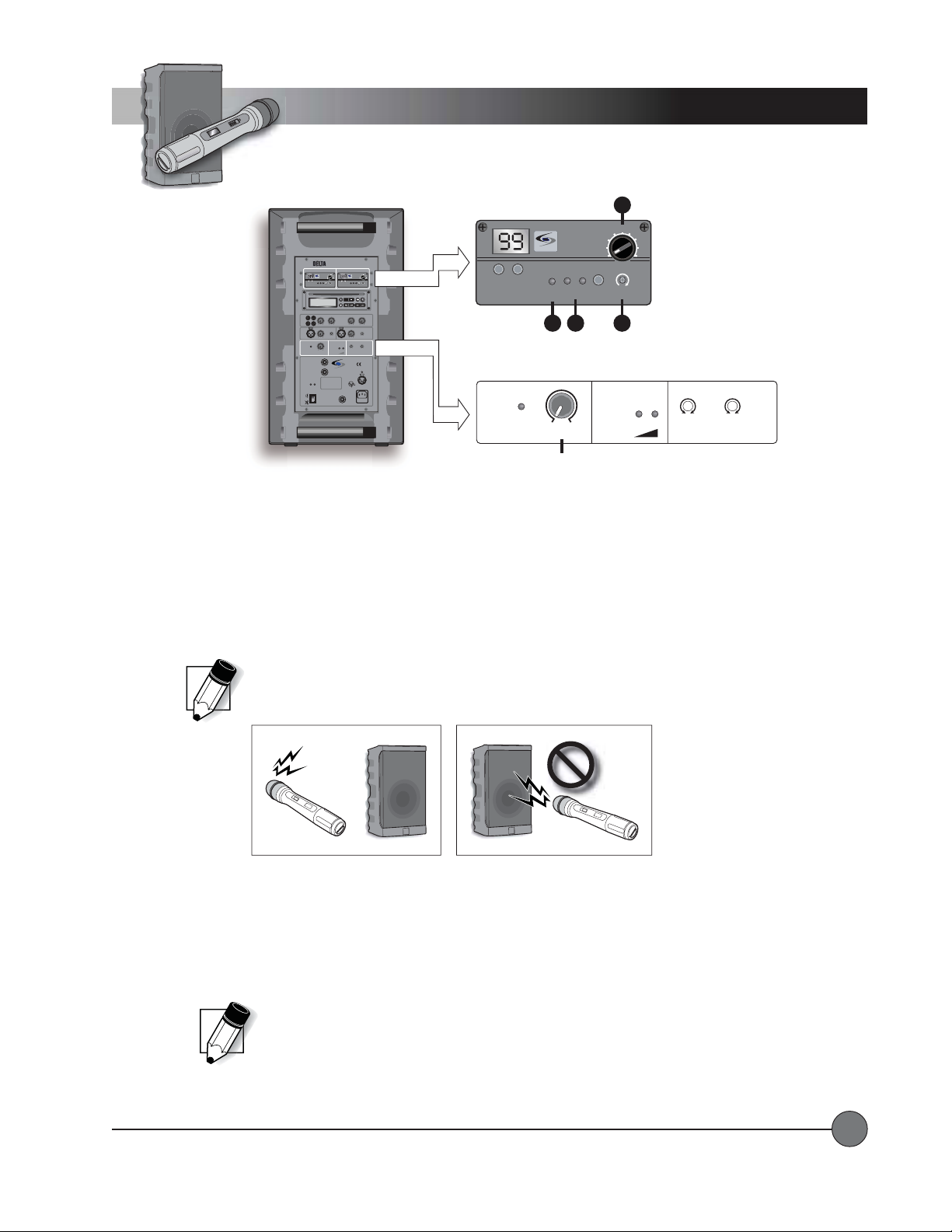
... detailed operating instructions for receivers and transmitters are provided later
TION TION
Low Battery LED
MASTER
VOLUME
in this manual.
1.1.
RF Indicator Lights:RF Indicator Lights:
1.
RF Indicator Lights: When both the system and the transmitter are on and operating on the same channel you will see
1.1.
RF Indicator Lights:RF Indicator Lights:
an RF Indicator Light (either A or B) on the receiver.
2.2.
VV
olume Adjustment:olume Adjustment:
2.
V
olume Adjustment: While speaking into the microphone, slowly turn the up the volume on the receiver (while paying
2.2.
VV
olume Adjustment:olume Adjustment:
attention to the MASTER VOLUME). Remember that if the MASTER VOLUME is turned all the way down, no sound will
come from the system regardless of the setting on the receiver volume.
NOTE: Do not stand directly in front of the DELTA X speaker with the microphone on. This will result in
feedback (‘squealing’ or ‘howling’). It is best to stand behind or off to the side of the unit when setting volume
level. Detailed information about setting up wireless receivers and transmitters is provided later in this manual.
3.3.
Squelch Adjustment: Squelch Adjustment:
3.
Squelch Adjustment: In areas that may have very high radio frequency traffic, it may be necessary to adjust the
3.3.
Squelch Adjustment: Squelch Adjustment:
squelch level to block out potential interference.
• Maximum squelch (full clockwise) reduces system reception range, but also reduces the
potential for system interference.
• Minimum squelch (full counterclockwise) increases reception range, but also increases
the potential for system interference.
NOTE: In most cases it will not be necessary to adjust the squelch level.
The Clear Channel Scan function will take care of most interference problems.
4.4.
TT
ransmitter Low Batterransmitter Low Batter
4.
T
ransmitter Low Batter
4.4.
TT
ransmitter Low Batterransmitter Low Batter
y Indicator:y Indicator:
y Indicator: This LED will light to indicate the batteries in the corresponding
y Indicator:y Indicator:
transmitter are low and need to be replaced or recharged.
LightSPEED Technologies • Wireless Sound Solutions • Toll Free: 1-800-840-3662
12
Page 15
Operating Instructions
Wired Microphone
1
IN
LIMIT
Volume Level
MIC 1 IN
Level
2
LEVEL
min max
min max
LEVEL
Master
LOW CUT
music speech
3
LOW CUT
music speech
BATTERY
STATUS
Wired Microphones
[dynamic or condenser]
Level
2
1
LEVEL
IN
min max
LOW CUT
music speech
LOW OK
WIRELESS
MIC 1
Delta X10
Wireless
Sound System
WIRELESS MIC 1 WIRELESS MIC 2
7100R
UHF TRUE
DIVERSITY
LightSPEED
RECEIVER
AB
CHANNEL
LOW
RF
SCAN SQ
BAT
CD-ROM ART GOES HERE
NO
diSC
LINE/CD VOICE OVER MUSIC
LINE
I
N
O
U
T
min max dB dB
LEVEL
IN
MIC 1
min max
MASTER
VOLUME
LIMIT
min max
LEVEL
EXTERNAL
SPEAKER A
SWITCHED
8 OHM
EXTERNAL
SPEAKER B
8 OHM
ON MUTE
POWER
DO NOT OPEN
THE COVER.
REFER SERVICING
ON
TO QUALIFIED
PERSONNEL.
OFF
REPLACE FUSE
ONLY WITH
THE SAME TYPE
MUTE
AND RATING.
WIRED MICROPHONE OPERAWIRED MICROPHONE OPERA
WIRED MICROPHONE OPERA
WIRED MICROPHONE OPERAWIRED MICROPHONE OPERA
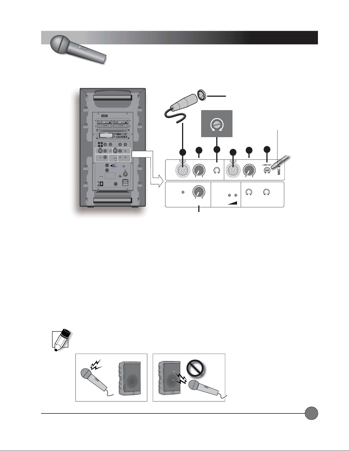
1.1.
MIC IN: MIC IN:
1.
MIC IN: Connect the wired microphone into one of the XLR input jacks labeled MIC 1 IN and MIC 2 IN.
1.1.
MIC IN: MIC IN:
VOL
VOL
7100R
UHF TRUE
DIVERSITY
LightSPEED
RECEIVER
MaxPWR Min
MaxPWR Min
AB
CHANNEL
LOW
RF
SCAN SQ
BAT
PROG
STOP PLAY/PAUSEA — BREPEAT
SCAN/SEARCH— SKIP —EJECT
TONE CONTROLLEVEL
0
0
-40 0
–+
–+
LOW
HIGH
LEVEL
IN
LOW CUT
LOW CUT
music speech
BATTERY
STATUS
LightSPEED
MADE IN EUROPE
MIC 2
music speech
min max
LOW CUT
LOW CUT
music speech
music speech
LOW OK
WIRELESS
WIRELESS
MIC 1
MIC 2
CHARGING STATUS
EXTERNAL
POWER
SOURCE
12VDC/4A
4
1
3
2
GND
+ 12V
MAINS
ACTIVE
AC
LINK
90-264V
47-63Hz
FUSE
T2A
TIONTION
TION
TIONTION
MIC 1
MASTER
VOLUME
Flat Blade
Screwdriver
Low Cut
3
music speech
LOW CUT
music speech
WIRELESS
MIC 2
2.2.
LEVEL: LEVEL:
2.
LEVEL: Rotate the level control clockwise to increase the volume (while paying attention to the MASTER VOLUME).
2.2.
LEVEL: LEVEL:
Remember that if the Master Volume is turned all the way down, no sound will come from the system regardless of the setting
on the MIC IN LEVEL.
3.3.
LOW CUT Filters: LOW CUT Filters:
3.
LOW CUT Filters: These adjustments allow you to reduce the level of the low frequencies on each wired microphone
3.3.
LOW CUT Filters: LOW CUT Filters:
input, making for a crisp and clear voice replication. The low cut filters affect only the associated wired microphone input.
They do not affect the overall tone of the Delta X system.
• To reduce the low frequency sounds (increase the low cut) turn the dial clockwise (towards “speech”) with a flat blade
screwdriver.
• If you desire a fuller sound for instruments or otherwise, turn the dial counterclockwise (towards “music”).
NOTE: Do not stand directly in front of the DEL TA X speaker with the microphone on. This will result in feedback
(‘squealing’ or ‘howling’). It is best to stand behind or off to the side of the unit when setting volume level.
Detailed information about setting up wireless receivers and transmitters is provided later in this manual.
LightSPEED Technologies • Wireless Sound Solutions • Toll Free: 1-800-840-3662
13
Page 16
WIRELESS MIC 1 WIRELESS MIC 2
VOL
7100R
UHF TRUE
DIVERSITY
LightSPEED
RECEIVER
AB
CHANNEL
LOW
RF
SCAN SQ
BAT
CD-ROM ART GOES HERE
NO
diSC
LINE/CD VOICE OVER MUSIC
LINE
I
N
O
U
-40 0
T
min max dB dB
LEVEL
IN
LOW CUT
MIC 1
music speech
min max
MASTER
BATTERY
VOLUME
STATUS
LIMIT
min max
LEVEL
EXTERNAL
SPEAKER A
SWITCHED
8 OHM
EXTERNAL
SPEAKER B
8 OHM
ON MUTE
POWER
DO NOT OPEN
THE COVER.
REFER SERVICING
ON
TO QUALIFIED
PERSONNEL.
OFF
REPLACE FUSE
ONLY WITH
THE SAME TYPE
MUTE
AND RATING.
Delta X10
Wireless
Sound System
7100R
UHF TRUE
DIVERSITY
LightSPEED
RECEIVER
MaxPWR Min
AB
CHANNEL
LOW
RF
BAT
STOP PLAY/PAUSEA — BREPEAT
TONE CONTROLLEVEL
0
–+
LOW
LEVEL
IN
min max
LOW CUT
music speech
LOW OK
WIRELESS
MIC 1
LightSPEED
MADE IN EUROPE
EXTERNAL
POWER
SOURCE
12VDC/4A
4
1
3
2
GND
+ 12V
MAINS
ACTIVE
AC
LINK
90-264V
47-63Hz
FUSE
T2A
SCAN SQ
SCAN/SEARCH— SKIP —EJECT
–+
LOW CUT
music speech
LOW CUT
music speech
WIRELESS
CHARGING STATUS
Operating Instructions
CD Player
VOL
MaxPWR Min
PROG
0
HIGH
MIC 2
MIC 2
Line IN
LINE
I
N
O
U
T
CD-ROM ART GOES HERE
NO
diSC
Voice
Line/CD
Level
LINE/CD VOICE OVER MUSIC
min max dB dB
Over
Music
1
2
-40 0
STOP PLAY/PAUSEA — BREPEAT
0
–+
LOW
Control
TONE CONTROLLEVEL
Tone
3
PROG
SCAN/SEARCH— SKIP —EJECT
0
–+
HIGH
CD PLACD PLA
CD PLA
CD PLACD PLA
YER OPERAYER OPERA
YER OPERA
YER OPERAYER OPERA
TIONTION
TION
TIONTION
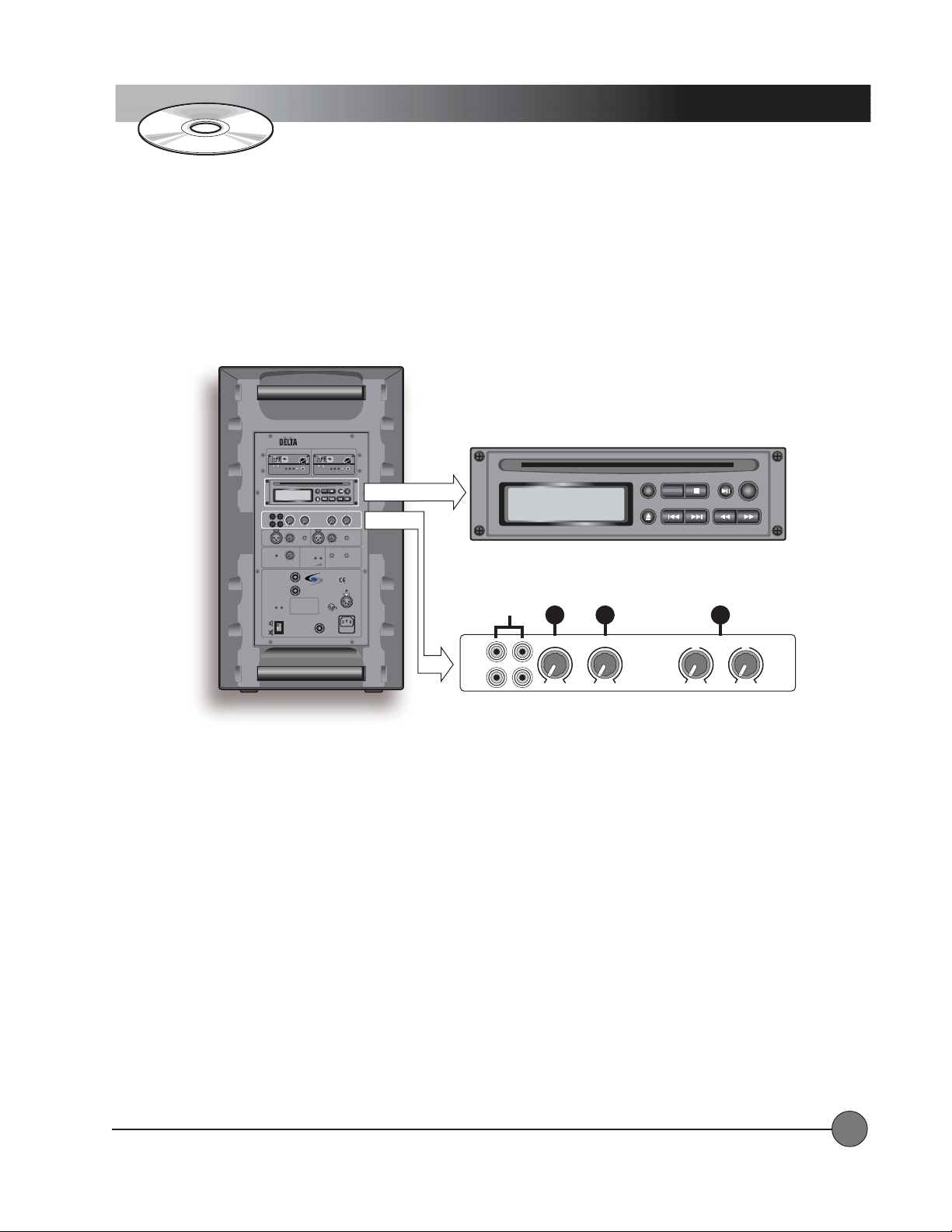
Note: Detailed information about using the CD player is provided later in this manual.
1.1.
VV
olume Adjustmenolume Adjustmen
1.
V
olume Adjustmen
1.1.
VV
olume Adjustmenolume Adjustmen
tt
t(LINE/CD LEVEL)
tt
::
: While playing a disc, slowly turn up the LINE/CD LEVEL control until you reach the
::
desired volume. Remember that if the MASTER VOLUME is turned all the way down, no sound will come from the system
regardless of the setting on the LINE/CD LEVEL control.
2.2.
VV
oice Prioritoice Priorit
2.
V
oice Priorit
2.2.
VV
oice Prioritoice Priorit
yy
y(VOICE OVER MUSIC)
yy
::
: Audio coming from the CD player and the LINE IN jacks will automatically drop in
::
level when sound is produced at any of the microphone inputs. When there is no more sound at the mic input(s), the audio
from the CD player and/or the LINE IN jacks will come back to its original level. Adjusting the VOICE OVER MUSIC control
changes the amount of drop in level that occurs when there is sound at the mic input(s).
3.3.
TT
one Controls:one Controls:
3.
T
one Controls: The LOW and HIGH tone controls can be used to cut or boost the lows and highs in the audio coming from
3.3.
TT
one Controls:one Controls:
the CD player and the LINE IN jacks. These controls do not affect the audio coming from the microphone inputs.
LightSPEED Technologies • Wireless Sound Solutions • Toll Free: 1-800-840-3662
14
Page 17
Operating Instructions
Active Link Operation
ON MUTE
POWER
1
WIRELESS MIC 1 WIRELESS MIC 2
VOL
7100R
UHF TRUE
DIVERSITY
LightSPEED
RECEIVER
AB
CHANNEL
LOW
RF
SCAN SQ
BAT
CD-ROM ART GOES HERE
NO
diSC
LINE/CD VOICE OVER MUSIC
LINE
I
N
O
U
-40 0
T
min max dB dB
LEVEL
IN
LOW CUT
MIC 1
music speech
min max
MASTER
BATTERY
VOLUME
STATUS
LIMIT
min max
LEVEL
EXTERNAL
SPEAKER A
SWITCHED
8 OHM
EXTERNAL
SPEAKER B
8 OHM
ON MUTE
POWER
DO NOT OPEN
THE COVER.
REFER SERVICING
ON
TO QUALIFIED
PERSONNEL.
OFF
REPLACE FUSE
ONLY WITH
THE SAME TYPE
MUTE
AND RATING.
ON
OFF
MUTE
MaxPWR Min
LightSPEED
MADE IN EUROPE
LOW OK
ACTIVE
LINK
Sound System
CHANNEL
REFER SERVICING
Wireless
7100R
UHF TRUE
DIVERSITY
LightSPEED
RECEIVER
AB
LOW
RF
SCAN SQ
BAT
STOP PLAY/PAUSEA — BREPEAT
SCAN/SEARCH— SKIP —EJECT
TONE CONTROLLEVEL
0
–+
LOW
LEVEL
IN
min max
LOW CUT
music speech
WIRELESS
MIC 1
CHARGING STATUS
EXTERNAL
POWER
SOURCE
12VDC/4A
4
1
3
2
GND
+ 12V
MAINS
AC
90-264V
47-63Hz
FUSE
T2A
DO NOT OPEN
THE COVER.
TO QUALIFIED
PERSONNEL.
REPLACE FUSE
ONLY WITH
THE SAME TYPE
AND RATING.
VOL
MaxPWR Min
PROG
0
–+
HIGH
LOW CUT
MIC 2
music speech
LOW CUT
music speech
WIRELESS
MIC 2
ACTIVE
LINK
2
4
Active Link
Ground Lift
Cable
3
Active Link
Cable
ON MUTE
POWER
1
ON
OFF
MUTE
DO NOT OPEN
THE COVER.
REFER SERVICING
TO QUALIFIED
PERSONNEL.
REPLACE FUSE
ONLY WITH
THE SAME TYPE
AND RATING.
LINE
I
N
O
U
T
MIC 1
MASTER
VOLUME
ACTIVE
LINK
2
Sound System
WIRELESS MIC 1 WIRELESS MIC 2
VOL
7100R
UHF TRUE
DIVERSITY
LightSPEED
RECEIVER
MaxPWR Min
AB
CHANNEL
CHANNEL
LOW
RF
SCAN SQ
BAT
CD-ROM ART GOES HERE
NO
diSC
LINE/CD VOICE OVER MUSIC
-40 0
min max dB dB
LEVEL
IN
LOW CUT
music speech
min max
BATTERY
STATUS
LIMIT
LOW OK
min max
LEVEL
EXTERNAL
SPEAKER A
SWITCHED
8 OHM
LightSPEED
EXTERNAL
SPEAKER B
MADE IN EUROPE
8 OHM
ON MUTE
POWER
DO NOT OPEN
ACTIVE
THE COVER.
LINK
REFER SERVICING
ON
TO QUALIFIED
PERSONNEL.
OFF
REPLACE FUSE
ONLY WITH
THE SAME TYPE
MUTE
AND RATING.
IN
Wireless
LightSPEED
LOW
–+
LOW
LEVEL
min max
LOW CUT
music speech
WIRELESS
MIC 1
EXTERNAL
POWER
SOURCE
12VDC/4A
4
3
MAINS
90-264V
47-63Hz
FUSE
VOL
7100R
UHF TRUE
DIVERSITY
RECEIVER
MaxPWR Min
AB
RF
SCAN SQ
BAT
PROG
STOP PLAY/PAUSEA — BREPEAT
SCAN/SEARCH— SKIP —EJECT
TONE CONTROLLEVEL
0
0
–+
HIGH
LOW CUT
MIC 2
music speech
LOW CUT
music speech
WIRELESS
MIC 2
CHARGING STATUS
1
2
GND
+ 12V
AC
T2A
Delta X #1 Delta X #2
CONNECTING TO ANOTHER DELCONNECTING TO ANOTHER DEL
CONNECTING TO ANOTHER DEL
CONNECTING TO ANOTHER DELCONNECTING TO ANOTHER DEL
TT
A X10 OR DELA X10 OR DEL
T
A X10 OR DEL
TT
A X10 OR DELA X10 OR DEL
TT
A X12A X12
T
A X12
TT
A X12A X12
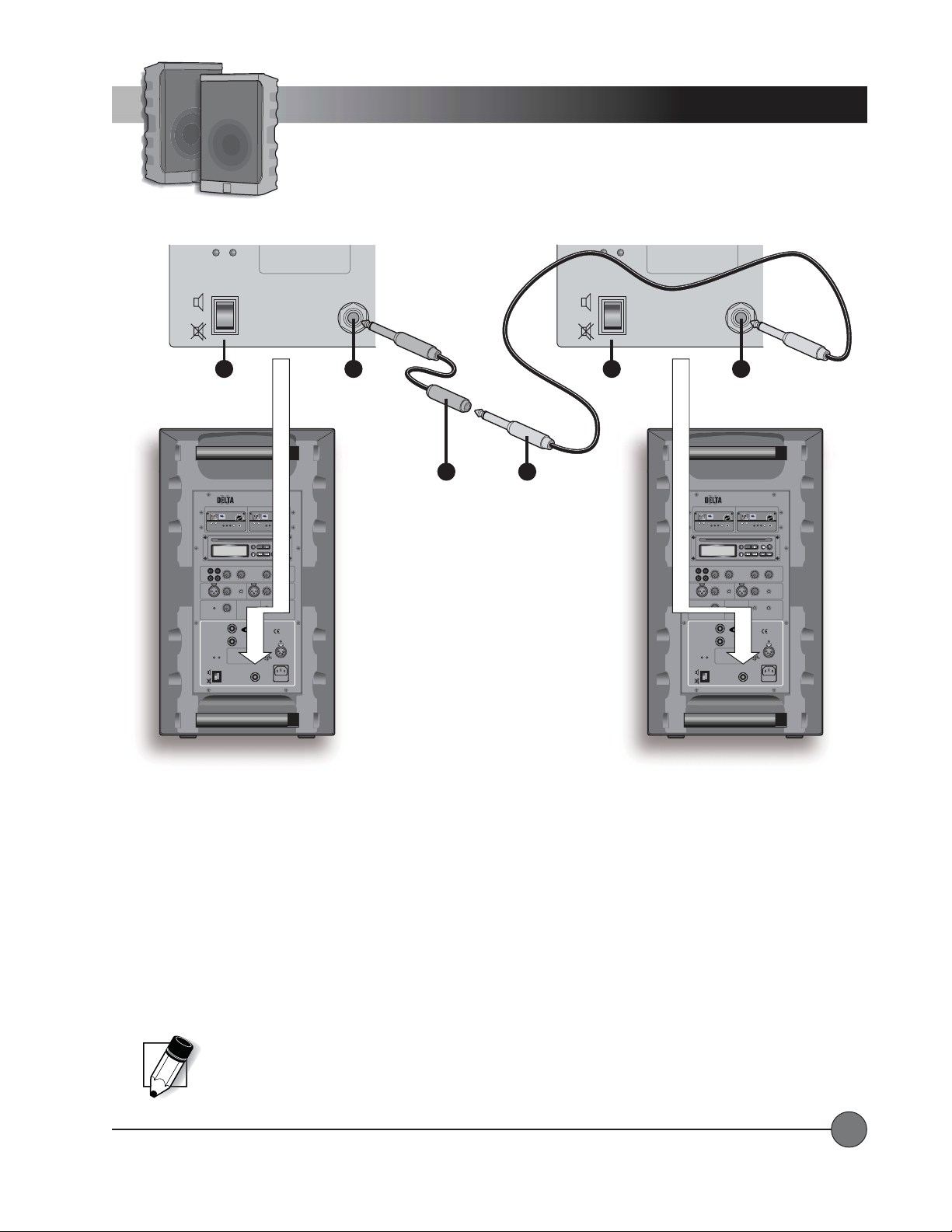
Using ACTIVE LINK, you can double the available inputs and double the sound level by connecting two Delta X10 or Delta X12
units together . When connected properly, the sound from both Delta X systems is ‘shared’ between them.
1.1.
System Power SwitchSystem Power Switch
1.
System Power Switch
1.1.
System Power SwitchSystem Power Switch
2.2.
Control panel Active Link jackControl panel Active Link jack
2.
Control panel Active Link jack
2.2.
Control panel Active Link jackControl panel Active Link jack
3.3.
Active Link CableActive Link Cable
3.
Active Link Cable
3.3.
Active Link CableActive Link Cable
4.4.
Active Link Ground Lift CableActive Link Ground Lift Cable
4.
Active Link Ground Lift Cable
4.4.
Active Link Ground Lift CableActive Link Ground Lift Cable
ACTIVE LINK cables are available from LightSPEED T echnologies in various lengths. Before connecting the ACTIVE LINK cable,
make sure the power to both Delta X systems is OFF. Put the Delta X systems in the locations that you have chosen, then
connect the ACTIVE LINK cable between them.
Note: If both Delta X systems are connected to AC mains power during operation, there may be an audible hum
in the audio. If this happens, you will need to connect an ACTIVE LINK GROUND LIFT cable (provided) to one of
the two Delta X units.
LightSPEED Technologies • Wireless Sound Solutions • Toll Free: 1-800-840-3662
15
Page 18
WIRELESS MIC 1 WIRELESS MIC 2
VOL
7100R
UHF TRUE
DIVERSITY
LightSPEED
RECEIVER
AB
CHANNEL
LOW
RF
SCAN SQ
BAT
CD-ROM ART GOES HERE
NO
diSC
LINE/CD VOICE OVER MUSIC
LINE
I
N
O
U
-40 0
T
min max dB dB
LEVEL
IN
LOW CUT
MIC 1
music speech
min max
MASTER
BATTERY
VOLUME
STATUS
LIMIT
min max
LEVEL
EXTERNAL
SPEAKER A
SWITCHED
8 OHM
EXTERNAL
SPEAKER B
8 OHM
ON MUTE
POWER
DO NOT OPEN
THE COVER.
REFER SERVICING
ON
TO QUALIFIED
PERSONNEL.
OFF
REPLACE FUSE
ONLY WITH
THE SAME TYPE
MUTE
AND RATING.
Delta X10
Wireless
Sound System
7100R
UHF TRUE
DIVERSITY
LightSPEED
RECEIVER
MaxPWR Min
AB
CHANNEL
LOW
RF
BAT
STOP PLAY/PAUSEA — BREPEAT
TONE CONTROLLEVEL
0
–+
LOW
LEVEL
IN
min max
LOW CUT
music speech
LOW OK
WIRELESS
MIC 1
LightSPEED
MADE IN EUROPE
EXTERNAL
POWER
SOURCE
12VDC/4A
4
1
3
2
GND
+ 12V
MAINS
ACTIVE
AC
LINK
90-264V
47-63Hz
FUSE
T2A
SCAN SQ
SCAN/SEARCH— SKIP —EJECT
–+
music speech
LOW CUT
music speech
WIRELESS
CHARGING STATUS
Operating Instructions
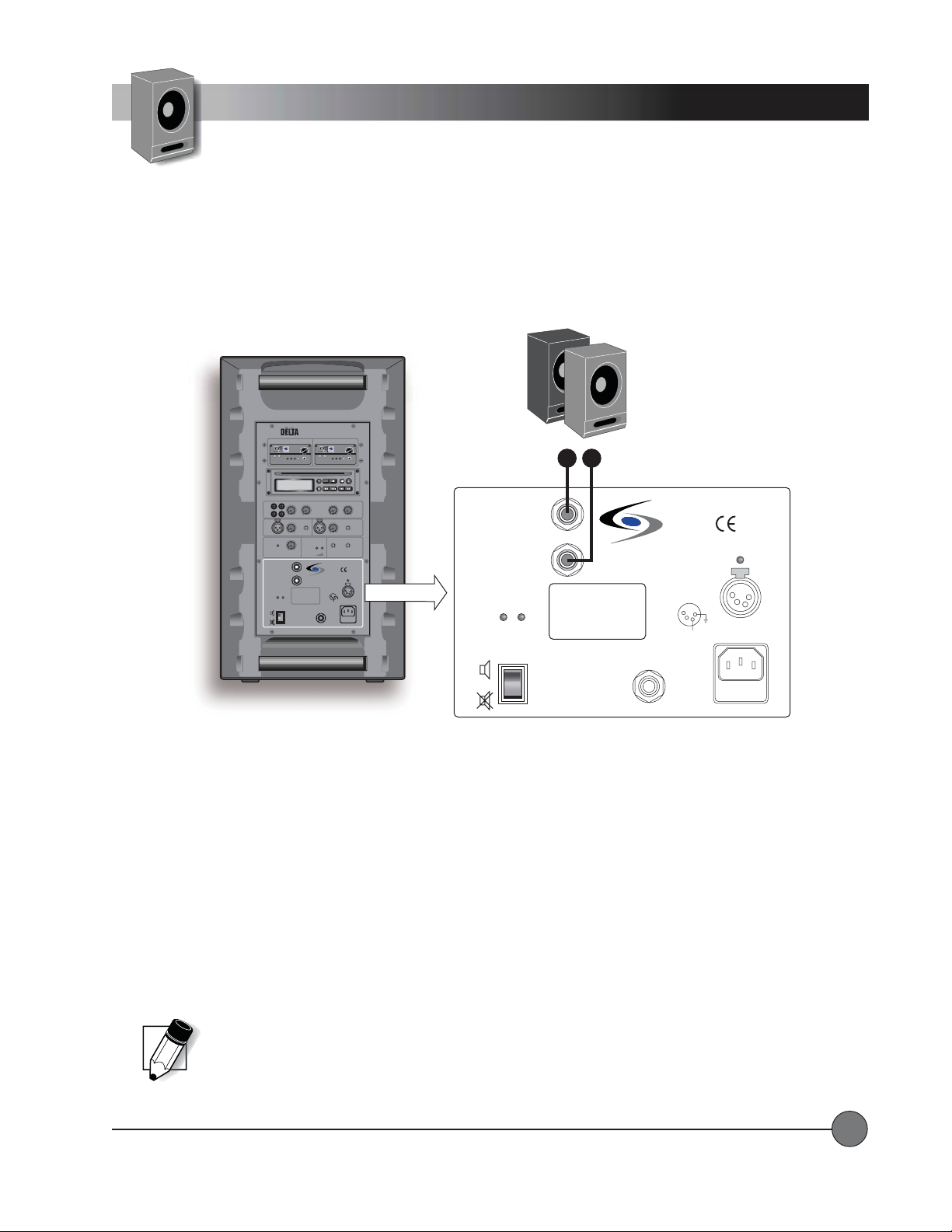
Connecting External Speakers
Output to
any 8Ω
speaker or
speaker
systems.
VOL
MaxPWR Min
PROG
0
HIGH
LOW CUT
MIC 2
MIC 2
EXTERNAL
SPEAKER A
SWITCHED
8 OHM
EXTERNAL
SPEAKER B
8 OHM
ON MUTE
POWER
ON
OFF
MUTE
1 2
DO NOT OPEN
THE COVER.
REFER SERVICING
TO QUALIFIED
PERSONNEL.
REPLACE FUSE
ONLY WITH
THE SAME TYPE
AND RATING.
LightSPEED
MADE IN EUROPE
ACTIVE
LINK
EXTERNAL
POWER
SOURCE
12VDC/4A
4
1
3
2
GND
+ 12V
MAINS
AC
90-264V
47-63Hz
FUSE
T2A
CHARGING STATUS
CONNECTING EXTERNAL SPEAKERSCONNECTING EXTERNAL SPEAKERS
CONNECTING EXTERNAL SPEAKERS
CONNECTING EXTERNAL SPEAKERSCONNECTING EXTERNAL SPEAKERS
The Delta X10 and Delta X12 systems have two internal power amplifiers to drive loudspeakers. One amplifier normally drives
the internal speaker and the other amplifier is dedicated for external passive speaker(s).
1. EXTERNAL SPEAKER A SWITCHED: When you connect an external speaker to this amplifier, the internal speaker will be
bypassed and only the external speaker will have sound.
2. EXTERNAL SPEAKER B: When you connect an external speaker to this amplifier, the internal speaker will continue to
produce sound along with the external speaker .
Each external speaker connection will handle a load impedance of 8 Ohms or higher . You can connect a single 8 Ohm speaker or
two 16 Ohm speakers in parallel to each external speaker output.
Note: If the amplifier output cuts out on loud sounds, check the impedance of the external speaker(s).
Loads of less than 8 Ohms will cause the amplifiers to shut down in order to prevent damage.
LightSPEED Technologies • Wireless Sound Solutions • Toll Free: 1-800-840-3662
16
Page 19
WIRELESS MIC 1 WIRELESS MIC 2
C
1
ma
LOW CUT
usic
sp
h
max
LOW CU
music
IN
VOL
7100R
UHF TRUE
DIVERSITY
LightSPEED
RECEIVER
AB
CHANNEL
LOW
RF
SCAN SQ
BAT
CD-ROM ART GOES HERE
NO
diSC
LINE/CD VOICE OVER MUSIC
LINE
I
N
O
U
-40 0
T
min max dB dB
LEVEL
IN
LOW CUT
MIC 1
music speech
min max
MASTER
BATTERY
VOLUME
STATUS
LIMIT
min max
LEVEL
EXTERNAL
SPEAKER A
SWITCHED
8 OHM
EXTERNAL
SPEAKER B
8 OHM
ON MUTE
POWER
DO NOT OPEN
THE COVER.
REFER SERVICING
ON
TO QUALIFIED
PERSONNEL.
OFF
REPLACE FUSE
ONLY WITH
THE SAME TYPE
MUTE
AND RATING.
Delta X10
Wireless
Sound System
7100R
UHF TRUE
DIVERSITY
LightSPEED
RECEIVER
MaxPWR Min
AB
CHANNEL
LOW
RF
BAT
STOP PLAY/PAUSEA — BREPEAT
TONE CONTROLLEVEL
0
–+
LOW
LEVEL
IN
min max
LOW CUT
music speech
LOW OK
WIRELESS
MIC 1
LightSPEED
MADE IN EUROPE
EXTERNAL
POWER
SOURCE
12VDC/4A
4
1
3
2
GND
+ 12V
MAINS
ACTIVE
AC
LINK
90-264V
47-63Hz
FUSE
T2A
SCAN SQ
SCAN/SEARCH— SKIP —EJECT
–+
LOW CUT
music speech
LOW CUT
music speech
WIRELESS
CHARGING STATUS
Operating Instructions
External Audio IN/OUT
Line/CD Level
1
LINE/CD VOICE OVER MUSIC
min max dB dB
IN
min max
LEVEL
2
TONE CONTROLLEVEL
-40 0
x
m
eec
BATTERY
STATUS
LOW OK
0
–+
LOW
LOW CUT
music speech
WIRELESS
MIC 1
0
–+
HIGH
T
speech
LOW CUT
music speech
WIRELESS
MIC 2
MIC 2
Line IN
VOL
MaxPWR Min
PROG
0
HIGH
MIC 2
MIC 2
LINE
I
N
O
U
T
MI
MASTER
VOLUME
LIMIT
Master Volume
Knob
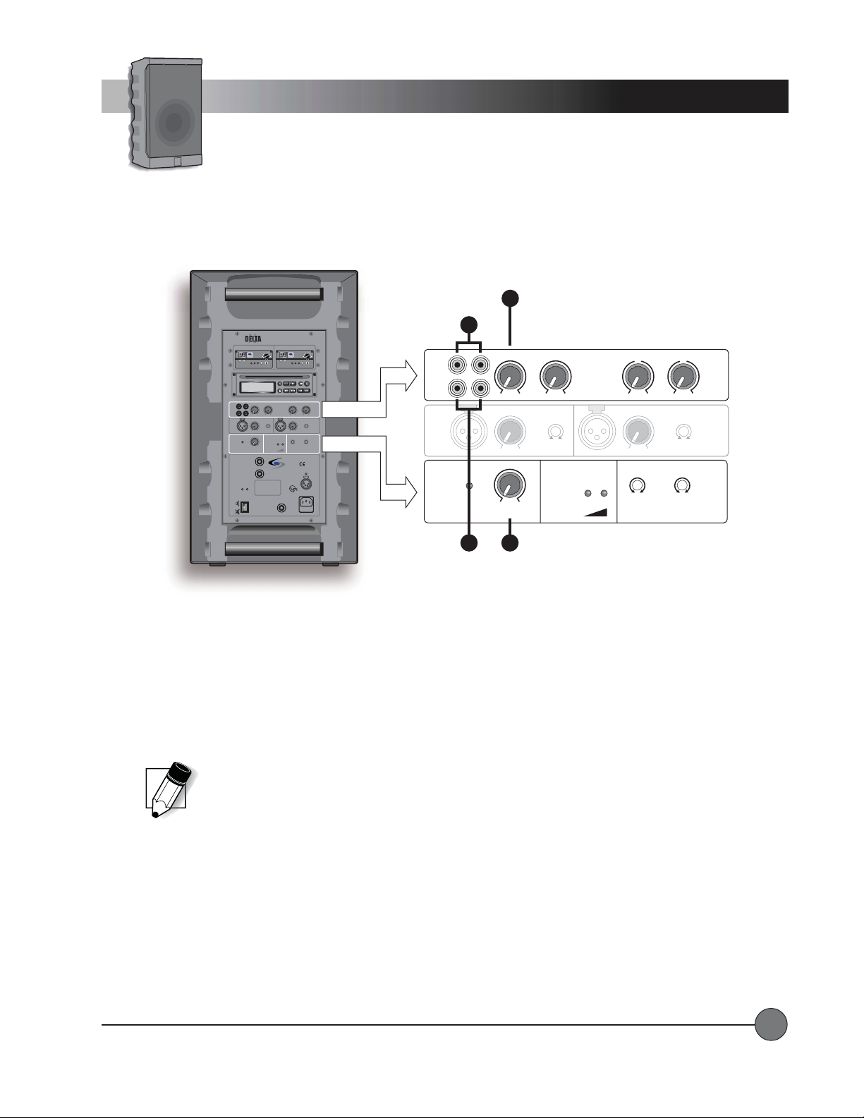
CONNECTING EXTERNAL AUDIO SOURCESCONNECTING EXTERNAL AUDIO SOURCES
CONNECTING EXTERNAL AUDIO SOURCES
CONNECTING EXTERNAL AUDIO SOURCESCONNECTING EXTERNAL AUDIO SOURCES
Line
OUT
3 4
T o connect an external audio source such as an MP3 Player, CD/DVD, TV/VCR, or computer to the Delta X system:
1.1.
LINE IN: LINE IN:
1.
LINE IN: Connect a cable from an audio source to the RCA jack(s) labeled LINE IN. Stereo sources will be summed into
1.1.
LINE IN: LINE IN:
a mono signal within the Delta X system.
2.2.
LINE/CD LEVEL: LINE/CD LEVEL:
2.
LINE/CD LEVEL: With the unit turned ON, adjust the LINE/CD Level volume knob to a desired level.
2.2.
LINE/CD LEVEL: LINE/CD LEVEL:
NOTE: When hooking up auxiliary equipment, you may
need an adaptor depending on the connections available.
CONNECTING AUDIO OUTPUT TO EXTERNAL DEVICESCONNECTING AUDIO OUTPUT TO EXTERNAL DEVICES
CONNECTING AUDIO OUTPUT TO EXTERNAL DEVICES
CONNECTING AUDIO OUTPUT TO EXTERNAL DEVICESCONNECTING AUDIO OUTPUT TO EXTERNAL DEVICES
T o output the mixed audio signal of the Delta X system to an external device such as a recording device, mixing console, or
assistive listening transmitter:
3.3.
LINE OUTLINE OUT
3.
LINE OUT
3.3.
LINE OUTLINE OUT
: :
: Connect a cable from the RCA jack(s) labeled LINE OUT to the external device. Both RCA jacks contain the
: :
same mono signal.
4.4.
MASTER VOLUME: MASTER VOLUME:
4.
MASTER VOLUME: The RCA jacks provide a line-level output signal that does not change volume regardless of the
4.4.
MASTER VOLUME: MASTER VOLUME:
setting on the MASTER VOLUME control.
LightSPEED Technologies • Wireless Sound Solutions • Toll Free: 1-800-840-3662
17
Page 20
CHANNEL
VOL
7100R
UHF TRUE
DIVERSITY
LightSPEED
RECEIVER
LOW
BAT
AB
RF
SCAN SQ
MaxPWR Min
Operating Instructions
Wireless Receiver(s)
WIRELESS MIC 1 WIRELESS MIC 2
VOL
7100R
UHF TRUE
DIVERSITY
LightSPEED
RECEIVER
AB
CHANNEL
LOW
RF
SCAN SQ
BAT
CD-ROM ART GOES HERE
NO
diSC
LINE/CD VOICE OVER MUSIC
LINE
I
N
O
U
-40 0
T
min max dB dB
LEVEL
IN
LOW CUT
MIC 1
music speech
min max
MASTER
BATTERY
VOLUME
STATUS
LIMIT
min max
LEVEL
EXTERNAL
SPEAKER A
SWITCHED
8 OHM
EXTERNAL
SPEAKER B
8 OHM
ON MUTE
POWER
DO NOT OPEN
THE COVER.
REFER SERVICING
ON
TO QUALIFIED
PERSONNEL.
OFF
REPLACE FUSE
ONLY WITH
THE SAME TYPE
MUTE
AND RATING.
Delta X10
Wireless
Sound System
7100R
UHF TRUE
DIVERSITY
LightSPEED
RECEIVER
MaxPWR Min
AB
CHANNEL
LOW
RF
BAT
STOP PLAY/PAUSEA — BREPEAT
TONE CONTROLLEVEL
0
–+
LOW
LEVEL
IN
min max
LOW CUT
music speech
LOW OK
WIRELESS
MIC 1
LightSPEED
MADE IN EUROPE
EXTERNAL
POWER
SOURCE
12VDC/4A
4
1
3
2
GND
+ 12V
MAINS
ACTIVE
AC
LINK
90-264V
47-63Hz
FUSE
T2A
SCAN SQ
SCAN/SEARCH— SKIP —EJECT
–+
LOW CUT
music speech
LOW CUT
music speech
WIRELESS
CHARGING STATUS
AB
RF
SCAN
DO NOT OPEN
THE COVER.
REFER SERVICING
TO QUALIFIED
Volume
SCAN SQ
5
LightSPEED
MADE IN EUROPE
3
VOL
MaxPWR Min
ACTIVE
LINK
EXTERNAL
POWER
SOURCE
12VDC/4A
4
1
3
2
GND
+ 12V
MAINS
AC
90-264V
47-63Hz
FUSE
T2A
CHARGING STATUS
Frequency Group
4
7100R
UHF TRUE
DIVERSITY
LightSPEED
RECEIVER
CHANNEL
VOL
MaxPWR Min
PROG
0
HIGH
MIC 2
MIC 2
Manual Channel
Select Buttons
2
LOW
EXTERNAL
SPEAKER A
SWITCHED
8 OHM
EXTERNAL
SPEAKER B
8 OHM
ON MUTE
POWER
ON
1
BAT
DETDET
AILED OPERAAILED OPERA
DET
AILED OPERA
DETDET
AILED OPERAAILED OPERA
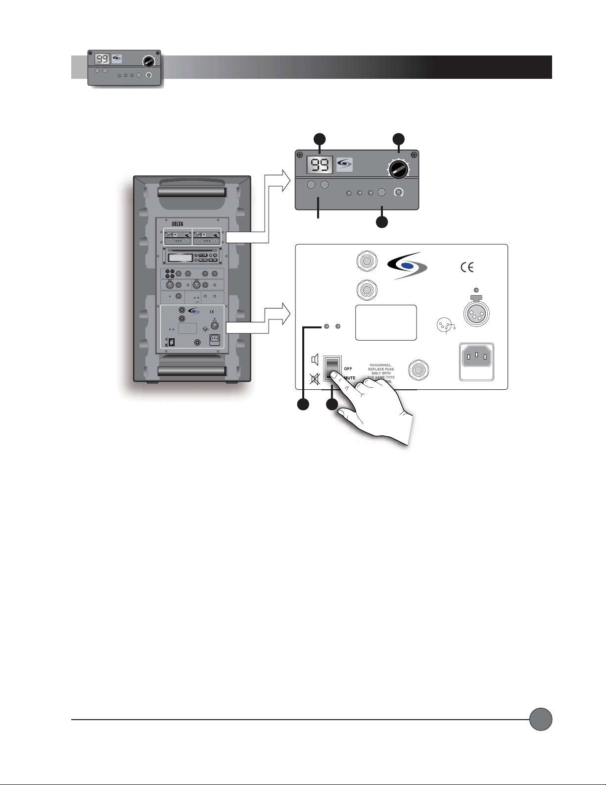
Power up the Delta X system and wireless receiver(s)Power up the Delta X system and wireless receiver(s)
Power up the Delta X system and wireless receiver(s)
Power up the Delta X system and wireless receiver(s)Power up the Delta X system and wireless receiver(s)
1.1.
POWER:POWER:
1.
POWER: Push the POWER switch on the base unit back panel to the ON (or MUTE) position.
1.1.
POWER:POWER:
2.2.
ON LED:ON LED:
2.
ON LED: The ON LED will light.
2.2.
ON LED:ON LED:
3.3.
Receiver VReceiver V
3.
Receiver V
3.3.
Receiver VReceiver V
TION - WIRELESS RECEIVERTION - WIRELESS RECEIVER
TION - WIRELESS RECEIVER
TION - WIRELESS RECEIVERTION - WIRELESS RECEIVER
olume:olume:
olume: Rotate the Power/Volume knob on the receiver module clockwise to turn on.
olume:olume:
Leave the volume at a low
level for now.
4.4.
Frequency Group:Frequency Group:
4.
Frequency Group: When the receiver power is first switched on, the frequency group of the receiver will be shown briefly
4.4.
Frequency Group:Frequency Group:
as letters on the LED display.
Channel Selection - Wireless ReceiverChannel Selection - Wireless Receiver
Channel Selection - Wireless Receiver
Channel Selection - Wireless ReceiverChannel Selection - Wireless Receiver
(See frequency group chart on page 30)
Each receiver has 100 user-selectable channels to choose from. You can select a channel either manually or by pressing the
SCAN button which will automatically select a clear channel.
5.5.
Clear Channel Scan (Recommended): Clear Channel Scan (Recommended):
5.
Clear Channel Scan (Recommended): Make sure the transmitter(s) is OFF before pressing this button. When this button
5.5.
Clear Channel Scan (Recommended): Clear Channel Scan (Recommended):
is pressed, the receiver will cycle through all 100 channels and select a clear frequency (this process takes about 20
seconds). Once the receiver selects the clear channel, you will need to select the same channel on the corresponding
transmitter (handheld or belt-pack).
If YIf Y
ou Have a Second Receiver (WIRELESS MIC 2):ou Have a Second Receiver (WIRELESS MIC 2):
If Y
ou Have a Second Receiver (WIRELESS MIC 2): Verify that WIRELESS MIC 1 is operating on a clear channel, and the
If YIf Y
ou Have a Second Receiver (WIRELESS MIC 2):ou Have a Second Receiver (WIRELESS MIC 2):
transmitter for WIRELESS MIC 1 is turned ON. Make sure the transmitter for WIRELESS MIC 2 is turned OFF, and then press the
“SCAN” button on the WIRELESS MIC 2 receiver . After the WIRELESS MIC 2 receiver selects a clear channel, set the WIRELESS
MIC 2 transmitter (handheld or belt-pack) to the selected channel.
LightSPEED Technologies • Wireless Sound Solutions • Toll Free: 1-800-840-3662
18
Page 21
VOL
7100R
UHF TRUE
DIVERSITY
LightSPEED
RECEIVER
CHANNEL
LOW
BAT
MANUAL CHANNEL SELECTION:MANUAL CHANNEL SELECTION:
MANUAL CHANNEL SELECTION:
MANUAL CHANNEL SELECTION:MANUAL CHANNEL SELECTION:
6.6.
Left Channel Button: Left Channel Button:
6.
Left Channe l Button: Pressing the Left Channel button changes the
6.6.
Left Channel Button: Left Channel Button:
AB
RF
MaxPWR Min
SCAN SQ
first number (0-9).
7.7.
Right Channel Button:Right Channel Button:
7.
Right Channel Button: Pressing the Right Channel button changes
7.7.
Right Channel Button:Right Channel Button:
the second number (0-9). Once a frequency is selected, you will
need to select the same channel on the corresponding transmitter
(handheld or belt-pack).
NOTE: There are 5 different groupings of 100 channels
available, which are sent out to maximize clear channels
in a specific geography. When the system is powered on,
the two letters that initially blink in the Channel window on
the receiver indicate the frequency group
(see chart on page 30 for further details).
Operating Instructions
Wireless Receiver(s)
100-channel UHF Receiver Module
VOL
SCAN SQ
8
CHANNEL
6 7
LightSPEED
LOW
BAT
7100R
UHF TRUE
DIVERSITY
RECEIVER
AB
RF
MaxPWR Min
8.8.
SQUELCH ADJUSTMENTSQUELCH ADJUSTMENT
8.
SQUELCH ADJUSTMENT
8.8.
SQUELCH ADJUSTMENTSQUELCH ADJUSTMENT
::
: In areas that have very high radio frequency traffic, it may be necessary to adjust the squelch level
::
to block out potential interference.
••
MAXIMUM SQUELCH:MAXIMUM SQUELCH:
•
MAXIMUM SQUELCH: (full clockwise) reduces the system reception range, but also reduces the potential for radio
••
MAXIMUM SQUELCH:MAXIMUM SQUELCH:
frequency interference.
••
MINIMUM SQUELCH:MINIMUM SQUELCH:
•
MINIMUM SQUELCH: (full counterclockwise) maximizes reception range, but also increases the potential for radio
••
MINIMUM SQUELCH:MINIMUM SQUELCH:
frequency interference.
Installing or Replacing a Receiver Module:Installing or Replacing a Receiver Module:
Installing or Replacing a Receiver Module:
Installing or Replacing a Receiver Module:Installing or Replacing a Receiver Module:
Delta X system is turned OFF.
Remove the two screws securing the module
Make sure the power to the
or filler panel using a small Phillips screwdriver . To remove the module,
use a small flat-blade screwdriver . Carefully insert the blade under the face
plate edge and nudge it outward. Grasp the edges with both hands and slide
outward. Install the new module by aligning it with the guide rails and sliding
all the way in to engage the connector at the rear of the module.
Replace the two screws.
LightSPEED Technologies • Wireless Sound Solutions • Toll Free: 1-800-840-3662
Remove
Screw
CHANNEL
LightSPEED
Remove
Screw
RF
VOL
MaxPWR Min
SCAN SQ
7100R
UHF TRUE
DIVERSITY
RECEIVER
AB
LOW
BAT
19
Page 22
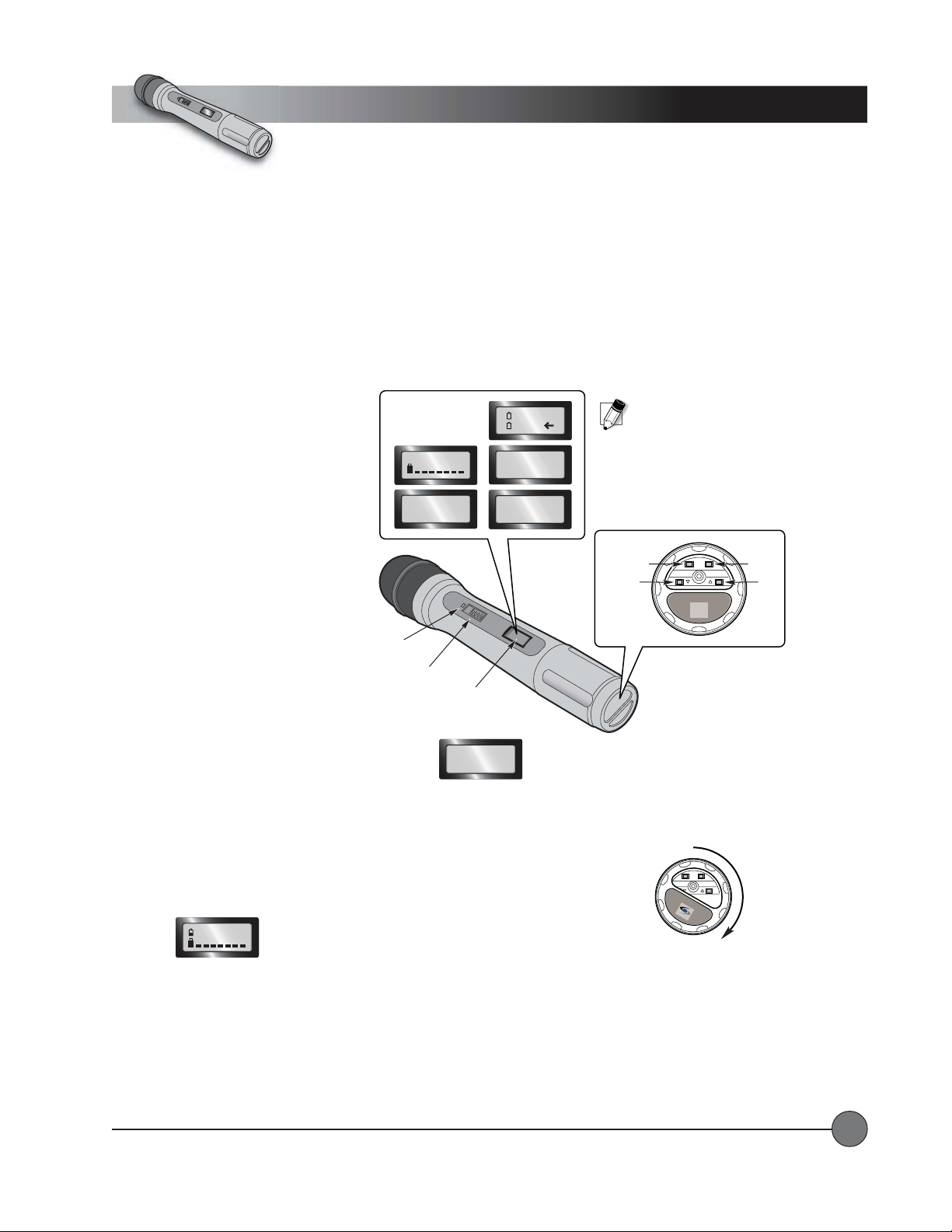
N
O
Operating Instructions
Wireless Transmitter
Handheld Microphone
Channel Selection – Handheld TChannel Selection – Handheld T
Channel Selection – Handheld T
Channel Selection – Handheld TChannel Selection – Handheld T
ransmitterransmitter
ransmitter
ransmitterransmitter
Once a channel has been selected on the receiver , you now need to select that same channel on the handheld transmitter.
have a belt-pack transmitter, go to page 23 for channel selection instructions.
•Turn the microphone on by sliding
the switch on the barrel to the ON
position. The red LED will flash once.
•Use the “up” and “down” buttons to
select a screen that shows the current
channel.
•To change the channel, press and hold
Setup Screens
selectable with
the UP and DOWN
Arrow Buttons
CH: 002
CH: 002
720.500M
NiMH
AKLN
SENS SET
LEVEL [2]
LS
HM-900
NOTE: Transmitters and receivers
are available in 5 different frequency
groups. Ver ify that the letter code that
blinks on the receiver (when powered
ON) matches the letter code on the
frequency sticker in the battery
compartment of the transmitter.
the “SET” button on the bottom of the
microphone until there is a blinking
cursor on the LCD display
window
(approximately 3 seconds).
LOCK
DOWN
ON
LOCK SET
HM-900
SET
UP
•Use the “UP” and “DOWN” buttons to
set the channel to match the receiver .
•Press and hold the “SET” button again
until the blinking cursor disappears
and the red LED flashes
(approximately 3 seconds).
TT
ransmission Frequency in MHz: ransmission Frequency in MHz:
T
ransmission Frequency in MHz: Press the “UP”
TT
ransmission Frequency in MHz: ransmission Frequency in MHz:
button once to view the transmission frequency in
Red
LED
ON/OFF
Switch
LCD
Display
CH: 002
720.500M
MHz of the currently selected channel.
If you
Lock FunctionLock Function
Lock Function
Lock FunctionLock Function
This allows users to lock out all the controls on the microphone so that it is not accidentally switched off or the channels aren’t
accidentally changed in the middle of a performance.
T o lock all the controls:
•Press the “LOCK” button on the bottom of the microphone. A lock icon
will appear on the LCD screen next to the channel number .
CH: 002
•The black
(or colored)
disc on the bottom can be rotated around to completely cover the controls so that the buttons
LOCK SET
HM-900
L
ig
h
tS
P
E
E
D
Rotate Disc to Secure
Controls
cannot be accidentally pressed again.
T o unlock all the controls:
•Rotate the black
(or colored)
disc back around to reveal the buttons on the bottom of the microphone.
•Press the “LOCK” button again to unlock. The lock icon will disappear.
LightSPEED Technologies • Wireless Sound Solutions • Toll Free: 1-800-840-3662
20
Page 23
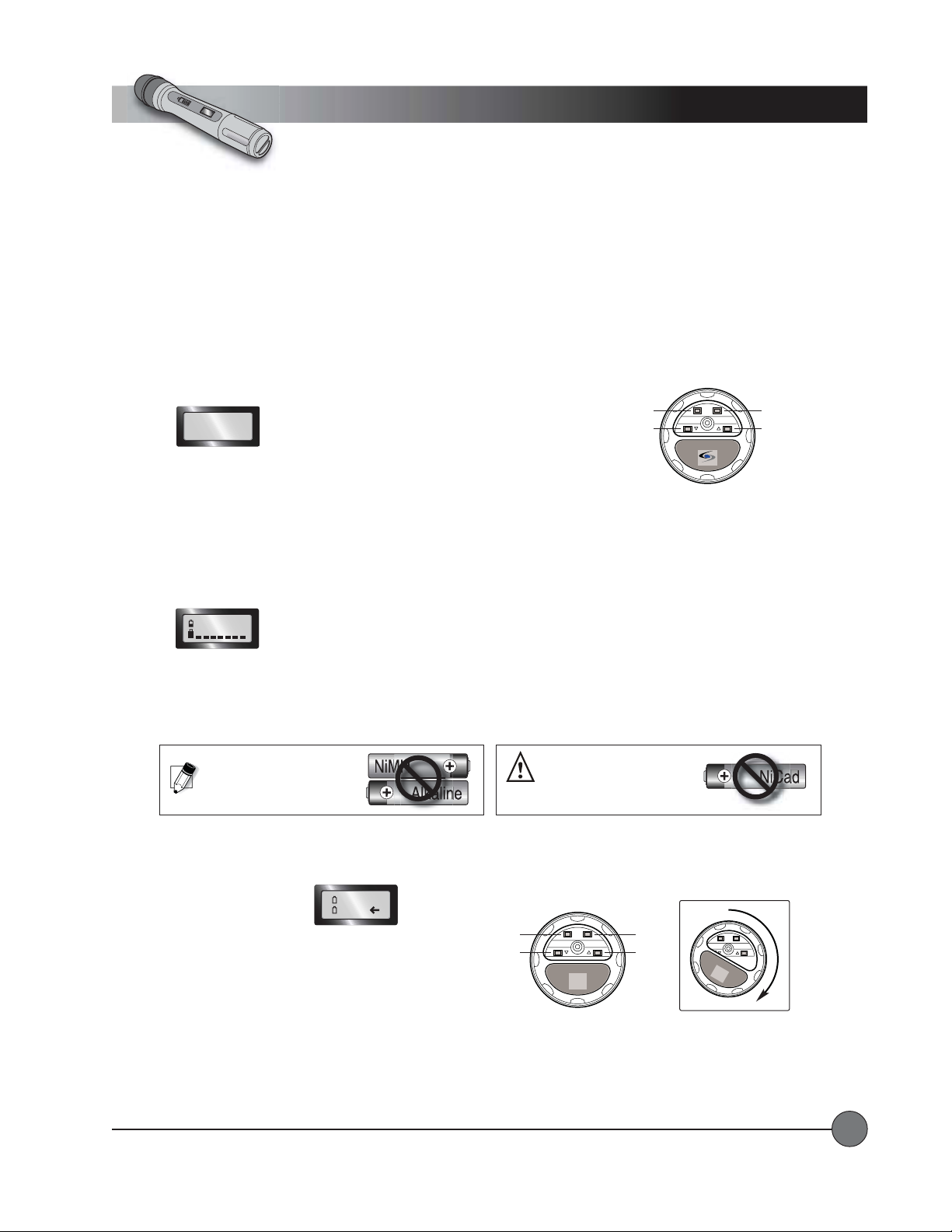
LOCK SET
HM-900
SET
UP
DOWN
LOCK
Handheld Microphone
End View
LightSPEED
N
O
Operating Instructions
Wireless Transmitter
Handheld Microphone
Sensitivity LevelSensitivity Level
Sensitivity Level
Sensitivity LevelSensitivity Level
This function allows the user to set the gain structure of the microphone to best fit the voice level of the person speaking into it.
A person with a very loud, booming voice may want the microphone set to a sensitivity level of 1 or 2. A person with a very soft
voice will be better off with the microphone set to a sensitivity of 3 or 4.
T o change the sensitivity setting:
•Press the “UP” button 3 times to get to the Sensitivity Level screen.
SENS SET
LEVEL [2]
•Press and hold the “SET” button until ablinking cursor appears.
•Use the “UP” and “DOWN” arrows to make a selection (1-4).
•Press and hold the “SET” button again until the blinking cursor disappears.
BatterBatter
y Life Indicatory Life Indicator
Batter
y Life Indicator
BatterBatter
y Life Indicatory Life Indicator
The battery life is shown on the primary screen of the LCD. The 7-step fuel gauge acts as a detailed guide to show the actual life
of the battery.
CH: 002
BatterBatter
y Ty T
y T
y Ty T
ypeype
ype
ypeype
Batter
BatterBatter
The transmitter will operate with either standard Alkaline Batteries or Nickel Metal Hydride (NiMH) Rechargable Batteries. Since
these types of batteries have different characteristics, it is important to set the transmitter to the appropriate type of battery being
used so that the battery life indicator will operate properly.
WARNING: Do not use NiCad
NOTE: Do not mix batter y types.
TT
o Change the Battero Change the Batter
T
o Change the Batter
TT
o Change the Battero Change the Batter
y Ty T
ype Setting:ype Setting:
y T
ype Setting:
y Ty T
ype Setting:ype Setting:
batteries! They will not charge
properly and may cause damage
to the transmitter.
•Press the “UP” button
twice to get to the
battery-type screen.
•Press and hold the “SET” button until a blinking
cursor appears.
NiMH
AKLN
LOCK
DOWN
LOCK SET
HM-900
SET
UP
LOCK SET
HM-900
•Use the “UP” and “DOWN” arrows to make a selection.
Rotate Disc to Secure
Controls
•Press and hold the “SET” button again until the
Handheld Microphone
End View
blinking cursor disappears.
LightSPEED Technologies • Wireless Sound Solutions • Toll Free: 1-800-840-3662
21
Page 24
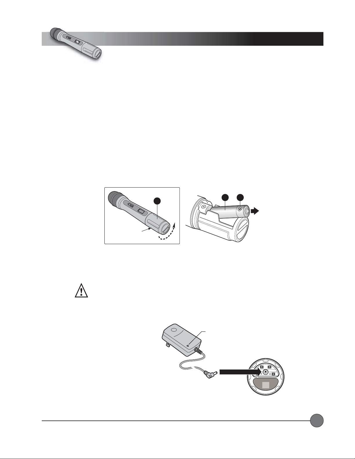
e
N
O
Operating Instructions
Wireless Transmitter
Handheld Microphone
REPLACING THE BAREPLACING THE BA
REPLACING THE BA
REPLACING THE BAREPLACING THE BA
1.1.
1. To replace the batteries, unscrew the end cap to reveal the battery compartment.
1.1.
2.2.
2. Remove or replace the batteries as shown. The microphone requires two AA sized batteries stacked end to end.
2.2.
3.3.
3. Note the polarity in the battery compartment.
3.3.
TTERIESTTERIES
TTERIES
TTERIESTTERIES
Typical battery life is about 8 hours.
IMPORTANT! Replace batter ies with the same type, (alkaline or NiMH),
that were installed in your handheld microphone.
2
3
CHARGING THE BACHARGING THE BA
CHARGING THE BA
CHARGING THE BACHARGING THE BA
ON
End Cap
TTERIES (NiMH Rechargeable Batteries ONLTTERIES (NiMH Rechargeable Batteries ONL
TTERIES (NiMH Rechargeable Batteries ONL
TTERIES (NiMH Rechargeable Batteries ONLTTERIES (NiMH Rechargeable Batteries ONL
1
Y)Y)
Y)
Y)Y)
Make sure there are NiMH Rechargeable Batteries in the transmitter before plugging in the charger .
WARNING: Do not attempt to charge alkaline batteries. They can
overheat and expand, creating a significant hazard and damaging
the transmitter.
(This is not covered by warranty.)
•Switch the transmitter power off.
•Insert the small DC plug
into the jack on the bottom
of the transmitter .
•Plug the other end of the charger
into any standard 110 VAC outlet.
Transmitter
Charger
•The Red LED on the charger will light
indicating that charging is in progress.
•When the batteries are fully charged,
the light on the charger will turn green.
A full charge can take up to 8 hours.
LightSPEED Technologies • Wireless Sound Solutions • Toll Free: 1-800-840-3662
Charger
Connector
Charger Status LED
• RED = charging in progress
• GREEN = batteries fully charged
Handheld Microphon
End View
LOCK SET
HM-900
22
Page 25
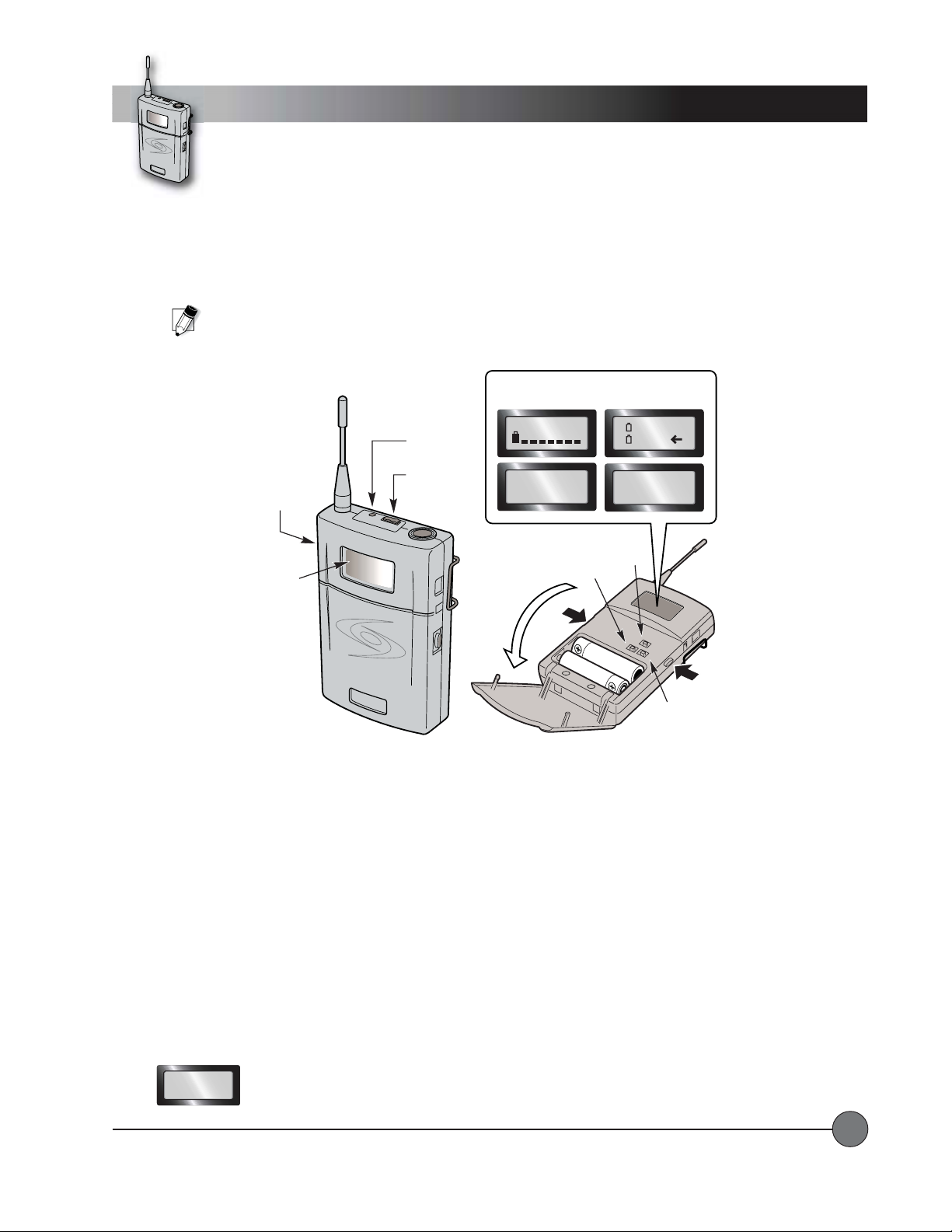
Operating Instructions
LightSPE
E
D
Wireless Transmitter
Belt-pack
Channel Selection – Belt-pack TChannel Selection – Belt-pack T
Channel Selection – Belt-pack T
Channel Selection – Belt-pack TChannel Selection – Belt-pack T
Once a channel has been selected on the receiver , you now need to select that same channel on the belt pack transmitter.
NOTE: Transmitters and receivers are available in 5 different frequency groups. Ver ify that the letter code that blinks
on the receiver (when powered ON) matches the letter code on the frequency sticker in the battery compartment of
the transmitter.
ON/OFF
Switch
LCD
Display
ransmitterransmitter
ransmitter
ransmitterransmitter
Red LED
Mute
Button
Setup Screens selectable with
the UP and DOWN Arrow Buttons
CH: 001
CH: 001
720. 250M
Toggle
NiMH
AKLN
LS
BP-900
Set
UP
LightSPEED
Door
Latch
Toggle
DOWN
• Turn the transmitter ON by pressing and holding the Power button on the side
(approximately 2 seconds).
The LCD
display will appear.
• Open the plastic door by depressing the latches on each side.
• Use the “up” and “down” buttons to select a screen that shows the current channel.
• To change the channel press and hold the “SET” button until there is a blinking cursor on the LCD display window
(approximately 3 seconds).
• Use the “Up” and “Down” buttons to set the channel to match the receiver.
• Press and hold the “SET” button again until the blinking cursor disappears
TT
ransmission Frequency in MHz: ransmission Frequency in MHz:
T
ransmission Frequency in MHz: Press the “UP” button once to view the transmission frequency in MHz of the currently
TT
ransmission Frequency in MHz: ransmission Frequency in MHz:
(approximately 3 seconds).
selected channel.
CH: 001
720.250M
LightSPEED Technologies • Wireless Sound Solutions • Toll Free: 1-800-840-3662
23
Page 26
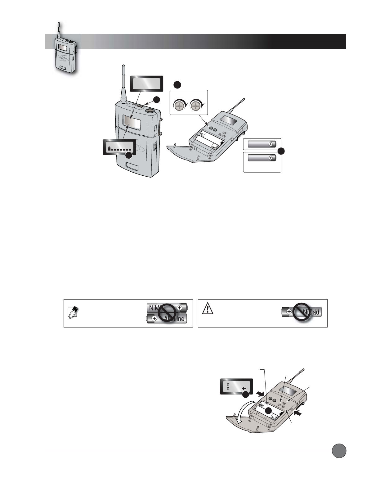
Operating Instructions
LightSPE
E
D
Wireless Transmitter
Belt-pack
CH: 001
720.250M
1
CH: 001
LightSPEED
3
1.1.
TT
ransmitter Mute: ransmitter Mute:
1.
T
ransmitter Mute: The MUTE switch turns the transmitter’s audio signal on or off. The audio is off when the red LED is
1.1.
TT
ransmitter Mute: ransmitter Mute:
flashing.
2.2.
Gain Adjust:Gain Adjust:
2.
Gain Adjust: When changing microphones or users, it may be necessary to adjust the transmitter gain based on differing
2.2.
Gain Adjust:Gain Adjust:
microphone sensitivities and voice levels.
• To adjust the microphone gain, turn the MT dial clockwise to increase the gain and counterclockwise to decrease the gain.
• If you are using a high impedence source, such as a guitar, it will be necessary to adjust the GT dial. Using a high
impedance source requires a special cable.
Gain Adjust
2
GT MT
GT
MT
Alkaline
4
NiMH
Nickel Metal Hydride
Rechargable
Contact LightSPEED Technologies for more information.
3.3.
BatterBatter
3.
3.3.
y Life Indicator: y Life Indicator:
Batter
y Life Indicator: The battery life is shown on the primary screen of the LCD. The 7-step fuel gauge acts as a
BatterBatter
y Life Indicator: y Life Indicator:
detailed guide to show the actual life of the battery.
4.4.
BatterBatter
y Ty T
4.
4.4.
Batter
BatterBatter
ype: ype:
y T
ype: The transmitter will operate with either standard Alkaline Batteries or Nickel Metal Hydride (NiMH)
y Ty T
ype: ype:
Rechargable Batteries. Since these types of batteries have different characteristics, it is important to set the transmitter to
the appropriate type of battery being used so that the battery life indicator will operate properly.
WARNING: Do not use NiCad
NOTE: Do not mix batter y types.
5.5.
TT
o Change the Battero Change the Batter
5.
T
o Change the Batter
5.5.
TT
o Change the Battero Change the Batter
y Ty T
ype Setting:ype Setting:
y T
ype Setting:
y Ty T
ype Setting:ype Setting:
batteries! They will not charge
properly and may cause damage
to the transmitter.
•Press the “UP” button twice to get to the battery type screen.
•Press and hold the “SET” button until a blinking cursor appears.
•Use the UP and DOWN buttons to make a selection.
•Press and hold the “SET” button again until the blinking
cursor disappears.
6.6.
Replacing the Batteries:Replacing the Batteries:
6.
Replacing the Batteries:
6.6.
Replacing the Batteries:Replacing the Batteries:
• Open the plastic door by depressing the latches on each side.
• Insert two AA batteries and snap the door closed.
Note the polarity in the battery compartment.
Typical battery life is about 8 hours.
Battery
Compartment
NiMH
AKLN
5
UP
Button
GT
MT
6
Door
Latch
DOWN
Button
Set
Button
LightSPEED Technologies • Wireless Sound Solutions • Toll Free: 1-800-840-3662
24
Page 27
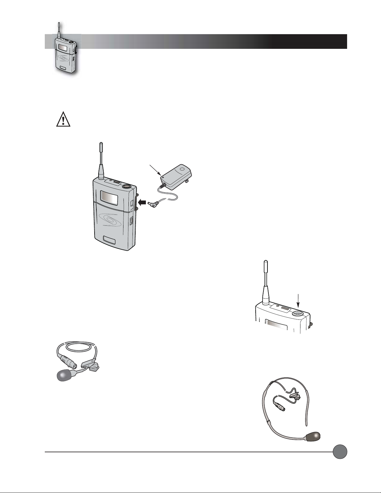
r
Operating Instructions
LightSPE
E
D
Charging the Batteries (NiMH Rechargeable Batteries ONLCharging the Batteries (NiMH Rechargeable Batteries ONL
Charging the Batteries (NiMH Rechargeable Batteries ONL
Charging the Batteries (NiMH Rechargeable Batteries ONLCharging the Batteries (NiMH Rechargeable Batteries ONL
Y):Y):
Y):
Y):Y):
Wireless Transmitter
Make sure there are NiMH Rechargeable Batteries in the transmitter before plugging in the charger .
WARNING: Do not attempt to charge alkaline batteries. They can
overheat and expand, creating a significant hazard and damaging
the transmitter.
(This is not covered by warranty.)
Charger Status LED
• RED = charging in progress
• GREEN = batteries fully
charged
•Switch the transmitter power off.
•Insert the small DC plug into the
jack on the side of the transmitter
labeled “CHG”.
•Plug the other end of the charger
into any standard 110 VAC outlet.
•The Red LED on the charger will
light indicating charge is in process.
•When the batteries are fully
LightSPEED
Charger
Connector
Transmitte
Charger
charged, the light on the charger
will turn green.
A full charge can
take up to 8 hours.
Belt-pack
CONNECTING THE MICROPHONECONNECTING THE MICROPHONE
CONNECTING THE MICROPHONE
CONNECTING THE MICROPHONECONNECTING THE MICROPHONE
LightSPEED offers various types of microphones that can be used with this system.
T o connect the microphone, simply insert the microphone connector into the TA4F
connector on top of the transmitter . To remove, press the black button on the
microphone connector and pull out.
MICROPHONE OPTIONSMICROPHONE OPTIONS
MICROPHONE OPTIONS
MICROPHONE OPTIONSMICROPHONE OPTIONS
The BP-900 T ransmitter can be used with either a lapel style microphone or a headset
microphone. Both plug into the top of the transmitter as shown.
Lapel MicrophoneLapel Microphone
Lapel Microphone
Lapel MicrophoneLapel Microphone
Several varieties of lapel microphones are available
(pictured is the Audio Technica 831).
connect the microphone cord directly into the jack on top of the transmitter and clip the microphone
to lapel or collar.
Several varieties of headset microphones are available
For optimal sound, position the microphone as close to the mouth as possible.
Headset MicrophoneHeadset Microphone
Headset Microphone
Headset MicrophoneHeadset Microphone
(pictured is the LightSPEED TK-250).
Simply connect the microphone cord directly into the jack on top of the transmitter and place
the headset around the back of the head.
For optimal sound, position the microphone just
beside the mouth.
Mic IN
Simply
LightSPEED Technologies • Wireless Sound Solutions • Toll Free: 1-800-840-3662
25
Page 28
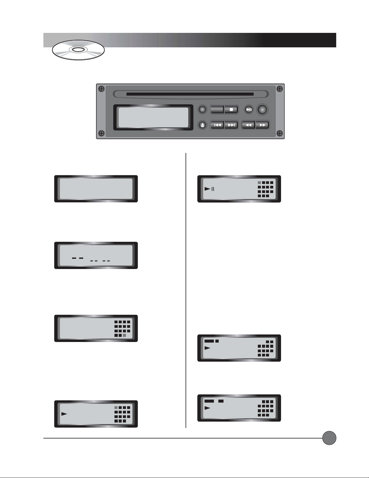
Operating Instructions
CD Player
NO
Playing a Compact DiscPlaying a Compact Disc
Playing a Compact Disc
Playing a Compact DiscPlaying a Compact Disc
When a CD is not loaded in the CD player , the LCD screen
will display the text ‘no disc’.
NO
T o play a disc, gently insert it into the CD slot. The CD
player will ‘grab’ the CD and load it automatically. While
the CD player ‘reads’ the track and time information, the
display shows dashes.
After a few seconds, the LCD screen will change to a
display showing the number of tracks, the total playing
time of the disc, and a grid showing up to 16 tracks that
will be played. The grid is very useful when programming
playlists.
diSC
diSC
STOP PLAY/PAUSEA — BREPEAT
T o stop playback, press the PLAY/PAUSE button once again
or press the STOP button. When paused, the PAUSE symbol
appears on the display.
01
00:12
Note: Use PAUSE instead of STOP to maintain the playback
position. Once STOP has been pressed, the playback will
resume at the beginning of the currently displayed track.
During playback, you can ‘fast forward’ or ‘rewind’ using the
SCAN/SEARCH buttons. You will see the time index move
quickly and hear ‘snippets’ of audio that you can use to listen
for the desired position.
T o remove the disc from the CD player, press the EJECT
button.
RepeatingRepeating
Repeating
RepeatingRepeating
The CD player can repeat the current track, the entire disc, or
an arbitrary section of the disc (called a ‘loop’).
PROG
SCAN/SEARCH— SKIP —EJECT
21 3 4
6 7 85
10 11 129
14 1513
21 3 4
6 7 85
10 11 129
15
77:52
Once the disc has been ‘read’ by the CD player , you can
either start playback from the first track on the disc, or use
the SKIP buttons to select a different track for playback.
T o start playback, press the PLAY/PAUSE button once. The
PLAY symbol appears on the
display.
01
00:06
LightSPEED Technologies • Wireless Sound Solutions • Toll Free: 1-800-840-3662
14 1513
21 3 4
6 7 85
10 11 129
14 1513
Press the REPEAT button once to repeat the current track.
REPEAT 1 will appear on the display.
REPEAT 1
02
03:45
Press the REPEAT button a second time to repeat the entire
disc.
REPEAT ALL will appear on the display.
REPEAT button a third time to cancel the repeat operation.
REPEAT ALL
02
04:31
6 7 85
10 11 129
14 1513
2 3 4
6 7 85
10 11 129
14 1513
3 4
Press the
26
Page 29
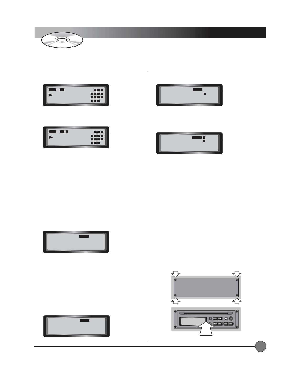
Operating Instructions
y
CD Player
... continued
T o create a loop, press the A->B button during playback at
the time index you have chosen as the beginning of the loop.
REPEAT A--->
01 00:32
Press the A->B button again when the time index reaches the
chosen end point of the loop.
REPEAT A---> B
01
During loop playback, you can use the PLAY/PAUSE button
and the SCAN/SEARCH buttons as normal. Press the A->B
button again to cancel the loop without affecting playback.
Press the STOP, SKIP, or EJECT buttons to cancel the loop
and perform the corresponding action.
Programming a PlaylistProgramming a Playlist
Programming a Playlist
Programming a PlaylistProgramming a Playlist
A playlist is a temporary, user programmable selection of
tracks that will play in the order that you select them. The
tracks selected will be shown in the grid on the right side of
the display.
Press the PROG button to start recording the track sequence.
The PROGRAM symbol appears on the display.
00:23
2 3 4
6 7 85
10 11 129
14 1513
2 3 4
6 7 85
10 11 129
14 1513
T o save the selection, press the PROG button again. The
track number will appear in the grid.
PROGRAM
5
01
P :02
Select another track for sequence number 02 and press the
PROG button again. The second track number will appear in
the grid.
1
PROGRAM
5
00
P :03
Once you have selected all of the tracks to be included in
your playlist, press the PLAY button to begin playback. Your
selections will be played in the order that you selected them.
While a playlist is playing, you can use many of the same
controls that are available during normal playback. PLAY/
PAUSE, SKIP, and SCAN/SEARCH all work as normal.
REPEAT also works as normal, repeating a single track or
repeating the entire playlist.
Once you reach the end of the playlist, the program will be
forgotten by the CD player unless you have REPEAT ALL
selected.
PROGRAM
00
P :01
The first set of digits on the display indicates the track
selection, and the second set of digits indicates the program
sequence number (starting at 01). When you select a track
for sequence number 01, the track number appears in the
first set of digits.
Note: The grid can only display the first 16 tracks on a disc.
If the disc has more than 16 tracks, you can still select them
during programming but you will not get visual confirmation
of the selection on the grid.
PROGRAM
05
P :01
LightSPEED Technologies • Wireless Sound Solutions • Toll Free: 1-800-840-3662
Installing a CD Player:Installing a CD Player:
Installing a CD Player:
Installing a CD Player:Installing a CD Player:
system is turned OFF.
filler panel using a small Phillips screwdriver. Locate the
header cable inside the control panel and connect it to the
CD player, observing proper polarity. Insert the CD player
into the control panel.
Install CD Pla
Make sure the power to the Delta X
Remove the four screws securing the
Replace the four screws.
Remove Four Screws
CD Filler Panel
PROG
PROG
STOP PLAY/PAUSEA — BREPEAT
CD-ROM ART GOES HERE
CD-ROM ART GOES HERE
NO
diSC
er and Replace Four Screws
STOP PLAY/PAUSEA — BREPEAT
SCAN/SEARCH— SKIP —EJECT
SCAN/SEARCH— SKIP —EJECT
27
Page 30

Trouble Shooting Guide
No sound when using any input (CD playerNo sound when using any input (CD player
No sound when using any input (CD player
No sound when using any input (CD playerNo sound when using any input (CD player
1. DELT A X main power should be turned ON.
on, the battery is most likely too weak and needs to be plugged into the charger.
2. Make sure the main power switch is set to ON and not MUTE.
3. Check the setting of the MASTER VOLUME control. This control sets the amount of audio coming out of the speakers. If it is
set to minimum, no sound will be produced.
No sound when someone speaks into the wireless microphone:No sound when someone speaks into the wireless microphone:
No sound when someone speaks into the wireless microphone:
No sound when someone speaks into the wireless microphone:No sound when someone speaks into the wireless microphone:
3. Microphone/transmitter power should be turned on.
Plug the microphone/transmitter into the charger (if the batteries are rechargeable) or replace with alkaline batteries.
NOTE: Do not attempt to charge alkaline batteries! This can result in severe damage to the transmitter that will
NOT be covered under warranty!
4. The transmitter and receiver should be set to the same channel
5. Verify that the receiver and transmitter are in the same frequency group.
• T urn the receiver off and then on again. The letter code for the frequency group will be shown briefly on the LED display.
• Open the battery compartment of the transmitter and find the frequency group sticker. The letter on the frequency group
sticker must match the letter code shown on the receiver display.
6. Make sure the red LED (on the belt-pack transmitter) is not flashing.
The wireless microphone is experiencing drop-out or interference:The wireless microphone is experiencing drop-out or interference:
The wireless microphone is experiencing drop-out or interference:
The wireless microphone is experiencing drop-out or interference:The wireless microphone is experiencing drop-out or interference:
, Line In, Wired Microphones, Wireless Microphones):, Line In, Wired Microphones, Wireless Microphones):
, Line In, Wired Microphones, Wireless Microphones):
, Line In, Wired Microphones, Wireless Microphones):, Line In, Wired Microphones, Wireless Microphones):
The green ON LED should be lit. If it does not light when the system is switched
If the LCD display does not show, the batteries are most likely too weak.
and the blue RF LED (A or B) on the receiver should be lit.
1. The wireless frequency being used may not be a clear channel.
receiver to find a clear frequency. Then make sure to select the same channel on the transmitter.
2. Squelch adjust on the receiver is set too high.
range of the transmitter , resulting in more frequent dropout.
3. Squelch adjust is set too low.
may be necessary to turn the squelch up slightly to avoid outside interference.
4. Transmitter is out of range of receiver.
environment. This range can be dramatically reduced indoors and when large objects (such as a wall) may be obstructing the
path directly between transmitter and receiver . If this is the case, it may be necessary to position the two closer together.
5. Batteries are very weak.
dramatically. Make sure to check the battery status of both the transmitter and DELTA X system.
LightSPEED Technologies • Wireless Sound Solutions • Toll Free: 1-800-840-3662
In areas of severe interference (large downtown urban areas, airports, military bases, etc) it
Just before the batteries are about to die, the overall performance of the system can degrade
If this squelch is set too high (fully clockwise), this can drastically reduce the
The transmitters do have a maximum range of about 300-350 feet in an open field
T urn the transmitter off and press the SCAN button on the
28
Page 31
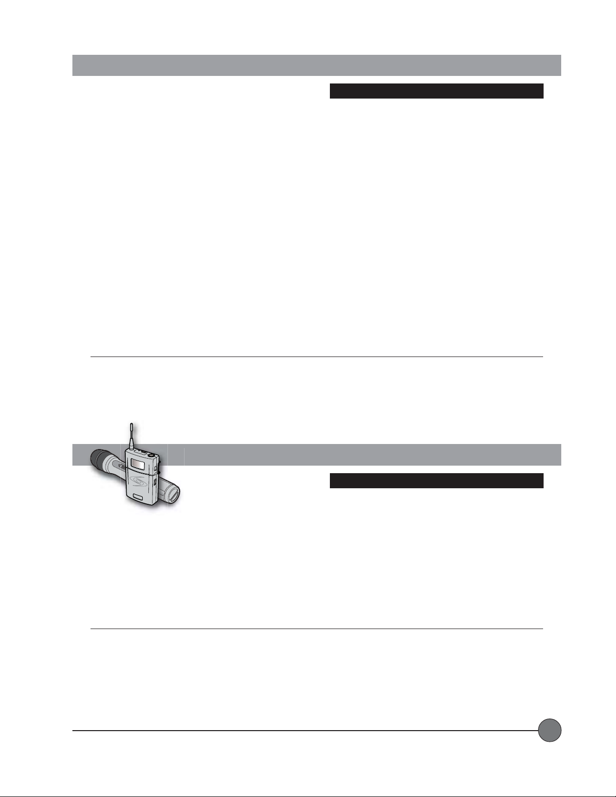
System Specifications
Delta X10/12 Base Unit
Nominal SPL (1W/1M)......................................... 97 dB ..................................................................................100 dB
Maximum SPL ...................................................... 116 dB ................................................................................ 120 dB
System Power (RMS) .......................................... 50 W at 8 W ........................................................................ 50 W at 8 W
Music Power......................................................... 65 W at 8 W........................................................................ 65 W at 8 W
Amplifier Type....................................................... Analog Class H .................................................................. Analog Class H
Frequency Response of amplifier ....................... 70 Hz – 20 k Hz .................................................................. 70 Hz – 2 0 k H z
Speaker System................................................... 2-Way with Passive Crossover.......................................... 2-Way with Passive Crossover
Woofer .................................................................. 10" 8 W............................................................................... 12" 8 W
Tweeter ................................................................. Foxtex FH15 ....................................................................... Foxt ex FH300
Internal Battery .................................................... 2 x 12V / 4.5AH ..................................................................2 x 12V / 7.2AH
Operating Time .................................................... 5-10 Hours ......................................................................... 7-12 Hours
Battery Charger ................................................... Internal 3-step Automatic Charger.................................... Internal 3-step Automatic Charger
AC Power ............................................................. 96 VAC – 240 VAC............................................................. 96 VAC – 24 0 VAC
Microphone Inputs ............................................... 2 XLR Jacks with Phantom Power.................................... 2 XLR Jacks with Phantom Power
Wireless Microphones ......................................... Up to t wo 100-Channel UHF True Diversity .....................Up to t wo 100-Channel UHF True Diversity
Line Input ............................................................. RCA ....................................................................................RCA
Line Output .......................................................... RCA ....................................................................................RCA
Tone Controls ....................................................... Individual Shelving Low-cut Filter for................................Individual Shelving Low-cut Filter for
Speaker Outputs .................................................. 1 Switched 8 Ohm / 1 Non-switched 8 Ohm .................... 1 Sw itched 8 Ohm / 1 Non-switched 8 Ohm
Dimensions (H x W x D inches) .......................... 23.25 x 13.25 x 11.25 ........................................................ 25.5 x 16 x 14.5
Weight (with battery)............................................ 41Lbs .................................................................................. 54Lbs
Note: Specifications are subject to change without notice.
DELTA X10 DELTA X12
Each Mic-input, Independent Bass and ...........................Each Mic-input, Independent Bass and
Treble Control for Music Sources......................................Treble Control for Music Sources
N
O
LightSPEED
RF Power Output .............................................................................................................................................................................................50 m W Maximum
Spurious Emission ............................................................................................................................................................................... >60 dB below the carrier
Macro Frequency Range............................................................................................................................................ 620 MHz to 745 MHz
Micro Frequency Range ................................................................................................................................................................... 25 Mhz each Macro-group
Tone-code Frequency............................................................................................................................................................................................... 32.768 KHz
Pre-emphasis ................................................................................................................................................................................................................... 50 µsec
Limiter Range....................................................................................................................................................................................... >30dB of audio overload
Battery T ype ..........................................................................................................................................................................................................................2 AA
Battery Life
BP Microphone Connector .................................................................................................................................................................................................. TA4F
BP Weight w/o Batteries.............................................................................................................................................................................................. 3 o z / 8 5g
HM Weight w/o Batteries........................................................................................................................................................................................ 4.2 oz / 120g
Note: Specifications are subject to change without notice.
LightSPEED Technologies • Wireless Sound Solutions • Toll Free: 1-800-840-3662
[Alkaline].........................................................................................................................................................................................
System Specifications
BP-900 and HM-900 Transmitters
[5 Macro-Groups]
Approx. 8 Hours
29
Page 32
Channel/Frequency Assignments
Wireless Channel Assignments
LightSPEED Frequency
Channel Range
E...................................................... 620.000 – 644.750
H ..................................................... 645.000 – 669.750
L ...................................................... 670.000 – 694.750
P...................................................... 695.000 – 719.750
U ..................................................... 720.000 – 744.750
Components & Accessories
Components & Accessories
Delta X10/12 Individual Components and Accessories
Order Code Product Description
AMP-DELTA-X10 Delta Series Amp w/10" Speaker
AMP-DELTA-X12 Delta Series Amp w/12" Speaker
RX-7100R 100 Channel UHF Receiver
TX-HM900 100 Channel UHF Handheld Transmitter
TX-BP900 100 Channel UHF Belt-pack Transmitter
AC-DELTACD CD Player for Delta X Systems
AC-SS1 Tripod Speaker Stand
AC-HCDELTA Hard Case for Delta X10 and X12
AC-SCDELTA Soft Side Trolley Case for Delta X10 and X12
MC-H10 Wired Dynamic Microphone
MC-831S Audio T echnica AT831 Lapel Mic
MC-TK250S LightSPEED Noise-canceling Headset Mic
MC-E6TS Countryman E6 Earset Mic - Tan Color
CA-AL50 50 Foot Active Link Cable
CA-AL100 100 Foot Active Link Cable
CA-ALGL Acive Link Ground Lift Cable
BA-LA12-5 12V/5AH Lead Acid Battery (Delta X10)
BA-LA12-7 12V/7AH Lead Acid Battery (Delta X12)
Contact your LightSPEED representative for details, pricing and availability.
For additional accessories, please visit our website.
LightSPEED Technologies • Wireless Sound Solutions • Toll Free: 1-800-840-3662
30
Page 33
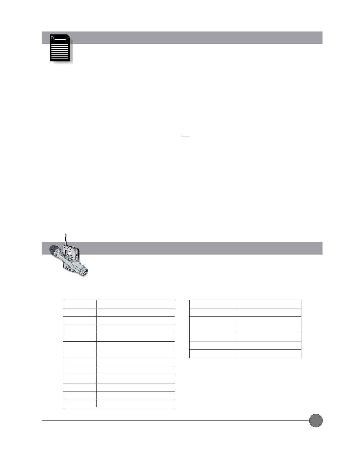
Warranty
The LightSPEED Technologies Delta X10 and Delta X12 are warranted to be free from defects in materials and workmanship for the period of SIX
(6) YEARS from the date of original purchase, subject to the following conditions:
1. The product must have been purchased from LightSPEED, an authorized LightSPEED Technologies Dealer, or
LightSPEED representative.
2. LightSPEED Technologies must perform all warranty service. Any service performed without the authorization of
LightSPEED Technologies will void the entire warranty.
3. This warranty does not cover any product that has been subjected to negligent use, connection to improper power
source, misuse, or operated beyond its manufactured specifications and limits, or has not been reasonably maintained.
4. Lead-Acid Batteries installed in the DELTA X Wireless Sound Systems shall be warranted for a TWO (2) YEAR period from date of purchase.
5. Rechargeable AA Nickel Metal Hydride
purchase.
6. Warranty shall not apply to batteries
power cords, bulbs, or any other failings due to normal wear.
7. Warranty is void when equipment is subjected to adverse temperature, humidity, moisture, or other conditions that are not considered
normal environmental conditions.
8. LightSPEED lapel, lavaliere, and headset microphones shall be warranted for ONE (1) year from date of purchase.
9. Third party microphones and accessories shall be under the original manufacturer’s warranty.
10. Warranty for wireless receivers and transmitters shall be three (3) years from date of purchase.
11. This warranty excludes all damages or defects caused by shipping, transporting, or inadequate packaging for
shipment.
12. Customers are responsible for freight charges to LightSPEED Technologies for service. LightSPEED Technologies will pay for return freight
to the end user by most reasonable method.
For warranty serFor warranty ser
For warranty ser
For warranty serFor warranty ser
to obtain Return Authorization approval and Rto obtain Return Authorization approval and R
to obtain Return Authorization approval and R
to obtain Return Authorization approval and Rto obtain Return Authorization approval and R
vice, please contact LightSPEED Tvice, please contact LightSPEED T
vice, please contact LightSPEED T
vice, please contact LightSPEED Tvice, please contact LightSPEED T
(NiMH)
batteries sold with some systems shall be warranted for ONE (1) YEAR from date of
(other than those mentioned in items 4 and 5 above)
echnologies customer serechnologies customer ser
echnologies customer ser
echnologies customer serechnologies customer ser
AA
A
(Return Authorization)
AA
vice department at (800.732.8999, 7:00AM – 5:00PM PST)vice department at (800.732.8999, 7:00AM – 5:00PM PST)
vice department at (800.732.8999, 7:00AM – 5:00PM PST)
vice department at (800.732.8999, 7:00AM – 5:00PM PST)vice department at (800.732.8999, 7:00AM – 5:00PM PST)
number number
..
number
.
number number
..
, exterior finish, AC
ON
Equipment Log
Record your system serial numbers and purchase information. This is helpful when ordering additional components,
accessories, and/or warranty service.
Component
Delta X10/X12
Receiver[s]
Serial Number
Purchase Information
Your Name/Company
Purchase Date
Dealer Name/Location
Transmitter[s]
Invoice #
Microphone[s]
LightSPEED Technologies • Wireless Sound Solutions • Toll Free: 1-800-840-3662
31
Page 34

User Notes
LightSPEED Technologies • Wireless Sound Solutions • Toll Free: 1-800-840-3662
32
Page 35

 Loading...