

LightSpeed Technologies FP 100 User Manual
LightSPEED
FP 100
Infrared Wireless Microphone System
User Manual
FP100 User Manual
FP 100 User Manual
CONGRATULATIONS!
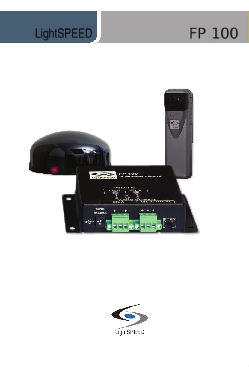
Congratulations on your purchase of the FP 100 Infrared Wireless
Microphone System! This simple, yet powerful technology adds the
benets of Classroom Audio to an existing amplier and speakers. This
system will seamlessly integrate into a sophisticated A/V control system.
With its small footprint, the FP 100 can mount in any discrete location—
whether it is an audio visual cabinet or below-ceiling tray.
The FP 100 is a compact, two-channel receiver that allows the use of up to
two wireless microphones simultaneously in the classroom. A standard IR
sensor provides high quality reception in rooms up to 1600 square feet. By
connecting additional infrared sensors to the receiver, the coverage area
can be expanded to provide optimal reception in varying room sizes and
congurations.
The LT-71 LightMic™ is a two-channel, rechargeable microphone that is
clipped to a lavaliere cord and worn around the neck for teacher use, or
it can be used as a standard handheld microphone for students to pass
around when speaking.
FP 100 User Manual | i

SAFETY INSTRUCTIONS
CAUTION
RISK OF ELECTRIC SHOCK DO NOT OPEN
CAUTION: TO REDUCE THE RISK OF ELECTRIC SHOCK
DO NOT REMOVE COVER (OR BACK)
NO USER-SERVICEABLE PARTS INSIDE
REFER SERVICING TO QUALIFIED PERSONNEL
The lightning ash with arrowhead symbol
within an equilateral triangle is intended to
alert the user to the presence of uninsulated
“dangerous voltage” within the product’s
enclosure, that may be sufcient magnitude to
constitute a risk of electric shock.
The exclamation point within an equilateral
triangle is intended to alert the user to
the presence of important operating and
maintenance (servicing) instructions in the
literature accompanying the appliance.
1.Read Instructions—All the safety
and operation instructions should
be read before this LightSPEED
product is operated.
2. Retain Instructions—The safety and
operating instructions should be
kept for future reference.
3.Heed Warning—All warnings
on this LightSPEED product and
in these instructions should
be followed.
FP 100 User Manual
FP 100 User Manual
7. Power Sources—This LightSPEED
product should be connected to a
power supply only of the type
described in these operation
instructions or as marked on this
LightSPEED product.
8. Power Cord Protection—Power supply
cords should be routed so that
they are not likely to be walked upon
or pinched by items placed upon or
against them.
9. Object and Liquid Entry—Care
should be taken so that objects do not
fall onto and liquids are not spilled into
the inside of this LightSPEED product.
0. Damage Requiring Service—This
1
LightSPEED product should be
serviced only by qualied service
personnel. The user should not
attempt to service this
LightSPEED product.
1. Prevent Electric Shock—do not use
1
this polarized plug with an extension
cord, receptacle or other outlet
unless the blades can be fully
inserted to prevent blade exposure.
4.Follow Instructions—All operating
and other instructions should
be followed.
5. Water and Moisture—This
LightSPEED product should not be
used near water.
6. Heat—This LightSPEED product
should be situated away from heat
sources such as radiators, etc.
ii | FP 100 User Manual

FP100 User Manual
FP 100 User Manual
TABLE OF CONTENTS
FP 100 INFRARED WIRELESS MICROPHONE SYSTEM
Safety Instructions ................................................................................................... ii
System Components ................................................................................................ 1
Controls and Connections ........................................................................................ 2
Front and Top Panel Controls ................................................................................ 2
Rear Panel Controls .................................................................................................. 3
LightMic Controls and Connections .......................................................................... 4
Optional Handheld Controls and Connections .......................................................... 5
System Installation .................................................................................................. 6
Unpacking Your System ........................................................................................ 6
Location of the Receiver ........................................................................................ 6
FP 100 Audio Connection ...................................................................................... 6
FP 100 Mixed Audio Connection ........................................................................... 8
IR Sensor Installation ............................................................................................... 9
Suspended Ceiling Mount ..................................................................................... 9
Wall/Solid Ceiling Mount ....................................................................................... 9
Finalizing Receiver Connections ............................................................................. 10
Final Check ......................................................................................................... 10
Initial Set-Up .......................................................................................................... 11
Initial Set-Up: Optional HM-70 Handheld Mic ......................................................... 12
Charging the LightMic ............................................................................................ 13
Charging the HM-70 Handheld Mic ......................................................................... 14
Troubleshooting Guide ............................................................................................ 15
Daily Use Instructions ............................................................................................. 16
Tips on Classroom Audio ........................................................................................ 17
Warranty Statement ............................................................................................... 17
System Specications ............................................................................................ 18
Individual Components and Optional Accessories .................................................. 19
User Notes ............................................................................................................. 20
FP 100 User Manual | iii

SYSTEM COMPONENTS
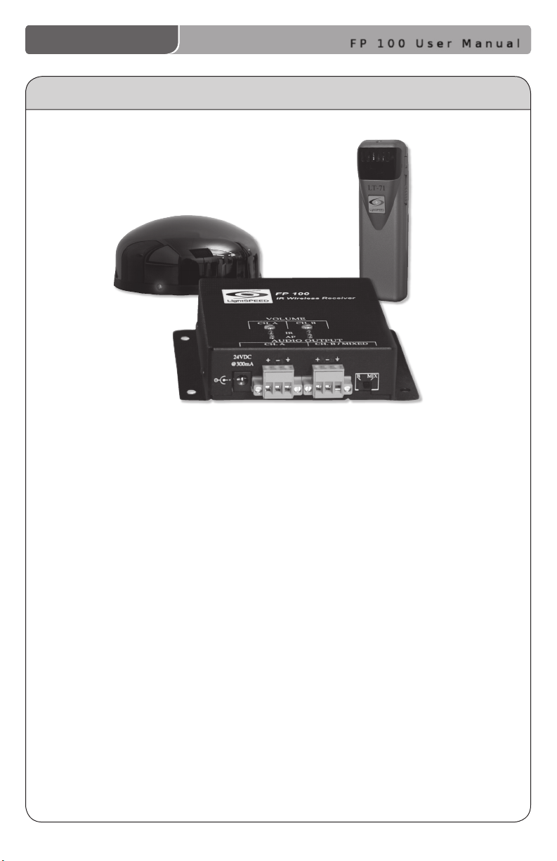
FP 100 Infrared Wireless Microphone System
SR-70F Infrared
Sensor
Power Supply
FP 100 User Manual
Sensor Cable
LT-71 LightMic™
Transmitter
Audio Patch Cable
Helpful
Hint
1 | FP 100 User Manual
Charger
Optional HM-70 Handheld Microphone
Keep ALL packaging materials. If the system must
be returned, using the original packing material
will be quick, convenient and prevent damage.
CONTROLS AND CONNECTIONS
FP100 User Manual
1
3
3
4
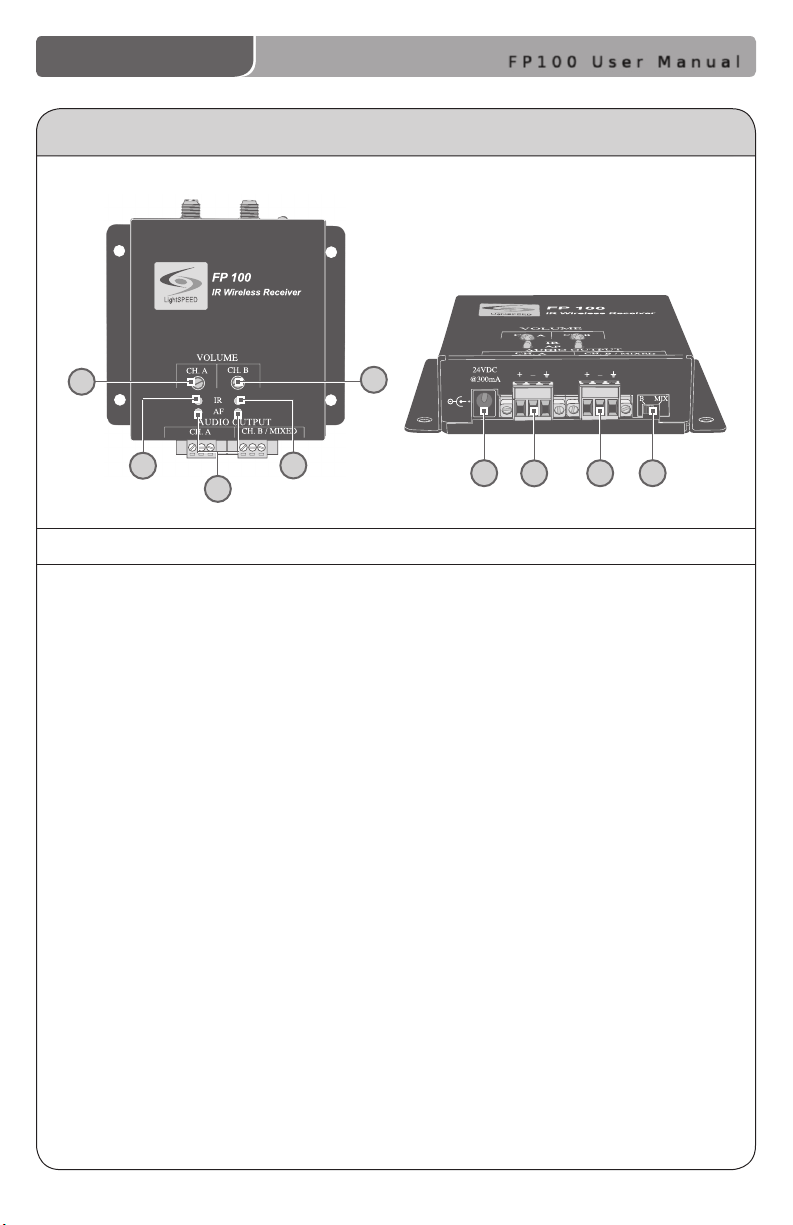
Front and Top Panel Controls
1. CH. A VOLUME: sets the nominal
volume level of the teacher
microphone (transmitter switched
to CH A). Rotating the adjustment
knob clockwise increases the
output level.
2. CH. B VOLUME: sets the nominal
volume level of the optional
second microphone (transmitter
switched to CH B). Rotating
the adjustment knob clockwise
increases the output level.
3. IR INDICATORS (IR): These lights
will glow red when the
corresponding transmitter is
turned on and being received.
This light conrms the FP 100 is
receiving a steady infrared signal.
4. AF INDICATORS (IR): These lights
ash green when audio (voice)
from the microphone is detected.
2
5
6
5. DC POWER INPUT: Plug the 24V
power supply into this jack.
6. CH. A AUDIO OUTPUT: This
balanced audio output can be
connected to a microphone or line
input on a mixer/amplier to
amplify the audio signal from the
CH. A transmitter.
7. CH. B / MIXED AUDIO OUTPUT:
This balanced audio output sends
the audio from the microphone set
to CH. B. Both CH. A and CH. B
transmitters (depending on the
position of the B/MIX switch) are
ouput to a microphone or line input
on a mixer/amplier.
8. B/MIX SWITCH: This switch
determines the audio source
that is output through the CH.B/
MIXED Audio Output jack. When
the switch is set to ‘MIX’ (default),
both the CH. A and CH. B signal are
output through this jack.
7
8
FP 100 User Manual | 2
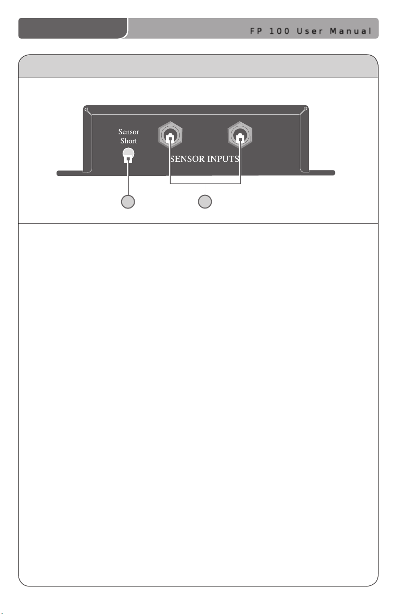
REAR PANEL CONTROLS
FP 100 User Manual
1
1. SENSOR SHORT: This LED glows
when there is a short in one of
the sensor cables.
2
2. SENSOR INPUT: The IR sensor
cable connects to the sensor input
jacks. Connect additional sensors to
the FP 100 to cover large or
odd-shaped rooms.
3 | FP 100 User Manual
FP100 User Manual
LT- 71
LT- 71
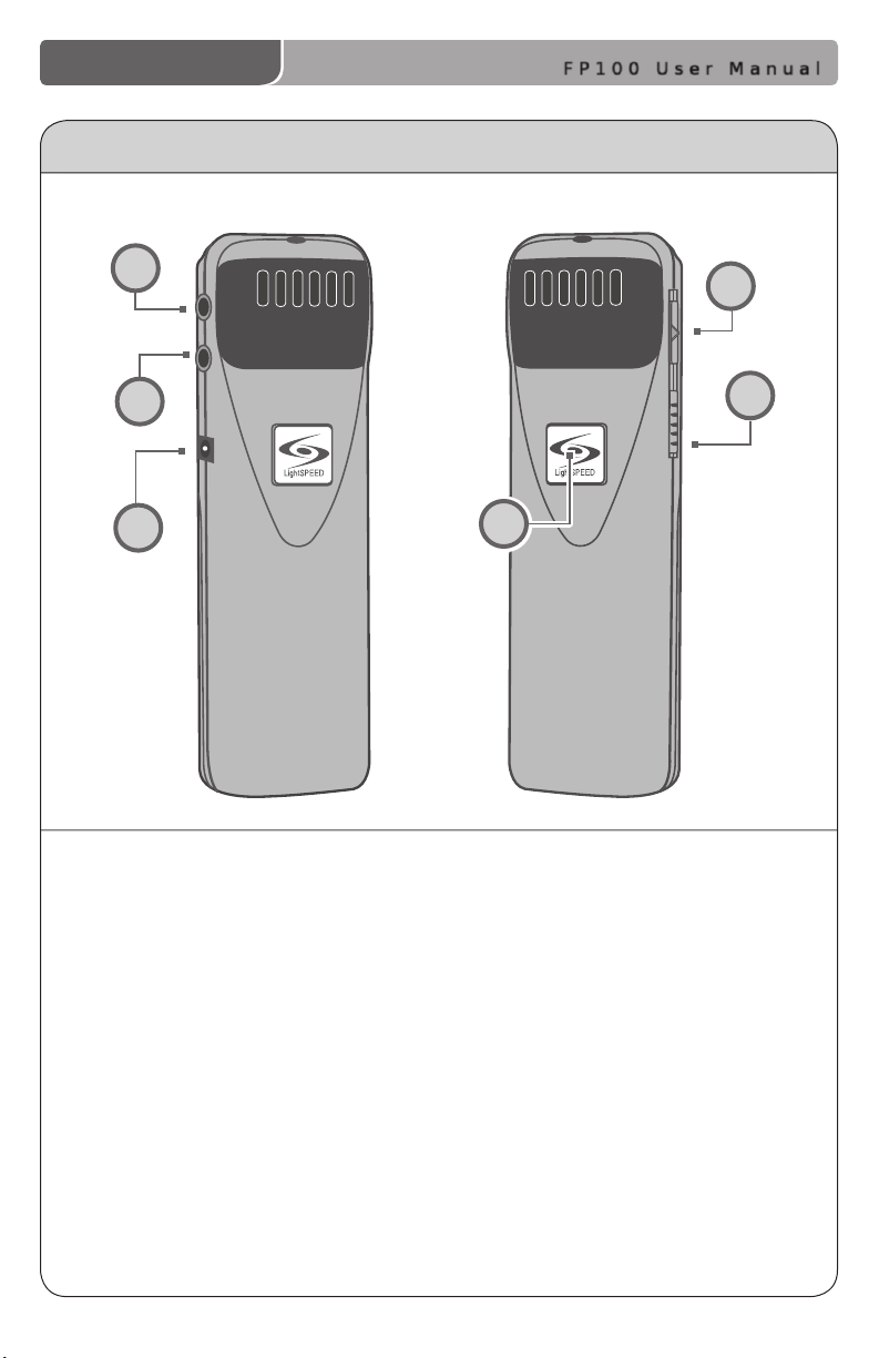
LIGHTMIC CONTROLS AND CONNECTIONS
4
5
6
1. ON/OFF/MUTE Switch: This switch,
located on the side of the LightMic,
turns the unit on or off/mute.
2. Channel Select Switch (CH A/B):
This switch allows for selection
between Channel A or B. If you are
using a single microphone/
transmitter for your system, we
recommend using Channel A.
3. Power/Charge LED Indicator: The
light glows blue when the LightMic
is powered ON, red when plugged
into the charging cable.
4. External Microphone Input (MIC):
Use the 3.5 mm MIC jack for the
optional TK-250 headset microphone
(part# MC-TK250LTM).
1
2
3
5. Auxiliary (AUX): Plug a laptop, MP3
player or other audio source into
this jack to wirelessly transmit the
audio signal to be played through
the FP 100.
6. Charger Input (CHARGER): Plug
the charging cable from the FP 100
into this jack for daily charging.
The LED on the front will glow red
to indicate charging.
FP 100 User Manual | 4
 Loading...