

LightSpeed Technologies Delta X12, Delta X10 User Manual
Table of Contents
System Overview .......................................................................................................................................................1
System Controls and Functions:
Base Unit...............................................................................................................................................................2
Wireless Receivers ................................................................................................................................................ 4
Wireless T ransmitter Wireless T ransmitter -
CD Player.............................................................................................................................................................. 7
System Installation:
Power/Charging .................................................................................................................................................... 8
Speaker Stand -
Speaker/System Placement .................................................................................................................................10
Operating Instructions:
Base Unit.............................................................................................................................................................11
Wireless Microphones.........................................................................................................................................12
Wired Microphones............................................................................................................................................. 13
CD Player............................................................................................................................................................ 14
Active Link ..........................................................................................................................................................15
External Speakers................................................................................................................................................16
External Audio IN/OUT ........................................................................................................................................ 17
Wireless Receivers .............................................................................................................................................. 18
Installing or Replacing a Receiver Module.......................................................................................................19
Wireless T ransmitter Wireless T ransmitter -
CD-Player ...........................................................................................................................................................26
T rouble Shooting Guide...........................................................................................................................................28
Specifications:
Base Unit/T ransmitters ........................................................................................................................................ 29
Channel/Frequency Assignments............................................................................................................................. 30
Components & Accessories.....................................................................................................................................30
Warranty Information/Equipment Log.......................................................................................................................31
User Notes...............................................................................................................................................................32
handheld microphone ........................................................................................................
belt-pack............................................................................................................................
tripod ..........................................................................................................................................
handheld microphone ......................................................................................................
belt-pack..........................................................................................................................
20
23
5
6
9
TM
LightSPEED
LightSPEED is a trademark of LightSPEED Technologies, Inc. Other names and brands
may be claimed as the property of others. Copyright © 2005 LightSPEED Technologies, Inc.,
All rights reserved. Printed in USA.
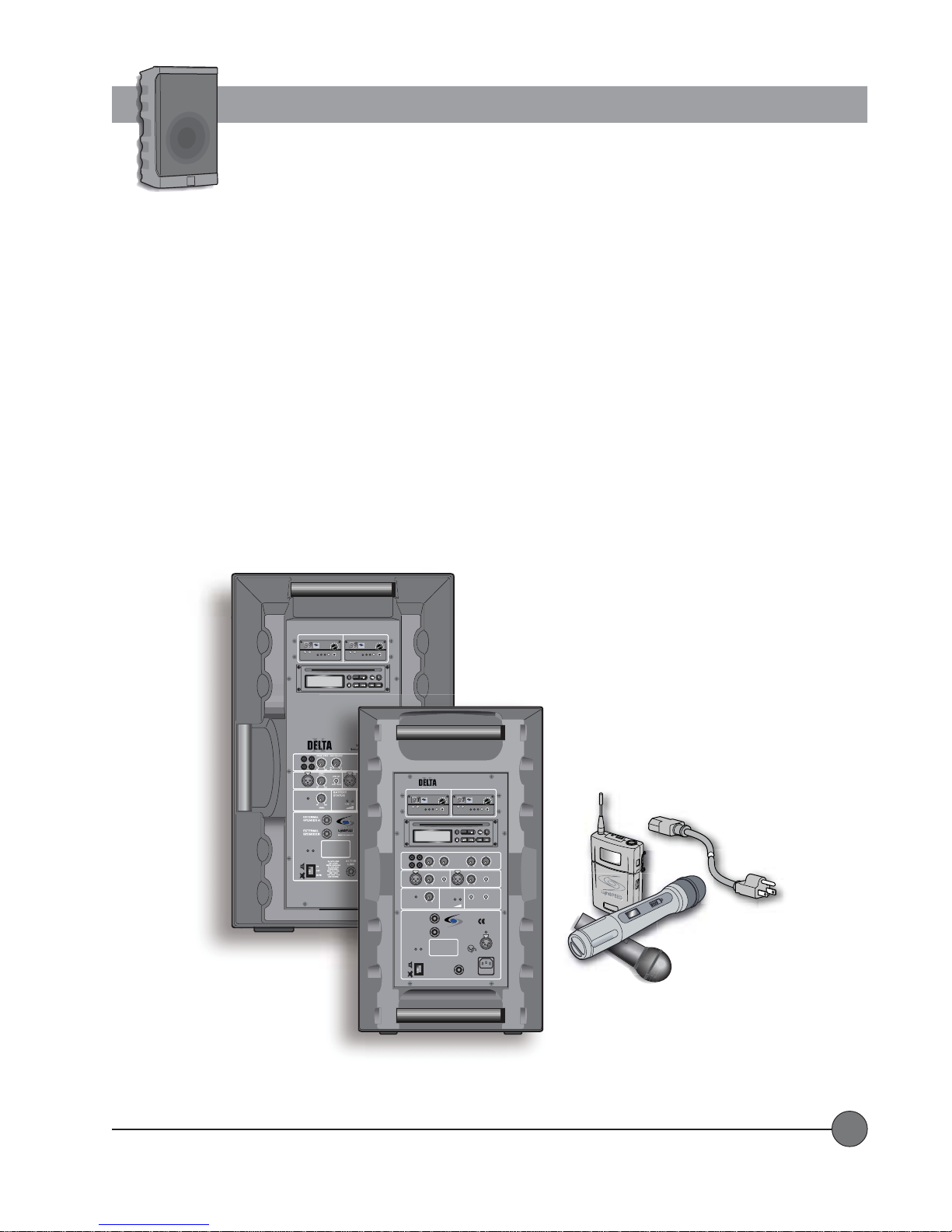
System Overview
The DEL TA X10 and X12 Wireless Sound Systems are powerful, rugged, and durable amplification systems designed for medium
to large-sized groups both indoors and out. The systems contain inputs for up to two UHF wireless microphone receivers,
optional integrated CD Player , two inputs for wired microphones, and an input for a line level audio source coming from a DVD
player , TV/VCR, Computer, etc. There is also a line output to connect to an external source such as a mixing console, an assistive
listening system or a recording device. Users can also connect to a passive speaker or a powered speaker in order to cover a
larger area. The systems operate on rechargeable battery power for up to 10 hours, and can also be plugged into AC power if
longer run-time is desired. An optional 12VDC cigarette lighter adaptor provides the ability to operate the systems using the
battery in your car in situations where there is no AC power available.
The wireless receivers contain 100 user-selectable frequencies ranging from 620 MHz to 745MHz. Each receiver contains a Clear
Channel Scan feature (a touch of a button automatically selects a clear frequency), low battery indicator (for the transmitter), and
adjustable squelch control. The systems are available with a variety of handheld, lapel, and headset microphones.
WIRELESS MIC 1 WIRELESS MIC 2
VOL
7100R
UHF TRUE
DIVERSITY
LightSPEED
RECEIVER
AB
CHANNEL
LOW
RF
SCAN SQ
BAT
NO
diSC
LINE
I
N
O
U
T
IN
MIC 1
MASTER
VOLUME
LIMIT
SWITCHED
8 OHM
8 OHM
ON MUTE
POWER
MaxPWR Min
7100R
UHF TRUE
DIVERSITY
LightSPEED
RECEIVER
AB
CHANNEL
LOW
RF
SCAN SQ
BAT
STOP PLAY/PAUSEA — BREPEAT
SCAN/SEARCH— SKIP —EJECT
Delta X12
VOL
MaxPWR Min
PROG
WIRELESS MIC 1 WIRELESS MIC 2
7100R
UHF TRUE
DIVERSITY
LightSPEED
RECEIVER
CHANNEL
LOW
BAT
NO
LINE/CD VOICE OVER MUSIC
LINE
I
N
O
U
T
min max dB dB
LEVEL
IN
MIC 1
min max
MASTER
VOLUME
LIMIT
min max
LEVEL
EXTERNAL
SPEAKER A
SWITCHED
8 OHM
EXTERNAL
SPEAKER B
8 OHM
ON MUTE
POWER
ON
OFF
MUTE
VOL
MaxPWR Min
AB
RF
SCAN SQ
CD-ROM ART GOES HERE
diSC
-40 0
LOW CUT
music speech
BATTERY
STATUS
LightSPEED
MADE IN EUROPE
DO NOT OPEN
THE COVER.
REFER SERVICING
TO QUALIFIED
PERSONNEL.
REPLACE FUSE
ONLY WITH
THE SAME TYPE
AND RATING.
Delta X10
Wireless
Sound System
VOL
7100R
UHF TRUE
DIVERSITY
LightSPEED
RECEIVER
MaxPWR Min
AB
CHANNEL
LOW
RF
SCAN SQ
BAT
PROG
STOP PLAY/PAUSEA — BREPEAT
SCAN/SEARCH— SKIP —EJECT
TONE CONTROLLEVEL
0
0
–+
–+
LOW
HIGH
LEVEL
IN
LOW CUT
music speech
min max
LOW CUT
LOW CUT
music speech
music speech
LOW OK
WIRELESS
WIRELESS
MIC 1
MIC 2
CHARGING STATUS
EXTERNAL
POWER
SOURCE
12VDC/4A
4
1
3
2
GND
+ 12V
MAINS
ACTIVE
AC
LINK
90-264V
47-63Hz
FUSE
T2A
MIC 2
ON
LightSPEED Technologies • Wireless Sound Solutions • Toll Free: 1-800-840-3662
1
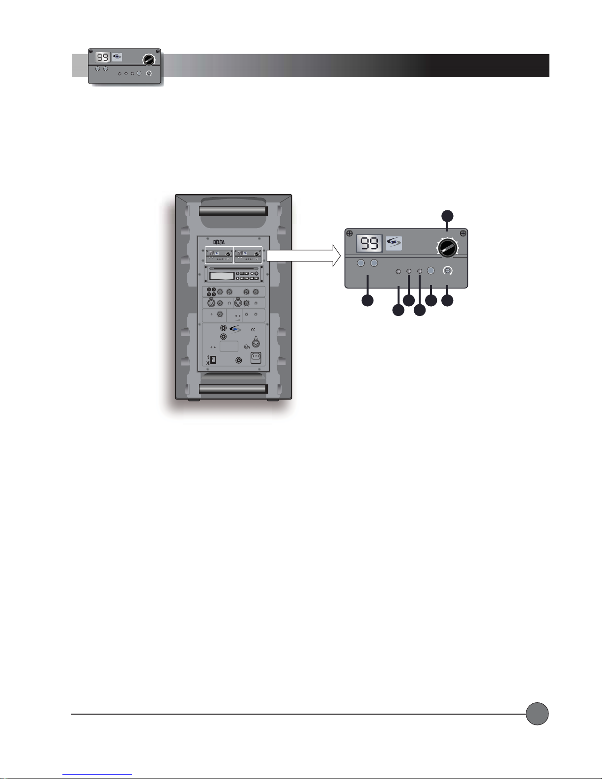
Controls and Functions
System Base Unit
WIRELESS MIC 1 WIRELESS MIC 2
VOL
7100R
UHF TRUE
DIVERSITY
LightSPEED
RECEIVER
AB
CHANNEL
LOW
RF
SCAN SQ
BAT
CD-ROM ART GOES HERE
NO
diSC
LINE
I
N
O
U
-40 0
T
min max dB dB
LEVEL
IN
LOW CUT
MIC 1
music speech
min max
MASTER
BATTERY
VOLUME
STATUS
LIMIT
min max
LEVEL
EXTERNAL
SPEAKER A
SWITCHED
8 OHM
EXTERNAL
SPEAKER B
8 OHM
ON MUTE
POWER
DO NOT OPEN
THE COVER.
REFER SERVICING
ON
TO QUALIFIED
PERSONNEL.
OFF
REPLACE FUSE
ONLY WITH
THE SAME TYPE
MUTE
AND RATING.
Delta X10
Wireless
Sound System
7100R
UHF TRUE
DIVERSITY
LightSPEED
RECEIVER
MaxPWR Min
AB
CHANNEL
LOW
RF
BAT
STOP PLAY/PAUSEA — BREPEAT
TONE CONTROLLEVELLINE/CD VOICE OVER MUSIC
0
–+
LOW
LEVEL
IN
min max
LOW CUT
music speech
LOW OK
WIRELESS
MIC 1
LightSPEED
MADE IN EUROPE
EXTERNAL
POWER
SOURCE
12VDC/4A
4
1
3
2
GND
+ 12V
MAINS
ACTIVE
AC
LINK
90-264V
47-63Hz
FUSE
T2A
SCAN SQ
SCAN/SEARCH— SKIP —EJECT
–+
LOW CUT
music speech
LOW CUT
music speech
WIRELESS
CHARGING STATUS
WIRELESS MIC 1 WIRELESS MIC 2
7100R
UHF TRUE
DIVERSITY
LightSPEED
RECEIVER
CHANNEL
AB
LOW
RF
SCAN SQ
BAT
1
VOL
MaxPWR Min
CHANNEL
LightSPEED
LOW
BAT
7100R
UHF TRUE
DIVERSITY
RECEIVER
AB
VOL
MaxPWR Min
RF
SCAN SQ
2
VOL
MaxPWR Min
PROG
0
HIGH
MIC 2
LINE
N
O
U
T
3
I
MIC 2
4
8 8
MIC 1
CD-ROM ART GOES HERE
NO
diSC
LINE/CD VOICE OVER MUSIC
-40 0
min max dB dB
5
LEVEL
IN
min max
LOW CUT
music speech
6
10 10
STOP PLAY/PAUSEA — BREPEAT
TONE CONTROLLEVEL
0
–+
LOW
LEVEL
IN
min max
PROG
SCAN/SEARCH— SKIP —EJECT
0
–+
HIGH
7
LOW CUT
music speech
MIC 2
9 9
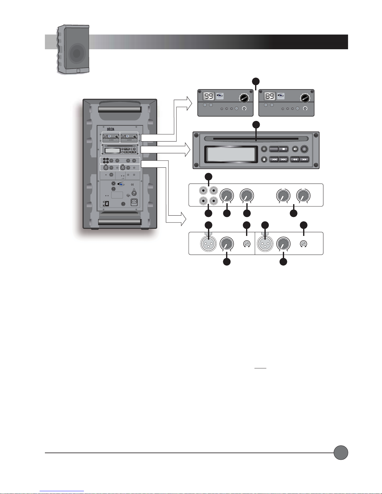
SYSTEM CONTROLS and FUNCTIONSSYSTEM CONTROLS and FUNCTIONS
SYSTEM CONTROLS and FUNCTIONS
SYSTEM CONTROLS and FUNCTIONSSYSTEM CONTROLS and FUNCTIONS
1.1.
WIRELESS MIC 1/WIRELESS MIC 2:WIRELESS MIC 1/WIRELESS MIC 2:
1.
WIRELESS MIC 1/WIRELESS MIC 2:
1.1.
WIRELESS MIC 1/WIRELESS MIC 2:WIRELESS MIC 1/WIRELESS MIC 2:
These may be wireless receivers or blank filler panels depending on your system
configuration.
2.2.
CD PLACD PLA
2.
2.2.
3.3.
3.
3.3.
4.4.
4.
4.4.
YER:YER:
CD PLA
YER:
CD PLACD PLA
YER:YER:
LINE IN:LINE IN:
LINE IN:
LINE IN:LINE IN:
LINE OUTLINE OUT
LINE OUT
LINE OUTLINE OUT
This may be a CD player or a blank filler panel depending on your system configuration.
RCA input jacks from an external audio device such as a TV, DVD, Computer, or MP3 player.
: :
:
RCA output jacks to send a line level audio signal to an external device such as a mixing console, recording
: :
device, or assistive listening transmitter .
5.5.
LINE/CD LEVEL:LINE/CD LEVEL:
5.
LINE/CD LEVEL:
5.5.
LINE/CD LEVEL:LINE/CD LEVEL:
6.6.
VOICE OVER MUSIC:VOICE OVER MUSIC:
6.
VOICE OVER MUSIC:
6.6.
VOICE OVER MUSIC:VOICE OVER MUSIC:
Controls the level of the Line In jacks and the CD player .
Automatically lowers the volume of the audio from the Line In jacks and the CD player when any
sounds are produced at the microphone inputs. T urn the VOICE OVER MUSIC control down for less Line In/CD signal when
microphones are in use.
7.7.
TONE CONTROL:TONE CONTROL:
7.
TONE CONTROL:
7.7.
TONE CONTROL:TONE CONTROL:
These control the levels of the LOW and HIGH frequencies (bass and treble) for the CD player and Line
In jacks. These controls DO NOT affect the microphone inputs.
8.8.
MIC 1 IN/MIC 2 IN:MIC 1 IN/MIC 2 IN:
8.
MIC 1 IN/MIC 2 IN:
8.8.
MIC 1 IN/MIC 2 IN:MIC 1 IN/MIC 2 IN:
These XLR connectors provide balanced inputs with phantom power for wired microphones or
external wireless systems.
9.9.
MIC 1 LEVEL/MIC 2 LEVEL:MIC 1 LEVEL/MIC 2 LEVEL:
9.
MIC 1 LEVEL/MIC 2 LEVEL:
9.9.
MIC 1 LEVEL/MIC 2 LEVEL:MIC 1 LEVEL/MIC 2 LEVEL:
10.10.
MIC 1 LOW CUT/MIC 2 LOW CUTMIC 1 LOW CUT/MIC 2 LOW CUT
10.
MIC 1 LOW CUT/MIC 2 LOW CUT
10.10.
MIC 1 LOW CUT/MIC 2 LOW CUTMIC 1 LOW CUT/MIC 2 LOW CUT
These control the levels of the wired microphone inputs.
::
:
These controls allow users to cut out the low frequency sound of the wired micro
::
phones, making the speech more intelligible.
LightSPEED Technologies • Wireless Sound Solutions • Toll Free: 1-800-840-3662
2

WIRELESS MIC 1 WIRELESS MIC 2
VOL
7100R
UHF TRUE
DIVERSITY
LightSPEED
RECEIVER
AB
CHANNEL
LOW
RF
SCAN SQ
BAT
CD-ROM ART GOES HERE
NO
diSC
LINE/CD VOICE OVER MUSIC
LINE
I
N
O
U
-40 0
T
min max dB dB
LEVEL
IN
LOW CUT
MIC 1
music speech
min max
MASTER
BATTERY
VOLUME
STATUS
LIMIT
min max
LEVEL
EXTERNAL
SPEAKER A
SWITCHED
8 OHM
EXTERNAL
SPEAKER B
8 OHM
ON MUTE
POWER
DO NOT OPEN
THE COVER.
REFER SERVICING
ON
TO QUALIFIED
PERSONNEL.
OFF
REPLACE FUSE
ONLY WITH
THE SAME TYPE
MUTE
AND RATING.
Delta X10
Wireless
Sound System
7100R
UHF TRUE
DIVERSITY
LightSPEED
RECEIVER
MaxPWR Min
AB
CHANNEL
LOW
RF
BAT
STOP PLAY/PAUSEA — BREPEAT
TONE CONTROLLEVEL
0
–+
LOW
LEVEL
IN
min max
LOW CUT
music speech
LOW OK
WIRELESS
MIC 1
LightSPEED
MADE IN EUROPE
EXTERNAL
POWER
SOURCE
12VDC/4A
4
1
3
2
GND
+ 12V
MAINS
ACTIVE
AC
LINK
90-264V
47-63Hz
FUSE
T2A
SCAN SQ
SCAN/SEARCH— SKIP —EJECT
–+
HIGH
LOW CUT
music speech
LOW CUT
music speech
WIRELESS
MIC 2
CHARGING STATUS
Controls and Functions
System Base Unit
... continued
12
11
MASTER
VOLUME
LIMIT
min max
LEVEL
VOL
MaxPWR Min
PROG
0
MIC 2
EXTERNAL
SPEAKER A
SWITCHED
8 OHM
EXTERNAL
SPEAKER B
8 OHM
ON MUTE
POWER
ON
OFF
MUTE
DO NOT OPEN
THE COVER.
REFER SERVICING
TO QUALIFIED
PERSONNEL.
REPLACE FUSE
ONLY WITH
THE SAME TYPE
AND RATING.
BATTERY
STATUS
LightSPEED
MADE IN EUROPE
13
LOW OK
ACTIVE
LINK
LOW CUT
music speech
WIRELESS
MIC 1
EXTERNAL
POWER
SOURCE
12VDC/ 4A
4
1
3
2
GND
+ 12V
MAINS
AC
90-264V
47-63Hz
FUSE
T2A
14
LOW CUT
music speech
WIRELESS
MIC 2
CHARGING STATUS
15
11.11.
LIMITLIMIT
11.
11.11.
12.12.
12.
12.12.
13.13.
13.
13.13.
14.14.
14.
14.14.
::
LIMIT
:
This LED lights up when the limiter is active, meaning that the power amplifiers are at maximum output.
LIMITLIMIT
::
MASTER VOLUME: MASTER VOLUME:
MASTER VOLUME:
MASTER VOLUME: MASTER VOLUME:
BABA
TTERTTER
Y STY ST
BA
TTER
Y ST
BABA
TTERTTER
Y STY ST
LOW CUT WIRELESS MIC 1/LOW CUT WIRELESS MIC 2:LOW CUT WIRELESS MIC 1/LOW CUT WIRELESS MIC 2:
LOW CUT WIRELESS MIC 1/LOW CUT WIRELESS MIC 2:
LOW CUT WIRELESS MIC 1/LOW CUT WIRELESS MIC 2:LOW CUT WIRELESS MIC 1/LOW CUT WIRELESS MIC 2:
Controls the overall volume level of the sound reaching the speaker(s).
AA
TUS:TUS:
A
TUS:
Indicates charge level of the internal batteries.
AA
TUS:TUS:
These controls allow users to cut out the low frequency
sound of the wireless microphones, making the speech more intelligible.
15.15.
POWER:POWER:
15.
15.15.
POWER:
POWER:POWER:
This switch turns the system ON and OFF. MUTE turns the system on while muting the internal and/or external
speaker(s).
16.16.
EXTERNAL SPEAKER B:EXTERNAL SPEAKER B:
16.
EXTERNAL SPEAKER B:
16.16.
EXTERNAL SPEAKER B:EXTERNAL SPEAKER B:
This ¼” phone connector provides a powered output for an external passive speaker
full sound to both the DEL TA X internal speaker and the external speaker).
17.17.
EXTERNAL SPEAKER A SWITCHED:EXTERNAL SPEAKER A SWITCHED:
17.
EXTERNAL SPEAKER A SWITCHED:
17.17.
EXTERNAL SPEAKER A SWITCHED:EXTERNAL SPEAKER A SWITCHED:
This ¼” phone connector provides a powered output for an external passive speaker
(mutes the DEL TA X internal speaker and provides full sound to the external speaker).
18.18.
ACTIVE LINK:ACTIVE LINK:
18.
ACTIVE LINK:
18.18.
ACTIVE LINK:ACTIVE LINK:
This balanced ¼” phone connector provides an audio link to another Delta X10 or Delta X12 system. When
connected properly, the sound from both Delta X systems is ‘shared’ between them.
the available inputs and sound level.
19.19.
MAINS:MAINS:
19.
MAINS:
19.19.
20.20.
20.
20.20.
This IEC connector is used for operating the system and charging the internal batteries from an AC source.
MAINS:MAINS:
EXTERNAL POWER SOURCE:EXTERNAL POWER SOURCE:
EXTERNAL POWER SOURCE:
EXTERNAL POWER SOURCE:EXTERNAL POWER SOURCE:
Provides a secondary power input for operation from 12VDC when the batteries are
discharged.
16 17
19
18
20
(provides
Using ACTIVE LINK, you can double
LightSPEED Technologies • Wireless Sound Solutions • Toll Free: 1-800-840-3662
3
CHANNEL
VOL
7100R
UHF TRUE
DIVERSITY
LightSPEED
RECEIVER
LOW
BAT
AB
RF
SCAN SQ
MaxPWR Min
Controls and Functions
Wireless Receiver(s)
Delta X10
WIRELESS MIC 1 WIRELESS MIC 2
7100R
UHF TRUE
DIVERSITY
LightSPEED
RECEIVER
AB
CHANNEL
LOW
RF
SCAN SQ
BAT
CD-ROM ART GOES HERE
NO
diSC
LINE/CD VOICE OVER MUSIC
LINE
I
N
O
U
-40 0
T
min max dB dB
LEVEL
IN
MIC 1
min max
MASTER
VOLUME
LIMIT
min max
LEVEL
EXTERNAL
SPEAKER A
SWITCHED
8 OHM
EXTERNAL
SPEAKER B
8 OHM
ON MUTE
POWER
DO NOT OPEN
THE COVER.
REFER SERVICING
ON
TO QUALIFIED
PERSONNEL.
OFF
REPLACE FUSE
ONLY WITH
THE SAME TYPE
MUTE
AND RATING.
7100R WIRELESS RECEIVER CONTROLS and FUNCTIONS7100R WIRELESS RECEIVER CONTROLS and FUNCTIONS
7100R WIRELESS RECEIVER CONTROLS and FUNCTIONS
7100R WIRELESS RECEIVER CONTROLS and FUNCTIONS7100R WIRELESS RECEIVER CONTROLS and FUNCTIONS
1.1.
Wireless Receiver Power/VWireless Receiver Power/V
1.
Wireless Receiver Power/V
1.1.
Wireless Receiver Power/VWireless Receiver Power/V
olume Adjustment:olume Adjustment:
olume Adjustment:
olume Adjustment:olume Adjustment:
music speech
VOL
LOW CUT
BATTERY
STATUS
MaxPWR Min
LightSPEED
MADE IN EUROPE
VOL
7100R
UHF TRUE
DIVERSITY
LightSPEED
RECEIVER
MaxPWR Min
AB
CHANNEL
LOW
RF
SCAN SQ
BAT
PROG
STOP PLAY/PAUSEA — BREPEAT
SCAN/SEARCH— SKIP —EJECT
TONE CONTROLLEVEL
0
0
–+
–+
LOW
HIGH
LEVEL
IN
LOW CUT
MIC 2
music speech
min max
LOW CUT
LOW CUT
music speech
music speech
LOW OK
WIRELESS
WIRELESS
MIC 1
MIC 2
CHARGING STATUS
EXTERNAL
POWER
SOURCE
12VDC/4A
4
1
3
2
GND
+ 12V
MAINS
ACTIVE
AC
LINK
90-264V
47-63Hz
FUSE
T2A
Turn this knob clockwise to power up the receiver. Rotate to adjust the
Wireless
Sound System
audio output level.
100-channel UHF Receiver Module
7100R
UHF TRUE
DIVERSITY
LightSPEED
RECEIVER
CHANNEL
2
LOW
BAT
3
AB
RF
4
SCAN SQ
6
5
1
VOL
MaxPWR Min
7
2.2.
Channel Control:Channel Control:
2.
Channel Control:
2.2.
Channel Control:Channel Control:
3.3.
TT
ransmitter Low Batterransmitter Low Batter
3.
T
ransmitter Low Batter
3.3.
TT
ransmitter Low Batterransmitter Low Batter
Manually select the desired channel (00-99) by pressing these two buttons.
y Indicator:y Indicator:
y Indicator:
y Indicator:y Indicator:
that is set to the same channel.
4.4.
RF Channel "A" Indicator:RF Channel "A" Indicator:
4.
RF Channel "A" Indicator:
4.4.
RF Channel "A" Indicator:RF Channel "A" Indicator:
5.5.
RF Channel "B" Indicator:RF Channel "B" Indicator:
5.
RF Channel "B" Indicator:
5.5.
RF Channel "B" Indicator:RF Channel "B" Indicator:
6.6.
Scan Button:Scan Button:
6.
Scan Button:
6.6.
Scan Button:Scan Button:
7.7.
Squelch Adjustment:Squelch Adjustment:
7.
Squelch Adjustment:
7.7.
Squelch Adjustment:Squelch Adjustment:
Press this button to automatically select a channel that is free from interference.
LightSPEED Technologies • Wireless Sound Solutions • Toll Free: 1-800-840-3662
The "A" LED lights up indicating the "A" channel tuner is receiving the strongest RF signal.
The "B" LED lights up indicating the "B" channel tuner is receiving the strongest RF signal.
Adjusts the squelch level for elimination of RF interference.
This LED lights to indicate a low battery level in the transmitter
(handheld or belt-pack)
4

N
O
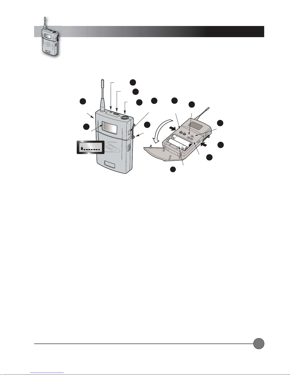
Controls and Functions
Wireless Transmitter
Handheld Microphone
LOCK
4
1
DOWN
2
ON
3
CH: 002
LCD Display
HM-900 HANDHELD MICROPHONE CONTROLS and FUNCTIONSHM-900 HANDHELD MICROPHONE CONTROLS and FUNCTIONS
HM-900 HANDHELD MICROPHONE CONTROLS and FUNCTIONS
HM-900 HANDHELD MICROPHONE CONTROLS and FUNCTIONSHM-900 HANDHELD MICROPHONE CONTROLS and FUNCTIONS
1.1.
Power Switch:Power Switch:
1.
Power Switch:
1.1.
Power Switch:Power Switch:
2.2.
LCD Display:LCD Display:
2.
LCD Display:
2.2.
LCD Display:LCD Display:
3.3.
Red LED:Red LED:
3.
Red LED:
3.3.
Red LED:Red LED:
Turns the transmitter ON.
Information screen appears when the power is switched on.
Lights up briefly when power is switched on.
8
Battery
Compartment
6
End View of Microphone
LOCK SET
HM-900
SET
5
UP
6
7
4.4.
Lock Button:Lock Button:
4.
Lock Button:
4.4.
Lock Button:Lock Button:
5.5.
Set Button:Set Button:
5.
Set Button:
5.5.
Set Button:Set Button:
6.6.
Up and Down Buttons:Up and Down Buttons:
6.
Up and Down Buttons:
6.6.
Up and Down Buttons:Up and Down Buttons:
Locks all microphone controls.
This button is used to enter and save changes to the transmitter settings.
These buttons scroll up and down between setup screens on the LCD display. They are also used
to enter changes in each setup screen.
7.7.
BatterBatter
7.
7.7.
8.8.
8.
8.8.
LightSPEED Technologies • Wireless Sound Solutions • Toll Free: 1-800-840-3662
y Charge Jack:y Charge Jack:
Batter
y Charge Jack:
BatterBatter
y Charge Jack:y Charge Jack:
BatterBatter
y Compartment:y Compartment:
Batter
y Compartment:
BatterBatter
y Compartment:y Compartment:
Optional battery charger plugs in here
Bottom section of microphone barrel unscrews to reveal batterycompartment.
(for NiMH batteries only).
5
Controls and Functions
LightSPEED
1
On/Off
Switch
Display
2
LCD
CH: 001
LightSPEED
Red LED
Mute
Switch
3
Mic
Jack
Wireless Transmitter
Belt-pack
4
5
6
Battery
Charge
Jack
7
Belt
Clip
8
Gain
Adjust
Battery
12
Compartment
9
UP
10
Door
Latch
9
Set
11
GT
MT
DOWN
BP-900 BELBP-900 BEL
BP-900 BEL
BP-900 BELBP-900 BEL
1.1.
Power Button:Power Button:
1.
Power Button:
1.1.
Power Button:Power Button:
2.2.
LCD Display:LCD Display:
2.
LCD Display:
2.2.
LCD Display:LCD Display:
3.3.
Red LED:Red LED:
3.
Red LED:
3.3.
Red LED:Red LED:
4.4.
Mute Switch:Mute Switch:
4.
Mute Switch:
4.4.
Mute Switch:Mute Switch:
5.5.
Microphone Jack:Microphone Jack:
5.
Microphone Jack:
5.5.
Microphone Jack:Microphone Jack:
6.6.
BatterBatter
6.
Batter
6.6.
BatterBatter
7.7.
Belt ClipBelt Clip
7.
Belt Clip
7.7.
Belt ClipBelt Clip
8.8.
Gain:Gain:
8.
Gain:
8.8.
Gain:Gain:
9.9.
UP and Down Buttons:UP and Down Buttons:
9.
UP and Down Buttons:
9.9.
UP and Down Buttons:UP and Down Buttons:
to enter changes in each setup screen.
10.10.
Set Button:Set Button:
10.
Set Button:
10.10.
Set Button:Set Button:
11.11.
Door Latch:Door Latch:
11.
Door Latch:
11.11.
Door Latch:Door Latch:
12.12.
BatterBatter
12.
Batter
12.12.
BatterBatter
TT
-P-P
ACK TRANSMITTER CONTROLS and FUNCTIONSACK TRANSMITTER CONTROLS and FUNCTIONS
T
-P
ACK TRANSMITTER CONTROLS and FUNCTIONS
TT
-P-P
ACK TRANSMITTER CONTROLS and FUNCTIONSACK TRANSMITTER CONTROLS and FUNCTIONS
T urns the transmitter ON.
Information screen appears when the power is switched on.
Lights up briefly when power is switched on, flashes continuously when audio signal is muted.
Turns the audio signal on or off.
Microphone connects to transmitter here.
y Charge Jack: y Charge Jack:
y Charge Jack:
y Charge Jack: y Charge Jack:
Provides adjustment for differing voice levels and microphone sensitivities.
This button is used to enter and save changes to the transmitter settings.
A door latch button is located on each side. Press both to open the battery compartment door.
y Compartmenty Compartment
y Compartment
y Compartmenty Compartment
Optional battery charger plugs in here
These buttons scroll up and down between setup screens on the LCD display. They are also used
(Hold for two seconds.)
The red LED will flash when MUTE is engaged.
(for NiMH batteries only).
LightSPEED Technologies • Wireless Sound Solutions • Toll Free: 1-800-840-3662
6
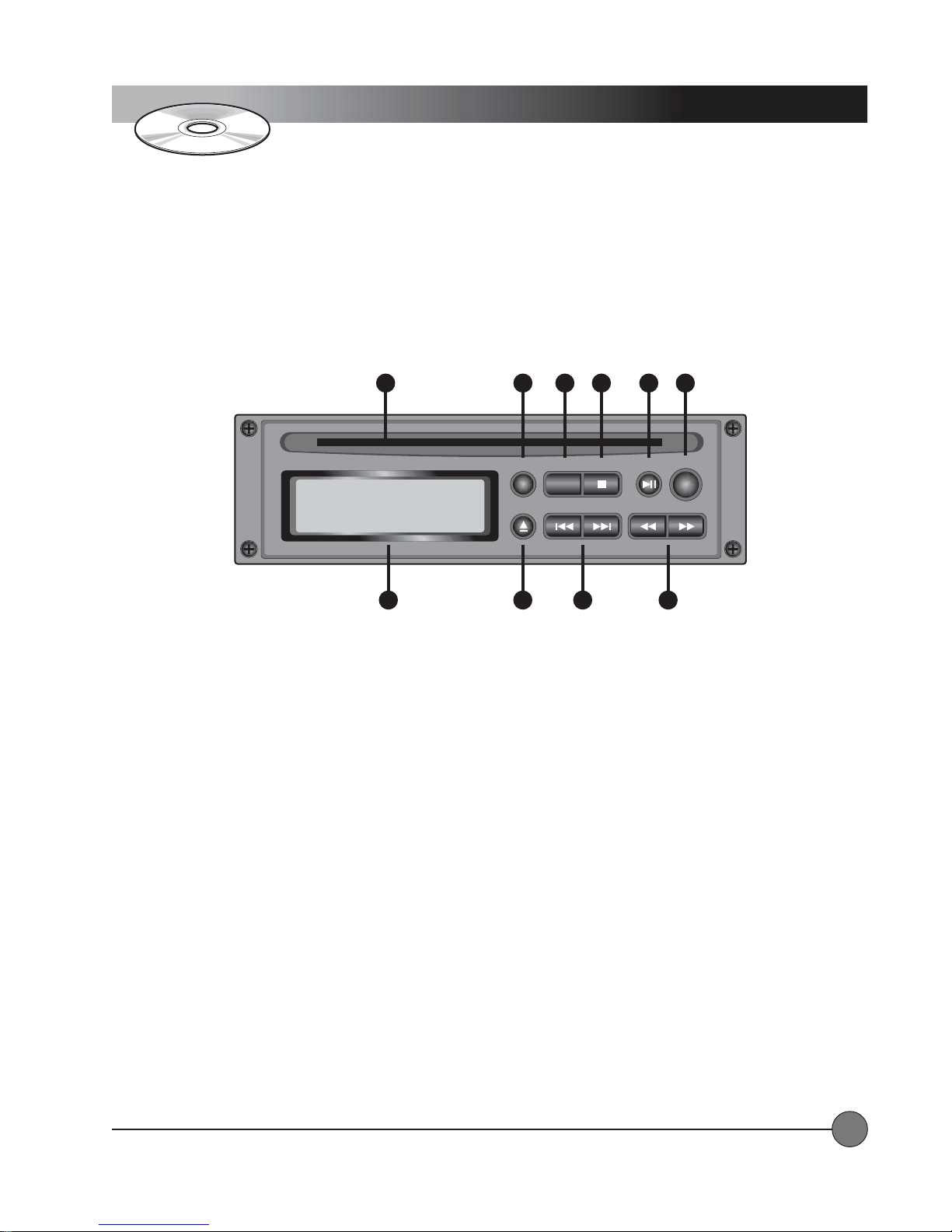
Controls and Functions
CD Player
CD PLACD PLA
CD PLA
CD PLACD PLA
1.1.
CD Slot:CD Slot:
1.
CD Slot:
1.1.
CD Slot:CD Slot:
2.2.
REPEAREPEA
2.
REPEA
2.2.
REPEAREPEA
3.3.
AA
3.
A
3.3.
AA
4.4.
STOP Button:STOP Button:
4.
STOP Button:
4.4.
STOP Button:STOP Button:
1
NO diSC
CD Player Front Panel
7
YER CONTROLS and FUNCTIONSYER CONTROLS and FUNCTIONS
YER CONTROLS and FUNCTIONS
YER CONTROLS and FUNCTIONSYER CONTROLS and FUNCTIONS
Insert CD here.
T Button:T Button:
T Button:
T Button:T Button:
--
B Button:B Button:
-
B Button:
--
B Button:B Button:
Press once to repeat a track, press twice to repeat an entire disc or playlist.
Sets start and end points for a playback loop.
Stops playback.
2
3
4 5
STOP PLAY/PAUSEA — BREPEAT
8
9
6
PROG
SCAN/SEARCH— SKIP —EJECT
10
5.5.
PLAPLA
Y/PY/P
5.
5.5.
6.6.
6.
6.6.
7.7.
7.
7.7.
8.8.
8.
8.8.
9.9.
9.
9.9.
10.10.
10.
10.10.
LightSPEED Technologies • Wireless Sound Solutions • Toll Free: 1-800-840-3662
AUSE Button:AUSE Button:
PLA
Y/P
AUSE Button:
PLAPLA
Y/PY/P
AUSE Button:AUSE Button:
PROG Button:PROG Button:
PROG Button:
PROG Button:PROG Button:
LCD Display:LCD Display:
LCD Display:
LCD Display:LCD Display:
EJECT Button:EJECT Button:
EJECT Button:
EJECT Button:EJECT Button:
SKIP Buttons:SKIP Buttons:
SKIP Buttons:
SKIP Buttons:SKIP Buttons:
SCAN/SEARCH Buttons:SCAN/SEARCH Buttons:
SCAN/SEARCH Buttons:
SCAN/SEARCH Buttons:SCAN/SEARCH Buttons:
playing ‘snippets’ to allow searching.
Starts playback or pauses playback.
Used to create playlists.
Shows information about the disc and current mode of operation.
Ejects the disc.
Skips to the beginning of the next or previous track.
Similar to fast forward and rewind. Moves quickly forward or backward through the disc while
7
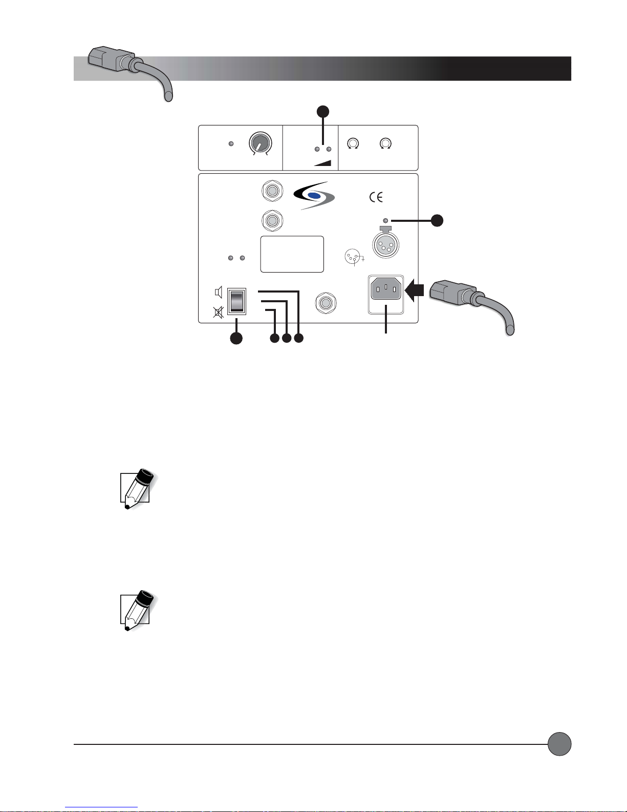
System Installation
2
Power/Charging
MASTER
VOLUME
LIMIT
min max
LEVEL
EXTERNAL
SPEAKER A
SWITCHED
8 OHM
EXTERNAL
SPEAKER B
8 OHM
ON MUTE
POWER
ON
OFF
MUTE
3
CHARGING THE BACHARGING THE BA
CHARGING THE BA
CHARGING THE BACHARGING THE BA
TTERTTER
TTER
TTERTTER
YY
Y
YY
After unpacking the unit for the first time, please charge the batteries for at least 10 hours before operation. The battery charger
is built in as an integral part of the system. T o charge the batteries, plug one end of the IEC power cable into the MAINS
connector and plug the other end into an AC outlet (90-264VAC, 47-63Hz).
1. CHARGING STATUS LED: The Charging Status LED will light up when external power is supplied. The color of the LED
indicates the charging status as follows:
REDRED
•
RED means fast-charge mode.
REDRED
ORANGEORANGE
•
ORANGE means trickle-charge mode.
ORANGEORANGE
GREENGREEN
•
GREEN means no charging.
GREENGREEN
The batteries are very low or completely discharged.
The batteries are fully charged.
BATTERY
STATUS
DO NOT OPEN
THE COVER.
REFER SERVICING
TO QUALIFIED
PERSONNEL.
REPLACE FUSE
ONLY WITH
THE SAME TYPE
AND RATING.
B
C
LOW OK
LightSPEED
MADE IN EUROPE
A
ACTIVE
LINK
LOW CUT
music speech
WIRELESS
MIC 1
EXTERNAL
POWER
SOURCE
12VDC/ 4A
4
1
3
2
GND
+ 12V
MAINS
AC
90-264V
47-63Hz
FUSE
T2A
LOW CUT
music speech
WIRELESS
MIC 2
CHARGING STATUS
AC Power IN
The batteries are not yet fully charged.
1
IEC Power
Cable
NOTE: If the batteries are low and there is an AC outlet available, you can connect the AC
mains and operate the system as normal while the batteries are charging. However , to fully
charge the system, it should be switched OFF until the CHARGING STATUS LED turns green.
DETERMINING BADETERMINING BA
DETERMINING BA
DETERMINING BADETERMINING BA
TTERTTER
TTER
TTERTTER
Y STY ST
Y ST
Y STY ST
AA
A
AA
TUSTUS
TUS
TUSTUS
2. BA TTER Y STATUS LEDs: The Battery Status LEDs indicate the amount of charge available even when the AC mains are
disconnected. Whenever the batteries have enough charge to operate the system, the green OK LED will light. As the
batteries discharge, the red LOW LED will begin to glow, and the green OK LED will stay lit. When the red LOW LED is
glowing brightly, the battery is very low. Once the batteries discharge to an unusable level, the system will shut off and you
will need to connect to an external power source.
NOTE: It is possible to operate the system from a 12VDC external source when the batteries
are fully discharged and no AC power source is available. A special adaptor cable allows
connection directly to a car cigarette lighter . Contact LightSPEED for more information.
SYSTEM POWERSYSTEM POWER
SYSTEM POWER
SYSTEM POWERSYSTEM POWER
3. The POWER switch has three positions as follows:
A.A.
ONON
A.
ON Position: The green ON LED will light and the power amps will be active. This is the normal mode of operation
A.A.
ONON
with the internal and external speakers producing sound.
B.B.
OFFOFF
B.
OFF Position: No LEDs will light and the system is off.
B.B.
OFFOFF
C.C.
MUTEMUTE
C.
MUTE Position: The green ON LED and the amber MUTE LED will light and the power amps will be disabled. This is
C.C.
MUTEMUTE
a special mode of operation in which all of the controls and functions work as normal, but no sound is produced by
the internal or external speakers.
LightSPEED Technologies • Wireless Sound Solutions • Toll Free: 1-800-840-3662
8
System Installation
Speaker Stand(tripod)
1
Locking
Knob
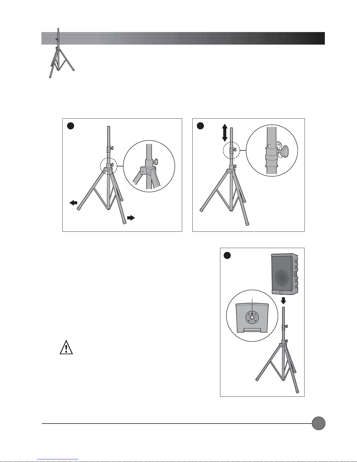
SPEAKER STSPEAKER ST
SPEAKER ST
SPEAKER STSPEAKER ST
1.1.
Extending the Legs: Extending the Legs:
1.
Extending the Legs: Loosen the lower knob and pull outward on two
1.1.
Extending the Legs: Extending the Legs:
legs of the tripod. Extend the legs until the center post is just above the
floor . The center post should NOT touch the floor.
AND (TRIPOD)AND (TRIPOD)
AND (TRIPOD)
AND (TRIPOD)AND (TRIPOD)
Tighten the lower
knob.
2
Safety
Pin
Locking
Knob
3
2.2.
Extending the Center Post:Extending the Center Post:
2.
Extending the Center Post: Loosen the upper knob and pull the center
2.2.
Extending the Center Post:Extending the Center Post:
post up to the desired height. There are eight thru-holes in the center
post. Locate the thru-hole nearest to the collar and insert the safety
pin in that hole. Lower the center post until the safety pin sits on the
collar .
Tighten the upper knob.
3.3.
Mounting the Delta X:Mounting the Delta X:
3.
Mounting the Delta X:
3.3.
Mounting the Delta X:Mounting the Delta X:
WARNING: Safe handling of this
system requires two people.
For safety, two people are required to mount the Delta X system on the
tripod. Lift the Delta X system above the top of the center post. Align
the mounting hole with the center post of the tripod and carefully lower
the Delta X system onto it.
LightSPEED Technologies • Wireless Sound Solutions • Toll Free: 1-800-840-3662
Tripod Mount
Bottom View of
Delta X10
9
 Loading...