

LightSpeed Technologies CNXQ 880iR, CNXQ 850 User Manual

WMQ™ Wall Speaker Installation Instructions
850/880iR Receiver/Amplifer
S = Speaker
B = Black Wire
R = Red Wire
S2
S4
S1
S3
R
B
B
R
R
B
B
R
for the 850/880iR Receiver/Amplifier
LightSPEED
Start your system installation with the
“System Installation” section of the User Manual
Step 1: Selecting Speaker
Mounting Locations
Four WMQ™ Wall Speakers are ideal in rooms up to 1600
square feet with a ceiling height of 8–12 feet.
Before starting the system installation, speaker placement
needs to be decided. Optimum sound pattern is achieved
when the speakers are staggered on the four walls as
shown in figure 1. Speakers should NOT be placed directly
opposite of each other.
Ceiling height determines how high the speaker is set on
the wall. Increased ceiling height allows the speakers to
cover a larger area.
If the classroom is not rectangular, does not have suspended ceilings, or has a ceiling that is not horizontal (flat), call
LightSPEED Technical Support (800.732.8999) to determine
optimum speaker placement.
Step 2: Mounting the Speakers
A. Identify a suitable location for the receiver/amplifier
where it is easily accessible, close to a power outlet,
and at least 6 feet away from any computers.
B. Remove the mounting bracket from the WMQ speaker
by unscrewing the knobs on the side of the speaker.
C. Use the bracket as a template to mark the position for
the two screws where the bracket will be fastened (see
figure 2). Keeping the bracket as horizontal as possible,
push a sharp object through the template into the wall.
These mark where the wall mounting screws will
be placed.
D. Each speaker bracket comes with two mounting screws,
two washers and two sheet rock mollies.
i. If the walls are wood, screw the mounting bracket
to the wall with two mounting screws and washers at
the marked spacing. Then screws should be inserted
into the wood so that the bracket is held snuggly to
the wall.
ii. If the walls are sheet rock, drill pilot holes (3/16”
to 1/4” diameter) in the sheet rock at the marked
spacing. Screw the two sheet rock mollies into the
pilot holes until they are flush with the surface.
The screws and washers should be inserted into the
mollies so that the bracket is held snugly to the wall.
E. Repeat step B for all speaker locations. Do not attach
the speakers to the brackets yet.
All LightSPEED speakers should be in
accordance with Uniform Building Code, state
and local building department requirements
Speaker Placement
Figure 1:
WMQ Speakers
Top View
of Room
Installing the Speaker
Figure 2:
marks for mounting holes
Speaker Mounting Bracket
Wiring Diagram
Figure 3:
1/3 Length
of Wall
1/3 Length
of Wall
EQUALIZER
250
400
600
1K
1K6 2K5
6K3
4K
+10
0
-10
DRQ™ Ceiling Speaker Installation Instructions
SPEAKER
OUTPUTS
250
AUX
VOL
ADJ
COMPUTER
AUDIO INPUT
S
TV/VCR CD/DVD
800i
X
INPU
T
PAGING INPU
T
DC POWER
CHARGER
S24VDC
L
R
1 2 3 4
AUX
ALD
VOL
ADJ
ALD
OU
T
AUX
OU
T
CH A
PRIORITY
R
L
ADJ
SPEAKER
VOLUME
5
6
CH. B/Audio IN
Audio
IN
OFF
1
2
for the 850/880iR Receiver/Amplifier
LightSPEED
Start your system installation with the
“System Installation” section of the User Manual
Step 3: Connecting and Routing Speaker Wire
A. Locate the four coils of wire (two 50 feet, two 75 feet)
and place them next to the speakers. Each speaker
requires one length of wire.
B. At the first speaker, connect one end of the wire to the
terminals on the back of the speaker. Connect the red
wire to the red terminal by depressing the tab and
inserting the wire into the connector hole. Then
connect the black wire to the black terminal in the
same manner.
C. Attach the speaker to the mounting bracket. Place the
speaker between the mounting bracket arms and
secure on each side with the plastic angle adjustment
knobs. Angle the speakers down to “aim” the sound
halfway across the room. Tighten knobs snugly, but do
not over tighten and strip the screw threads.
D. Run wire by best route back to the receiver/amplifier.
For permanent installations, it is usually best to route
wire overhead when possible using wire raceway to
conceal. Running speaker wire above suspended ceiling
tiles is common practice, but must be done is accor dance with building and electrical codes. If the room
has high ceilings it might be best to route the wire
around the room floor staying close to the walls. Do
not connect the wires to the receiver/amplifier yet.
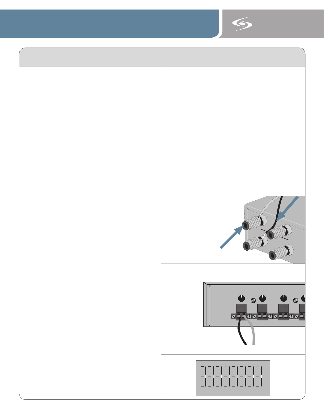
Step 4: Connecting Speaker Wire to
Receiver/Amplifier 850iR (see figure 4)
A. Connect the wire coming from each speaker into the
SPEAKER OUTPUT binding post connectors.
i. Unscrew the red and black caps on the binding
post connectors for all four speakers.
ii. Insert the bare red wire into the hole that was
revealed by unscrewing the red cap. Insert the
bare black wire into the hole on the black binding
post. Repeat with all four speaker wires.
iii. Screw the caps back down onto the wire until they
are secure.
iv. Make sure the speaker on/off switch next to the
jack is switched to the “ON” position.
880iR (see figure 5)
i. Unplug the euro-block style connector from the
SPEAKER 1 jack.
ii. Insert the black wire (-) into the left side of the
connector and lock it down by tightening the screw
on top of the connector.
iii. Insert the red wire (+) into the right side of the
connector and lock it down in the same manner.
iv. Plug the connector back into the SPEAKER 1 jack
and lock it into the amplifier by tightening the two
side screws.
v. The corresponding speaker volume knob should be
left in the 12:00 position.
All LightSPEED speakers should be in
accordance with Uniform Building Code, state
and local building department requirements
Step 5: Equalization
A. Each receiver/amplifier includes an 8-band equalizer
that allows users to fine-tune their classroom based on
different room characteristics. Figure 6 shows the
factory recommended settings for the WMQ speaker.
Since all rooms are different, this is only meant as a
starting point and may require some adjustment.
B. The ideal sound is a crisp, clear sound with no feed back. Volume levels should be set to a point you can
barely hear your own voice. The goal is to try to repli cate the sound of your voice as if the child is sitting
directly in front of you, not to amplify your voice at
high volumes. Because of the classroom size and
constant proximity to the speaker, the system can
product feedback (squealing) if the volume level is
set too high.
C. Return to the “Initial Set-up” section of the user
manual to complete the remaining steps of the
system installation.
Connecting Speaker Wire to Back of Receiver/Amplifier
Figure 4:
820/850iR
RED
Figure 5:
880iR
EQ Setting
Figure 6:
BLACK
 Loading...