

LightSpeed Technologies CNXQ 820 User Manual
CNXQ™ Flat-Panel Ceiling Speaker Installation
CNXQ
Throw
Away
Remaining
Ceiling Tile
Ceiling Tile Grid
CNXQ Speaker
Cross Tee
Ceiling Tile
Instructions for the 820/850/880iR Receiver/Amplifier
LightSPEED
Start your system installation with the
“System Installation” section of the User Manual
Step 1: Selecting Speaker Location
One CNXQ™ Flat Panel Ceiling Speaker is designed
for rooms smaller than 1200 sq. ft. and with a ceiling
height of 9–12 feet.
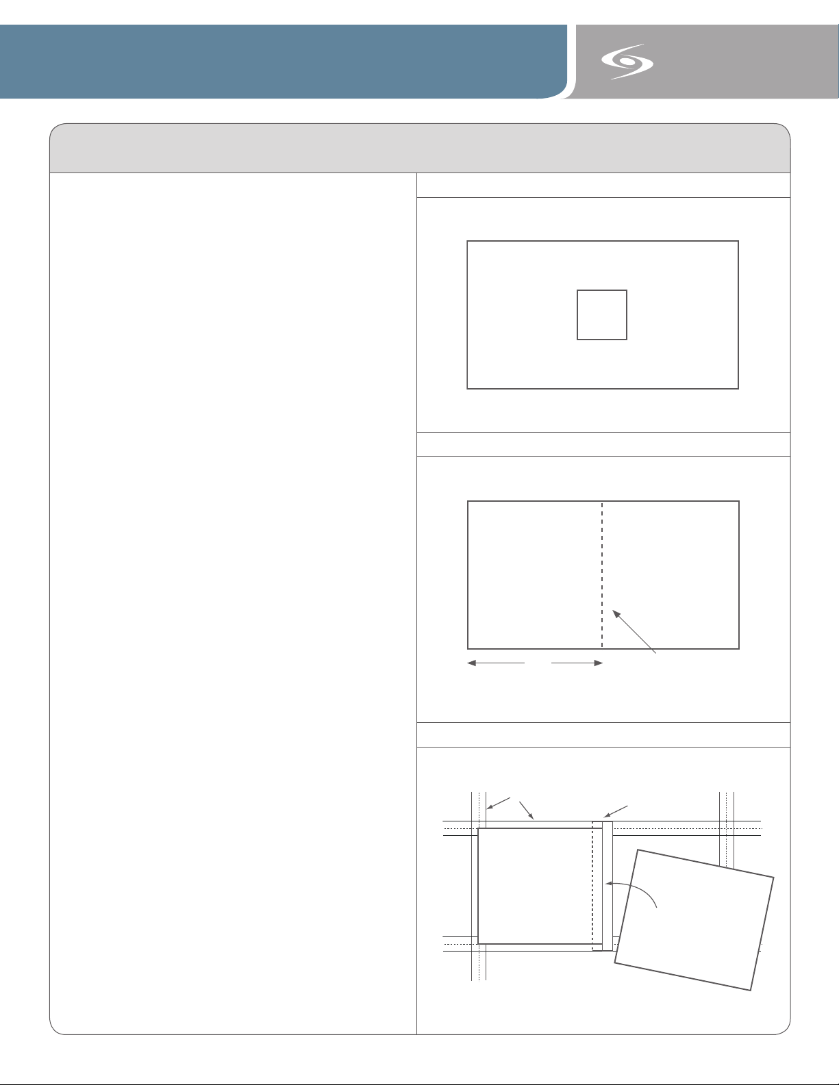
Before starting the system installation, speaker placement
needs to be determined. This speaker is designed to
be mounted in the ceiling in or near the middle of the
classroom (See figure 1.). The speaker lays directly into the
acoustic ceiling grid, so locate the tile that is approximately
in the center of the classroom.
Step 2: Installing and Connecting the Speaker Wire
A. Identify a suitable location for the receiver/amplifier
where it is easily assessable, close to a power outlet,
and at least 6 feet away from any computers.
B. Remove the ceiling tile from the ceiling that was
identified in Step 1.
C. Set the ceiling tile on a flat work surface with patterned
side facing down. The dimensions of the CNXQ Speaker
are 2’ x 2’ Using a straight edge, cut 24” off the
end of a standard 2’ x 4’ ceiling tile as shown in Figure
2. (If the ceiling tile grid is 2’ x 2’, simply remove the
tile and replace with the CNXQ speaker).
D. Locate the coil of speaker wire. To connect the wire to
the speaker, press down on the colored terminals on
the back of the speaker, insert the wire and release
the tab to clamp it in place. Insert the black wire into
the black-tabbed terminal and the red wire into the
red-tabbed terminal.
E. Place the other end of the wire up through the opening
in the ceiling and route over the ceiling tiles and back
down the wall to the receiver/amplifier. (NOTE: when
routing wire overhead, it is important to always follow
local building and electrical codes, securing wire as
required). Do not connect the wires to the receiver
amplifier yet.
F. If installing the speaker into a 2’ x 4’ suspended
ceiling, snap the included cross tee into the suspended
ceiling grid. Locate the slots in the grid at the center of
the 2’ x 4’ area. Insert one end of the tee, then the
other so it locks into place.
G. The speaker has an earthquake strap connected to the
back so it can be tied off to the ceiling structure for
safety purposes. Unscrew one end of the wire from the
back of the speaker to be tied off to the ceiling
supports. If local building codes do not require the use
of an earthquake strap and it is not being used, you
should completely remove the strap from the speaker
so that does not create unwanted vibration.
H. Lay the CNXQ directly onto the ceiling tile grid as
shown in Figure 3. Secure the speaker to the ceiling
with the earthquake strap as required by local building
codes. Speaker wire should also be secured to the
ceiling. DO NOT lay the speaker wire across the back
of the speaker to avoid unwanted vibration.
I. Insert the cut tile back into the ceiling.
All LightSPEED speakers should be in
accordance with Uniform Building Code, state
and local building department requirements
Room Installation: Top View
Figure 1:
Cutting a 2’ x 4’ Ceiling Tile
Figure 2:
24”
Installing the Speaker
Figure 3:
Cut with Straight Edge
SPEAKER
OUTPUTS
250 40 0
70
0
1K 1K 4
2K
5
4K
6K
+1
0
0
-1
0
AUX
VOL
ADJ
COMPUTER
AUDIO INPUT
S
TV/VCR CD/DVD
800i
X
INPU
T
PAGING INPU
T
DC POWER
CHARGER
S24VDC
L
R
SENSOR INPUT
1 2 3 4
AUX
ALD
VOL
ADJ
ALD
OU
T
AUX
OU
T
CH A
PRIORITY
R
L
ADJ
SPEAKER
VOLUME
5
6
CH. B/Audio IN
Audio
IN
OFF
EQUALIZER
250
400
600
1K
1K6 2K5
6K3
4K
+10
0
-10
CNXQ™ Flat-Panel Ceiling Speaker Installation
1
2
Instructions for the 820/850/880iR Receiver/Amplifier
LightSPEED
Start your system installation with the
“System Installation” section of the User Manual
Step 3: Connect Speakers and Wire to the
Receiver/Amplifier
A. Connect the wire coming from the speaker wire to the
receiver/amplifier in the following manner based on the
system type:
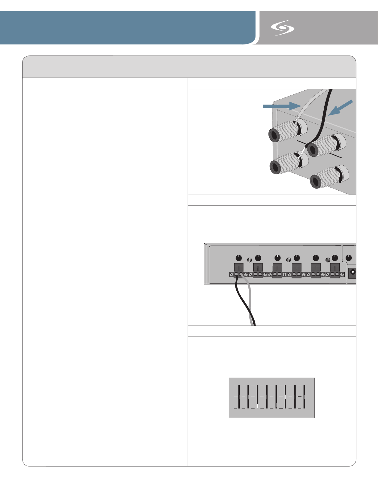
820/850iR (see figure 4)
i. Unscrew the red and black caps on the binding
post connectors.
ii. Insert the bare red wire into the red hole that was
revealed by unscrewing the red cap and the black
wire into the hole on the black connector.
iii. Screw the caps back down onto the wires until
they are secure.
iv. Make sure the speaker on/off switch next to the
jack (850 only) is switched to the “on” position.
880iR (see figure 5)
i. Unplug the euro-block style connector from the
SPEAKER 1 jack.
ii. Insert the black wire (-) into the left side of the
connector and lock it down by tightening the
screw on top of the connector
iii. Insert the red wire (+) into the right side of the
connector and lock it down in the same manner.
iv. Plug the connector back into the SPEAKER 1 jack
and lock it into the amplifier by tightening the two
side screws.
v. The corresponding speaker volume knob should be
left in the 12:00 position.
vi. Make sure the corresponding on/off switch on the
front of the unit is in the “on” position.
B. Speaker wire should be secured to the wall and con cealed if desired with wire mold.
Step 4: Equalization
A. Each receiver/amplifier includes an 8-band equalizer
that allows users to fine-tune their classroom based on
different room characteristics. Figure 6 shows the
factory recommended settings for the CNXQ speaker.
Since all rooms are different, this is only meant as a
starting point and may require some adjustment.
B. The ideal sound is a crisp, clear sound with no feed back. Volume levels should be set to a point you can
barely hear your own voice. The goal is to try to repli cate the sound of your voice as if the child is sitting
directly in front of you, not to amplify your voice at
high volumes. Because of the classroom size and
constant proximity to the speaker, the system can
product feedback (squealing) if the volume level is
set too high.
C. Return to the “Initial Set-up” section of the user
manual to complete the remaining steps of the
system installation.
All LightSPEED speakers should be in
accordance with Uniform Building Code, state
and local building department requirements
Connecting Speaker Wire to Back of 820/850iR
Figure 4:
RED
BLACK
Connecting Speaker Wire to Back of 880iR
Figure 5:
Factory Recommended EQ Setting
Figure 6:
 Loading...