

LightSpeed Technologies 850iR User Manual 2
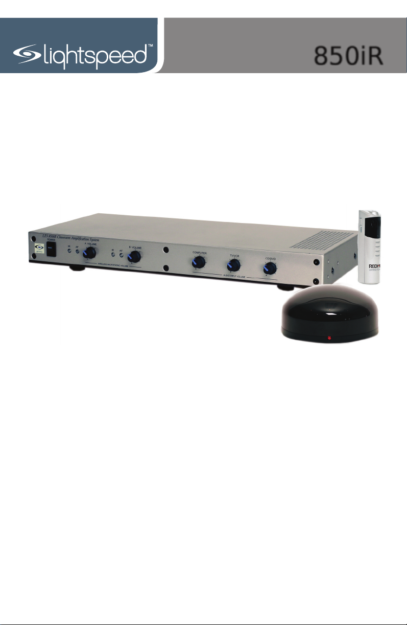
850iR
Classroom Audio System
User Manual
850iR User Manual
850iR User Manual
CONGRATULATIONS!
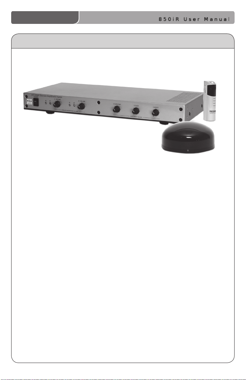
Congratulations on your purchase of the 850iR Classroom Audio
System! This simple, yet powerful technology provides crystal-clear sound
throughout the classroom, allowing every child to hear every word
every time.
As the teacher speaks into the REDMIKE™ classroom microphone, his
or her voice is transmitted to the 850iR and then amplied through the
loudspeaker(s). The standard system includes the 850iR infrared receiver/
amplier, REDMIKE classroom microphone, SR-70F infrared sensor and
speaker package.
The 850iR is a two-channel receiver amplier that allows the use of up to
two microphones simultaneously and up to three additional audio input
sources (such as TV, VCR, DVD, CD, MP3, etc.). In addition, Lightspeed
offers various speaker options that are included with your system to
provide optimal sound in rooms of all shapes and sizes.
The REDMIKE is a wireless, pendant-style transmitter. This
two-channel, rechargeable unit is clipped to a lavaliere cord and worn
around the neck for teacher use, or it can be used like a standard handheld
microphone for the students to pass around when speaking.
850iR User Manual | i
850iR User Manual
850iR User Manual
SAFETY INSTRUCTIONS AND CERTIFICATIONS
CAUTION
RISK OF ELECTRIC SHOCK DO NOT OPEN
CAUTION: TO REDUCE THE RISK OF ELECTRIC SHOCK
DO NOT REMOVE COVER (OR BACK)
NO USER-SERVICEABLE PARTS INSIDE
REFER SERVICING TO QUALIFIED PERSONNEL
The lightning ash with arrowhead symbol
within an equilateral triangle is intended to
alert the user to the presence of uninsulated
“dangerous voltage” within the product’s
enclosure, that may be sufcient magnitude to
constitute a risk of electric shock.
The exclamation point within an equilateral
triangle is intended to alert the user to
the presence of important operating and
maintenance (servicing) instructions in the
literature accompanying the appliance.
CERTIFICATIONS
Complies with 72/23/EEC Low Voltage Directive
and 89/336/EEC Electromagnetic Compatibility
Directive. Compliance was demonstrated to the
following specications as listed in the Ofcial
Journal of the European Union:
EN 60950: Electrical Safety – A1:1993,
A2:1993, A3:1993, A4:1997
EN 55022: RF Emissions, Information
Technology Equipment
EN 55024: EMC Immunity Standard
EN 61000-3-2: Harmonics
EN 61000-3-3: Voltage Fluctuation
Lightspeed Technologies launched a formal
product recycle program in Europe that
complies with the European Union Directive
2002/96/EC on Waste Electrical and Electronic
Equipment (“WEEE Directive”). Please visit our
website at www.Lightspeed-tek.com for more
information.
This product is manufactured using lead-free
processes and is free of other materials
harmful to the environment. It conforms to the
most stringent new European guidelines for
consumer products (RoHS).
Lightspeed is proud to inform that the REDCAT
RCP has achieved the ENERGY STAR® label.
ENERGY STAR qualied products save you
money by reducing energy costs and helps
protect the environment without sacricing
features or performance.
1. Read Instructions—All safety and
operation instructions should be read
before this Lightspeed product is
operated.
2. Retain Instructions—The safety and
operating instructions should be kept
for future reference.
3. Heed Warnings—All warnings on
this Lightspeed product and in these
instructions should be followed.
4. Follow Instructions—All operating
and other instructions should
be followed.
5. Water and Moisture—This
Lightspeed product should not be
used near water.
6. Heat—This Lightspeed product should
be situated away from heat sources
such as radiators, etc.
7. Power Sources—This Lightspeed
product should be connected
to a power supply only of the
type described in the operation
instructions or as marked on this
Lightspeed product.
8. Power Cord Protection—Power
supply cords should be routed so that
they are not likely to be walked upon
or pinched by items placed upon or
against them.
9. Object and Liquid Entry—Care should
be taken so that objects do not fall
onto and liquids are not spilled into
the Lightspeed product.
10. Damage Requiring Service—This
Lightspeed product should be serviced
only by qualied service personnel.
The user should not attempt to service
this Lightspeed product.
11. Prevent Electric Shock—Do not use
this polarized plug with an extension
cord, receptacle or other outlet unless
the blades can be fully inserted to
prevent blade exposure.
ii | 850iR User Manual

850iR User Manual
850iR User Manual
TABLE OF CONTENTS
850iR CLASSROOM AUDIO SYSTEM
Safety Instructions and Certications ........................................................................ii
SECTION 1: System Overview ................................................................................. 1
System Components ............................................................................................. 2
Front Panel Controls ............................................................................................... 3
Rear Panel Controls ............................................................................................... 4
Page First: Emergency Page Priority .................................................................................... 4
REDMIKE Controls and Connections ...................................................................... 6
Attaching the Lanyard to REDMIKE ........................................................................ 7
Cradle Charger Controls and Connections ............................................................. 8
Optional LT-71 Controls and Connections .................................................................. 9
Optional HM-70 Controls and Connections ...........................................................10
SECTION 2: Installation ..........................................................................................11
Unpacking Your System .................................................................................................... 12
Location of the Receiver/Amplier..................................................................................13
IR Sensor Installation ............................................................................................14
Suspended Ceiling Mount .................................................................................................. 15
Wall/Solid Ceiling Mount .................................................................................................... 15
Speaker Installation ........................................................................................................... 16
Audio Integration ...............................................................................................................17
Finalizing Connections ......................................................................................................19
Final Check ..........................................................................................................................20
SECTION 3: Initial Set-up, Charging and Optional Features ................................21
Initial Set-Up: REDMIKE ........................................................................................22
Initial Set-Up: Optional LT-71 ................................................................................23
Initial Set-Up: Optional HM-70 ..............................................................................24
Charging the REDMIKE .........................................................................................25
Charging the Optional LT-71 .................................................................................26
Charging the Optional HM-70 ...............................................................................27
Output to Personal FM Transmitter .......................................................................28
Using the REDMIKE to Amplify External Audio Equipment ....................................29
SECTION 4: Troubleshooting, Daily Use and Warranty.........................................30
Troubleshooting Guide ..........................................................................................31
Daily Use Instructions ...........................................................................................32
Tips on Classroom Audio ......................................................................................33
Warranty Statement .............................................................................................33
System Specications ..........................................................................................34
Individual Components and Optional Accessories ................................................35
User Notes ............................................................................................................36
850iR User Manual | iii

SECTION 1
System Overview
850iR User Manual
1 | 850iR User Manual
850iR User Manual
LT -71
LES 850iR Classroom Amplification System
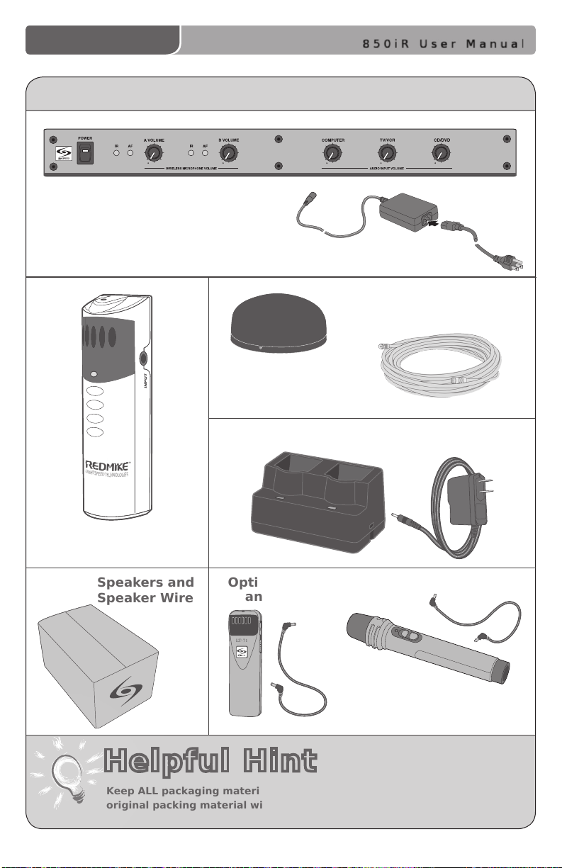
SYSTEM COMPONENTS
850iR Infrared Receiver/Amplier and Power Supply
Sensor Cable
SR-70F Infrared
Sensor
Charging Cradle and Power Supply
REDMIKE Classroom
Microphone
Speakers and
Speaker Wire
Helpful Hint
Keep ALL packaging materials. If the system must be returned, using the
original packing material will be quick, convenient and prevent damage.
Optional LT-71 LightMic
and Charger Cable
Optional HM-70
Handheld Microphone
and Charger Cable
850iR User Manual | 2
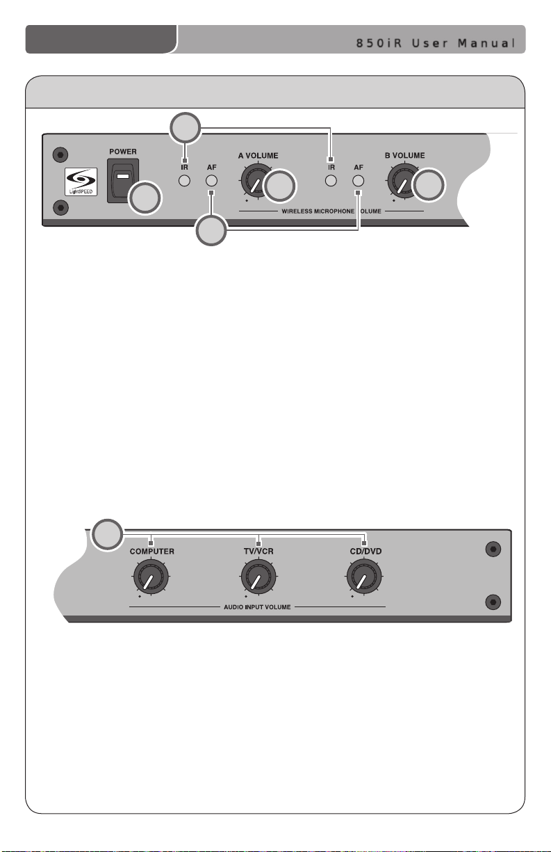
FRONT PANEL CONTROLS
LES 850iR Classroom Amplification System
2
850iR User Manual
1
3
1. POWER Switch/POWER Indicator:
This switch is used to turn the
850iR ON (switch up), or OFF
(switch down). When the POWER
switch is in the ON position, the
POWER light will glow red.
2. IR Indicators (IR): These lights will
glow red when the corresponding
microphone is turned on. This light
conrms the 850iR is receiving
a steady infrared signal.
6
4
3. AF Indicators (AF): These lights
ash green when audio (voice)
from the microphone is detected.
4. A VOLUME: Controls the volume
level of the teacher microphone
that is switched to Channel A.
Rotating the knob clockwise
increases output level.
5. B VOLUME: Controls the volume
level of the optional second
microphone that is switched to
Channel B. Rotating the knob
clockwise increases output level.
5
6. AUDIO INPUT VOLUME:
• COMPUTER: Controls the volume
of audio coming from a computer
connected to the rear panel
COMPUTER INPUT jack.
• TV/VCR: Controls the volume of
the source connected to the rear
panel TV/VCR INPUT.
3 | 850iR User Manual
• CD/DVD: Controls the volume
of the source player
connected to the rear panel
CD/DVD INPUT.
SPEAKER OUTPUTS
OFF
OFF
OFF
OFF
ON
ON ON
ON
VOL.
ADJ.
ALD OUT
AUX OUT
VOL.
ADJ.
COMPUTER
AUDIO INPUTS
TV/VCR CD/DVD
800iX
INPUT
PAGING INPUT
DC POWER CHARGERS
24VDC
L L R R
1 2 3
4
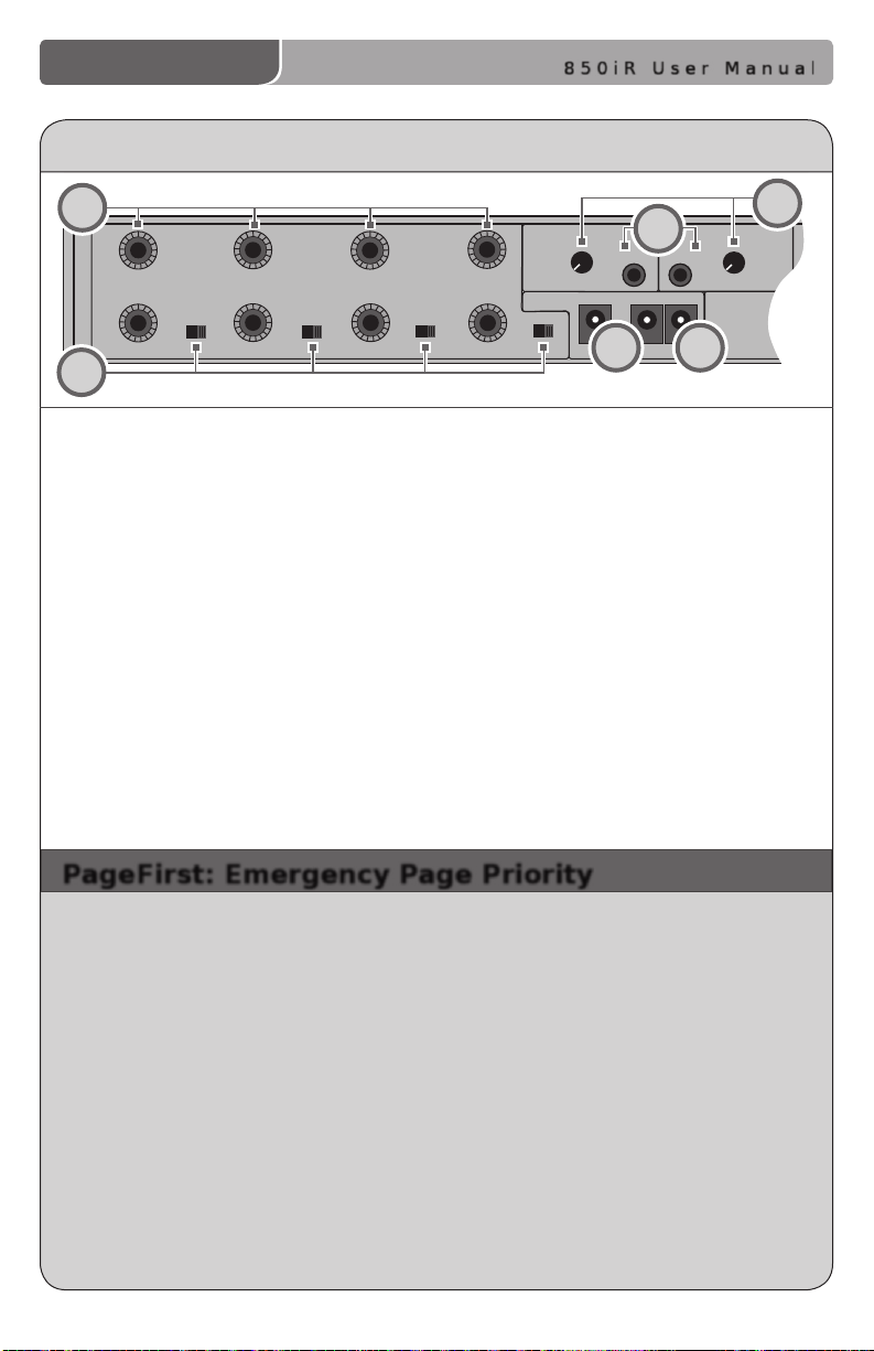
REAR PANEL CONTROLS
850iR User Manual
1
2
1. SPEAKER OUTPUTS (1-4): These
binding post connectors are used to
connect the 850iR to the loudspeakers.
Depending on the speaker package, all
the outputs may not be used.
2. SPEAKER ON/OFF: These individual
speaker switches can be used to turn
off the audio in a specic area of the
classroom where there may be a
learning group or quiet time.
3. DC POWER: Plug the 24 V power
supply into this jack.
6
5
3
4. CHARGERS: These jacks can be used
to charge the optional LightMic or
handheld mic as an alternative to
connecting them to the REDMIKE
cradle charger.
5. ALD/AUX AUDIO OUT: These output
jacks send audio signal to external
equipment such as a recorder or an
assistive listening device like the
LES-370 Personal FM System.
6. ADJ: These controls adjust the output
evel of the audio being sent out of
the receiver/amplier via the
ALD/AUX AUDIO OUT jacks.
4
PageFirst: Emergency Page Priority
This optional feature interfaces with an independent classroom paging
system. When the page is broadcast, the system is muted, ensuring important
and emergency school-wide messages are never missed.
How it works:
1. PageFirst sensor clip is hung around the lead wires attached to the in-room
paging speaker.
2. The clip is hard-wired to the 850iR.
3. As a page is broadcast, the sensor clip detects the audio signal though
induction and immediately mutes the 850iR.
4. When the page is over, the audio to the 850iR returns to normal.
(For full installation instructions refer to the install sheet included with the
optional PageFirst sensor.)
850iR User Manual | 4
250 400
700
1K 1K4
2K5
4K
6K
+10
0
-10
COMPUTER
AUDIO INPUTS
TV/VCR CD/DVD
800iX
INPUT
PAGING INPUT
ADJ
L L R R
SENSOR INPUTS
SENSOR
SHORT
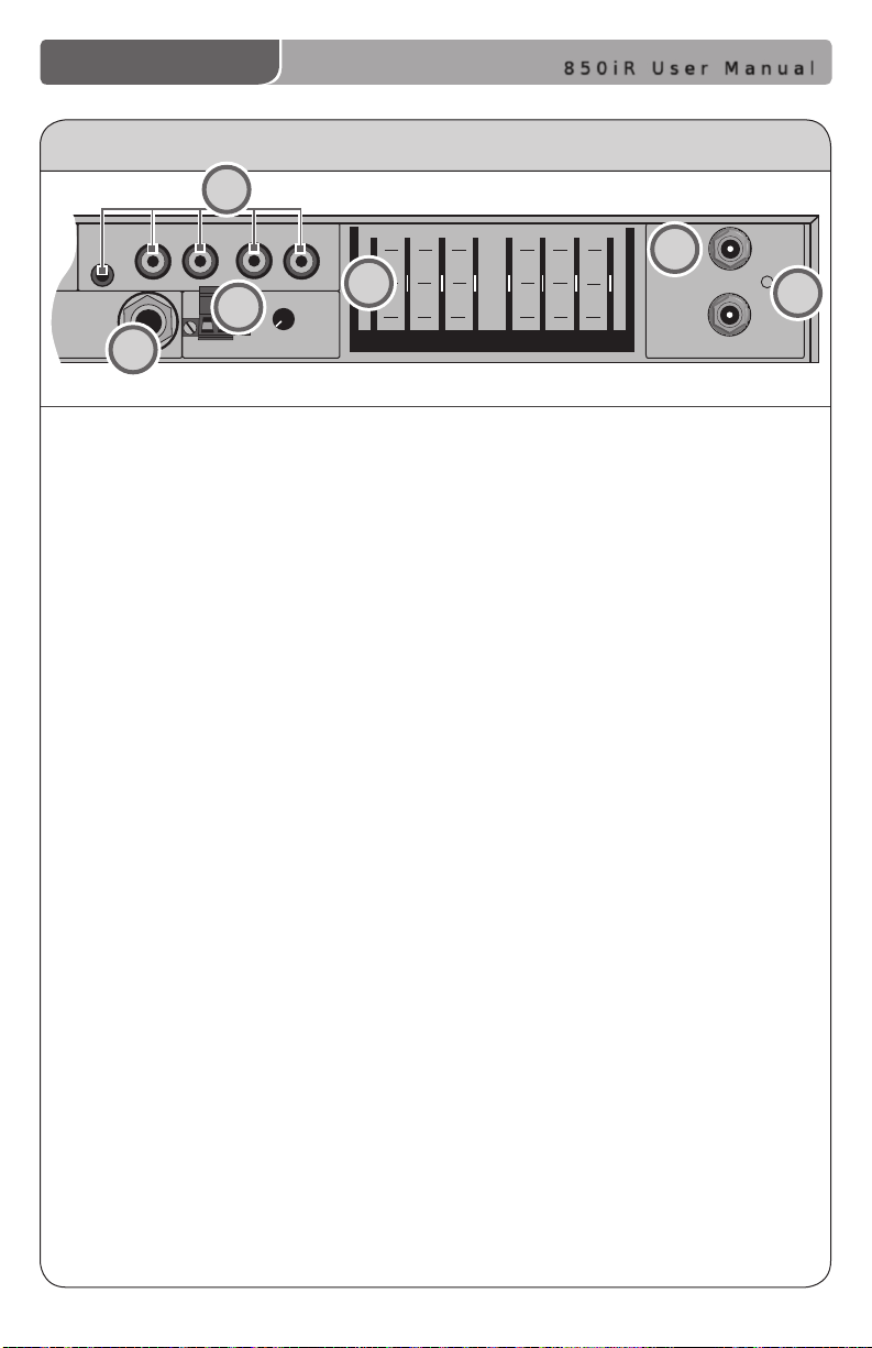
REAR PANEL CONTROLS (cont’d)
7
10
9
8
850iR User Manual
11
12
7. AUDIO INPUTS:
• COMPUTER: Accepts stereo signal
from computer via 3.5 mm cable.
• TV/VCR: Accepts stereo signal
from TV/VCR via RCA cable.
• CD/DVD: Accepts stereo signal
from CD/DVD player via RCA cable.
8. 800iX INPUT: This input jack allows
for interface with the Lightspeed
800iX wireless microphone system,
which adds up to additional two
microphone channels.
9. PAGING INPUT and ADJ:
When the optional PageFirst sensor
is connected to this input, the audio
being amplied through the
850iR will mute as an announcement
is made through the school PA
system, ensuring important
messages are never missed.
10. 8-BAND GRAPHIC EQUALIZER: The
sliding controls adjust the levels of
the various audio frequencies. This
allows the installer to properly
equalize the system to produce
optimum sound quality.
11. SENSOR INPUT: The IR sensor cable
connects to either of these two
inputs. Connect additional sensors
to the 850iR to cover large or
odd-shaped classrooms.
12. SENSOR SHORT: This LED glows red
when there is a short in the sensor
or cable.
5 | 850iR User Manual
850iR User Manual
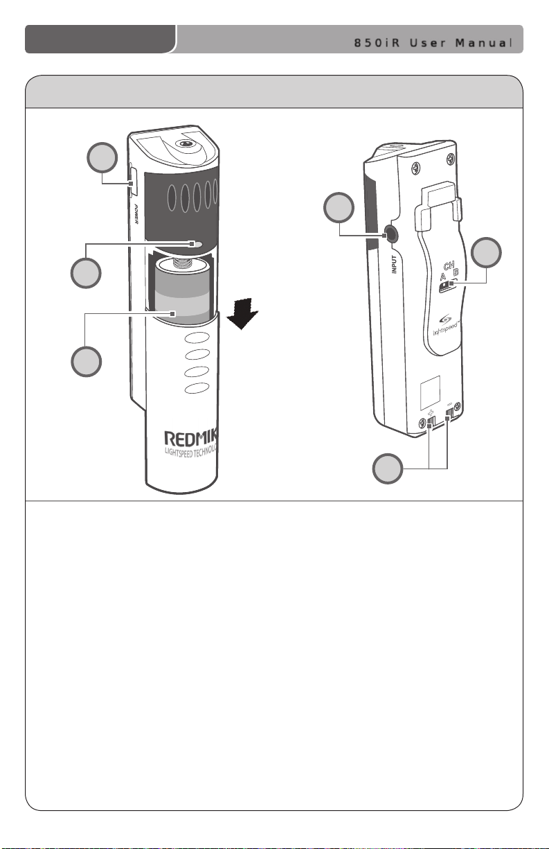
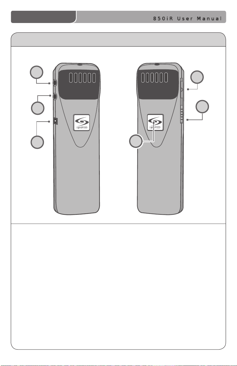
REDMIKE CONTROLS AND CONNECTIONS
1
4
2
3
5
1. POWER BUTTON: Press this button
to turn the REDMIKE ON, press
again to turn it OFF (mute).
2. POWER/LOW BATTERY INDICATOR:
A BLUE light indicates the REDMIKE
is on and fully charged. A RED light
indicates a charge is needed.
3. BATTERY COMPARTMENT: To
access the battery compartment,
slide the door downward.
The battery should only be
replaced by a Lightspeed AA
rechargeable sensing battery
(part # BA-NH2A27).
6
4. AUDIO/MICROPHONE INPUT: Use this
input to plug in a laptop, MP3 player
or other audio source to wirelessly
transmit audio to be played through
the system. Alternatively, an external
microphone can be connected.
5. CHANNEL SELECT SWITCH (CH A/B):
This switch allows for selection between
Channel A or B. If you are using a single
microphone, we recommend using
Channel A.
6. CHARGER CONTACTS (+ -): These
contacts interface with the charging
tabs in the BC-RMCC cradle charger
for daily charging. Simply place the
REDMIKE in the charger.
850iR User Manual | 6
850iR User Manual
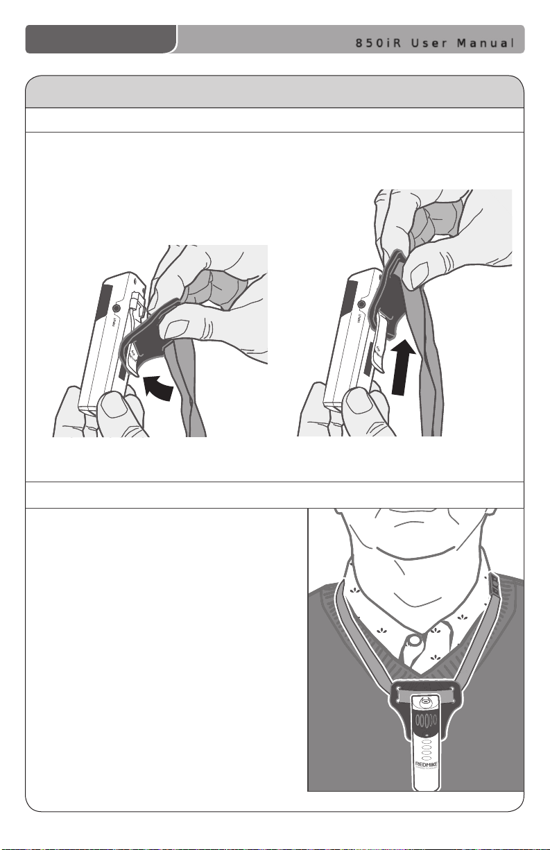
ATTACHING THE LANYARD TO REDMIKE
1. ATTACH THE FOAM HOLDER
Insert the REDMIKE clip into the slot
at the bottom of the foam holder.
2. POSITION THE REDMIKE
Slip the REDMIKE with lanyard
around the neck. Adjust the neck
strap so the top of the microphone
rests just below your collarbone.
7 | 850iR User Manual
850iR User Manual
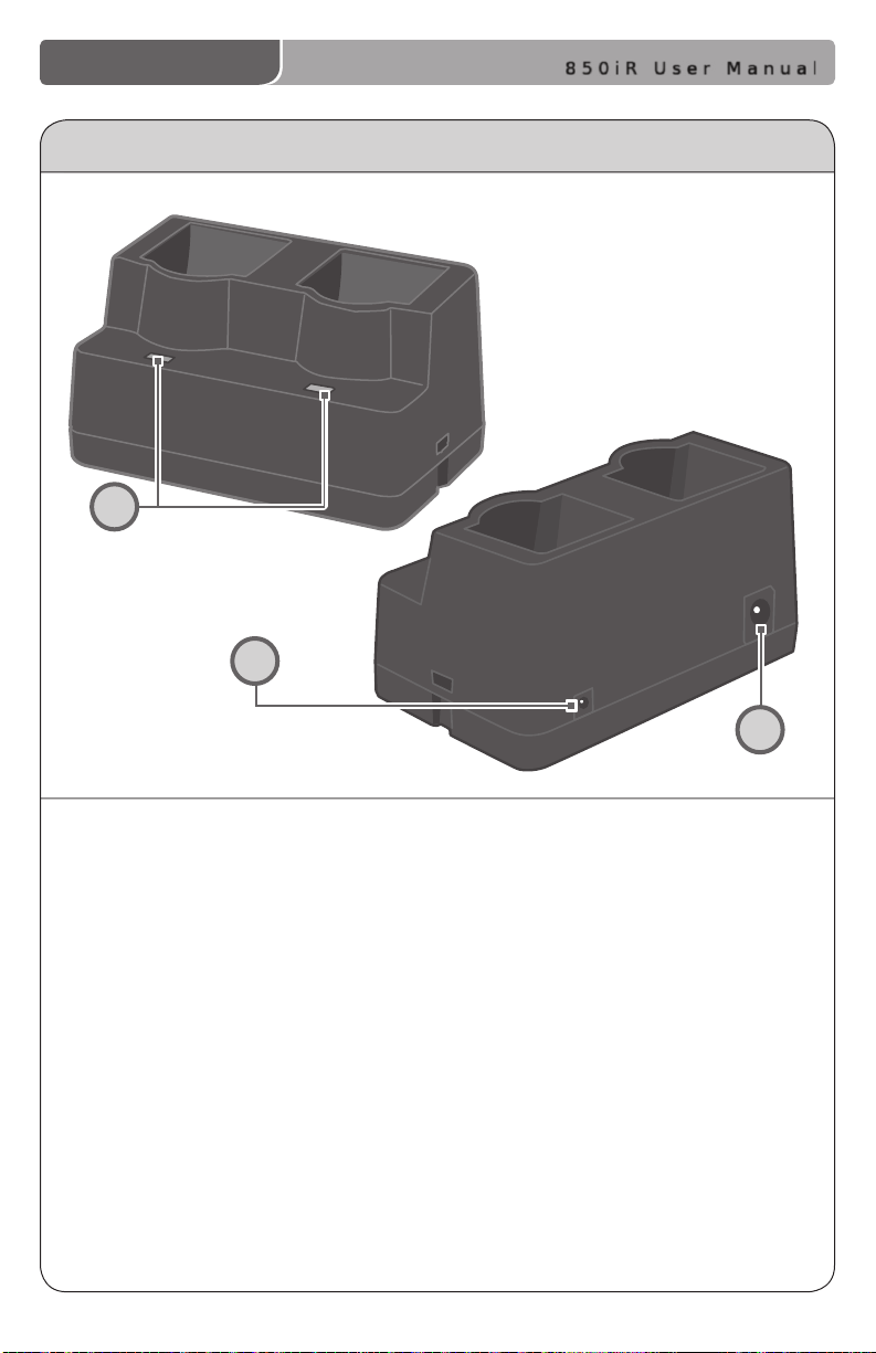
CRADLE CHARGER CONTROLS AND CONNECTIONS
1
2
1. CHARGE INDICATORS: The light
glows RED while the REDMIKE is
charging. When fully charged, the
light will glow GREEN.
2. DC POWER PORT: Connect the DC
power cord here.
3
3. OPTIONAL CHARGING PORT: Plug the
charging cord for the optional LT-71 or
the HM-70 microphones here.
850iR User Manual | 8
850iR User Manual
LT- 71
LT- 71
OPTIONAL LT-71 CONTROLS AND CONNECTIONS
4
5
6
1. ON/OFF/MUTE Switch: This switch
turns LT-71 ON or OFF (mute).
2. Channel Select Switch (CH A/B):
This switch allows for selection
of Channel A or B. If you are
using a single microphone, we
recommend using Channel A.
3. Power/Charge Indicator: The
light glows BLUE when the LT-71
is powered ON, RED when being
charged.
4. External Microphone Input (MIC):
Use the 3.5mm MIC jack for the
optional TK-250 headset microphone
(part# MC-TK250LTM).
1
2
3
5. Auxiliary (AUX): Plug a laptop, MP3
player or other audio source into
this jack to wirelessly transmit the
audio signal to be played through
the system.
6. Charger Input (CHARGER): Plug
the charging cable from the
charger into this jack for daily
charging. The LED on the front will
glow RED to indicate charging.
9 | 850iR User Manual
 Loading...