

Page 1
TriCode
WARNING
TM
TCG2 Dual Channel Receiver
SPECIFICATIONS
Output Rating: 5 Amps 28VAC or DC Max.
Power: 12VDC or 18 to 34VAC/DC, @ 30ma
RF Frequency: 300 or 310MHz
Accessory Transmitters:
Antenna Extension Kit: TCEXT
This device complies with FCC Rules Part 15 and IC
Canada Rules and Regulations. Operation is subject
to the following two conditions: (1) This device may
not cause harmful interference and (2) this device
must accept any interference received, including
interference that may cause undesired operation.
F.C.C. rules prohibit adjustments to or modification of
receiver and/or remote control transmitter circuitry
except for changing the code setting and replacing
remote control transmitter battery. THERE ARE NO
OTHER SERVICEABLE PARTS.
The TriCodeTMdigital receivers are designed for use
with automatic garage/gate operators and access
control systems. All TriCode
matched with Linear/Delta-3TM, Multi-CodeTM, and
StanleyTMradio products which may already be
installed.
TM
The TriCode
1024 different digital codes. For Linear/Delta-3
compatible products, 256 different digital codes are
available. The codes are set using a 10-position DIP
switch system.
radio format provides a potential of
TC1, TC2 and TC4
TM
products may be
TM
TABLE OF CONTENTS
U.S. Patent Pending
INSTALLATION AND SERVICE INFORMATION ARE
AVAILABLE 6 DAYS A WEEK CALL OUR TOLL FREE
NUMBER
1-800-528-3536
HOURS 7:00 TO 3:30 p.m. (Mountain Std. Time)
MONDAY Through SATURDAY
OR CONTACT US THROUGH THE WEB AT
WWW. CHAMBERLAINGROUP.COM
WARNING
Children operating or playing with a garage
door /gate opener can injure themselves and
others.
serious injury or death.
to operate the door control push button or the
remote control transmitters.
Install the receiver (and all door control push
buttons) out of the reach of children and away
from all moving parts of the door and door
hardware, but
The door/gate could close and cause
Do not allow children
where the door/gate is visible.
DESCRIPTION PAGE
Setting Power Supply Selection..........................2
Setting Output Relay Mode.................................2
Setting the Configuration Switch.........................3
Setting DIP Switch...............................................3
Power Supply Connections.................................4
WARNING
Disconnect power to opener before installing
receiver or removing/replacing receiver cover.
Page 2
POWER & OUTPUT RELAY SWITCH SETTINGS
CAUTION:
To avoid possibility of duplicating
codes in adjacent systems, all transmitters and
receivers should be re-coded prior to operation.
Unless using maximum number of codes the
following four codes should not be used:
· All DIP Switches ON
· All DIP Switches OFF
· DIP Switches alternating ON/OFF
· DIP Switches alternating OFF/ON.
Receivers should be installed at least 5 feet apart to
avoid cross-talk. After completing installation,
operate transmitter outside of building to make
certain the chosen DIP switch setting does not
operate with nearby garage door operators and/or
security systems. If so, select another DIP switch
setting and check the coded signal again. Repeat as
necessary.
RECEIVER MOUNTING
Mount receiver to wall using #6 hardware (Not
Supplied). Hardware used will depend on mounting
application. (Refer to figure 1 for receiver mounting
hole locations).
ANTENNA MOUNTING
Screw on antenna clockwise and slide rubber boot
down to meet o-ring.
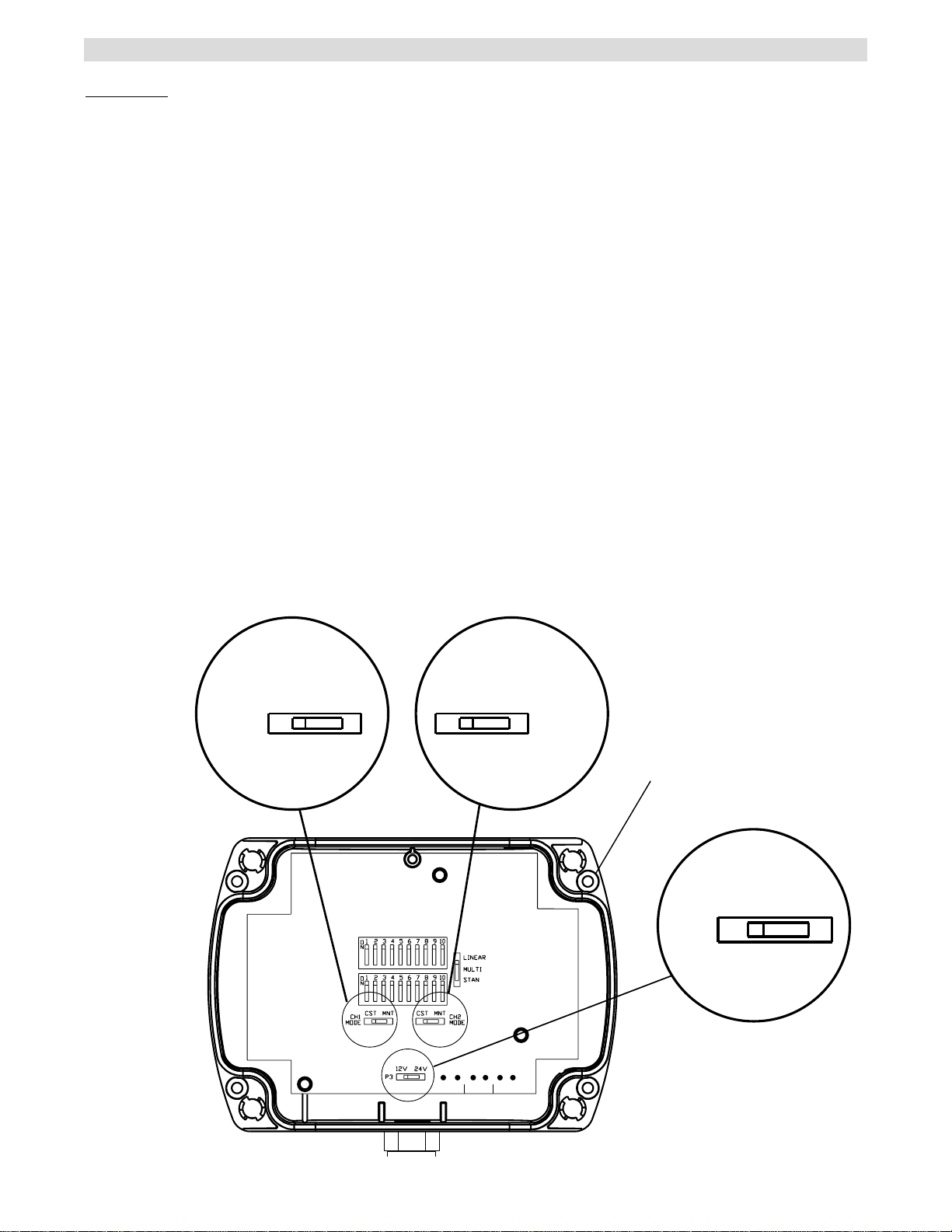
Step 1 Power Supply Selection Setting
The TriCode
input if 12 volt is required.
Remove front cover of receiver by turning screws
counterclockwise a 1/4 of a turn until each releases.
Set jumper (P3) to either 12 or 24 volt setting
depending on your power input (Refer to figure 1).
Step 2 Setting Output Relay Mode
The TriCode
relay output “MNT”.
(a) Momentary mode: The output relay will be on for
.5 seconds before turning off.
(b) Constant pressure mode: Output relay is
continuously on while receiving matching/valid ID
code from transmitter. The output relay will turn off
immediately once receiver does not received a
matching/valid ID code from the transmitter.
If constant pressure mode is desired, move mode
jumper from “MNT” to “CST” (Refer to figure 1).
NOTE: The relay output is an isolated normally open
contact.
TM
receiver is factory set for 24 volt power
TM
receiver is factory set for momentary
FIGURE 1
CH1-MODE
CH1
MODE
RELAY
CST MNT
RELAY
CH2-MODE
CST MNT
CH2
MODE
MOUNTING HOLES
(4 CORNERS)
JUMPER
(P3)
12V 24V
P3
24V AC/DC CH1 N/O CH2 N/O
2
Page 3

CONFIGURATION & DIP SWITCH SETTINGS
Step 3 Setting the Configuration Switch
The TriCodeTMreceiver is factory set for Linear/Delta-
TM
.
3
Locate the configuration switch and set it to the
desired RF mode of operation
(Refer to figures 2 and 4)
Modes are as follows:
Linear/Delta-3TM:
works with all “Linear/Delta-3TM”
transmitters transmitted at 310 MHz using 8-bits ID
system.
MultiTM:
works with all “Multi-CodeTM” transmitters
transmitted at 300 MHz using 10-bits ID system.
StanleyTM:
works with all “StanleyTMradio” transmitters
transmitted at 310 MHz using 10-bits ID system.
FIGURE 2
CONFIGURATION
SWITCH
DELTA-3/ LINEAR
MULTI-CODE
STANLEY
TM
310 MHz
TM
TM
300 MHz
310 MHz
Step 4 Setting DIP Switch
The TriCode
TM
receiver DIP switch CH1 is factory set
OFF (1-10) and CH2 is factory sett ON (1-10).
Locate the 10 position DIP Switch. If this is a new
.
installation using TriCode
TM
transmitters, randomly set
switches matching those of the transmitters. Never
use factory setting. If receiver is used with
TM
Linear/Delta-3
, Multi-codeTMor Stanley
transmitters, match the receiver DIP Switch to the
above transmitters. Some transmitters may use
toggle switches and it may be difficult to determine
‘ON’ & ‘OFF’. If so, try reversing the setting on the
TM
TriCode
Note: In 'LINEAR/DELTA-3
DIP Switch (Refer to figures 3 and 4).
TM
' mode (8-bits system)
the last 2 bits (DIP #9 & 10) settings are ignored.
They can be left in either ‘ON’ or ‘OFF’ settings.
FIGURE 3
MULTI/ STANLEY
(1 THRU 10)
LINEAR/ DELTA-3
(1 THRU 8)
TM
tm
TM
FIGURE 4
CHANNEL 2 DIP SWITCH
CHANNEL 1 DIP SWITCH
DIP
SWITCH
1 2 3 4 5 6 7 8 9 10
O
N
O
F
F
DIP
SWITCHES
CONFIGURATION
SWITCH
24V AC/DC CH1 N/O CH2 N/O
DELTA-3/LINEAR
MULTI-CODE
STANLEY
TM
TM
TM
3
Page 4

POWER CONNECTIONS
Step 5 Power Supply Connections
A prewired gasketed pigtail is included for your
convenience (See figure 5 for outgoing wires).
NOTE: For internal wire connections refer to figure 6.
FIGURE 5
FIGURE 6
WIRE
ENTRY
24V
AC/DC
CH1
N/O
24V AC/DC CH1 N/O CH2 N/O
RED
POWER
SUPPLY
12V/24V
BLACK
WHITE/GREEN
WHITE/YELLOW
RED
BLACK
WHITE/GREEN STRIPE
WHITE/YELLOW STRIPE
BLUE/BROWN STRIPE
BLUE/ORANGE STRIPE
BLUE/BROWN
CH2
N/O
© 2000, The Chamberlain Group, Inc.
01-17469C All Rights Reserved
BLUE/ORANGE
 Loading...