

Liftmaster SW470 User Manual
CONTROLLER BOARD
GL
MODEL SW470
MEDIUM DUTY SWING GATE OPERATOR
Serial # ________________________
(located on electrical box cover)
Installation Date _________________
2 YEAR WARRANTY
MODEL SW490
HEAVY DUTY SWING GATE OPERATOR
INTENDED FOR PROFESSIONAL INSTALLATION ONLY.
VISIT WWW.LIFTMASTER.COM TO LOCATE A PROFESSIONAL
INSTALLING DEALER IN YOUR AREA.
THIS MANUAL IS TO BE LEFT WITH THE PROPERTY OWNER.
MODELS SW470 AND SW490 ARE FOR VEHICULAR PASSAGE GATES
ONLY AND NOT INTENDED FOR PEDESTRIAN PASSAGE GATE USE.

2
WARNING WARNING
WARNING
WARNING WARNING
WARNING
CAUTION CAUTION
WARNING
WARNING
TABLE OF CONTENTS
OPERATOR SPECIFICATIONS
Carton Inventory . . . . . . . . . . . . . . . . . . . . . . . . . . . . . . . . . . . . . . 3
Operator Dimensions and Specifications . . . . . . . . . . . . . . . . . . . 4
UL325 Model Classifications . . . . . . . . . . . . . . . . . . . . . . . . . . . . 5
OPERATOR WARNINGS
Suggested Safety Protection Device Locations. . . . . . . . . . . . . . . 6
Safety Installation Information . . . . . . . . . . . . . . . . . . . . . . . . . . . 7
Gate Construction Information . . . . . . . . . . . . . . . . . . . . . . . . . . . 8
Safety for Swing and Ornamental Grill Type Gates . . . . . . . . . . . . 9
Warranty Sign Placement . . . . . . . . . . . . . . . . . . . . . . . . . . . . . . . 9
INSTALLATION
Post Mounting (SW470) . . . . . . . . . . . . . . . . . . . . . . . . . . . . . . . 10
Pad Mounting (SW470) . . . . . . . . . . . . . . . . . . . . . . . . . . . . . . . 11
Pad Mounting (SW490) . . . . . . . . . . . . . . . . . . . . . . . . . . . . . . . 12
Control Arm and Gate Bracket Installation (SW470). . . . . . . . . . 13
Control Arm Assembly (SW490) . . . . . . . . . . . . . . . . . . . . . .14-15
Manual Disconnect . . . . . . . . . . . . . . . . . . . . . . . . . . . . . . . . . . . 15
WIRING
Power Wiring Installation . . . . . . . . . . . . . . . . . . . . . . . . . . . . . . 16
On/Off Switch Power Wiring. . . . . . . . . . . . . . . . . . . . . . . . . . . . 17
Stop/Reset Button Control Wiring . . . . . . . . . . . . . . . . . . . . . . . 17
ADJUSTMENT
Programming the Radio Receiver. . . . . . . . . . . . . . . . . . . . . . . . 18
Limit Switch Adjustment. . . . . . . . . . . . . . . . . . . . . . . . . . . . . . . 19
RPM Sensor (Hall Effect) Adjustment. . . . . . . . . . . . . . . . . . . . . 20
SAMS (Sequenced Access Management System) . . . . . . . . . . . 21
Accessory Wiring . . . . . . . . . . . . . . . . . . . . . . . . . . . . . . . . . . 22-23
Control Board Illustration . . . . . . . . . . . . . . . . . . . . . . . . . . . . . . 24
Controller Programming and Features . . . . . . . . . . . . . . . . . .25-26
Program Settings . . . . . . . . . . . . . . . . . . . . . . . . . . . . . . . . . .27-28
TROUBLESHOOTING. . . . . . . . . . . . . . . . . . . . . . . . . . . . .29-30
MAINTENANCE
Operator Maintenance. . . . . . . . . . . . . . . . . . . . . . . . . . . . . . . . . 31
Single Phase Wiring Diagram (SW470) . . . . . . . . . . . . . . . . . . . 32
Single Phase Wiring Diagram (SW490) . . . . . . . . . . . . . . . . . . . 33
Three Phase Wiring Diagram (SW490). . . . . . . . . . . . . . . . . . . . 34
Control Connection Diagrams . . . . . . . . . . . . . . . . . . . . . . . . . . . 35
Repair Parts and Illustrated Parts - SW470 . . . . . . . . . . . . . . . . 36
Repair Parts and Illustrated Parts - SW490 . . . . . . . . . . . . . . . . 37
Safety Accessories for Secondary Entrapment Protection . . . . . 38
NOTES . . . . . . . . . . . . . . . . . . . . . . . . . . . . . . . . . . . . . . . . .39
WARRANTY POLICY AND SERVICE . . . . . . . . . . . . . . . .40
IMPORTANT NOTE
• BEFORE attempting to install, operate or maintain the operator,
you MUST read and fully understand this manual and follow all
safety instructions.
• These instructions are intended to highlight certain safety related
issues. These instructions are not intended to be comprehensive.
Because each application is unique, it is the responsibility of the
purchaser, designer, installer and end user to ensure that the
total gate system is safe for its intended use.
Mechanical
Electrical
When you see these Safety Symbols and Signal Words on the
following pages, they will alert you to the possibility of serious
injury or death if you do not comply with the warnings that
accompany them. The hazard may come from something
mechanical or from electric shock. Read the warnings carefully.
When you see this Signal Word on the following pages, it will alert
you to the possibility of damage to your gate and/or the gate
operator if you do not comply with the cautionary statements that
accompany it. Read them carefully.
CARTON INVENTORY
Before beginning your installation check that all components were
supplied and received undamaged. Refer to list below for factory
supplied parts.
HARDWARE KITS SW470 (K77-SW470) & SW490 (K77-SW490)
PART NO. DESCRIPTION QTY.
SW470
02-401-SP Stop Button 1
10-2108-T Arm Channel 1
10-2109 Extension Arm 1
10-2111 Gate Bracket 1
40-3505 Warning Sign 2
80-2103 Black Plastic Knob 2
82-HN38-18 3/8 x 1-1/2 Hex Head Bolt 2
82-SB50-08 1/2-13 x 1/2 Shoulder Bolt 2
84-FN-38 3/8-16 Serrated Flanged Nut 4
85-FW-38 3/8" Flat Washer 2
SW490
02-401-SP Stop Button 1
06-2025-T Arm Channel 1
08-2001 Extension Arm 2
10-2011 Gate Bracket 1
70-18618 Warning Sign 1
10-3900 39" Galvanized Steel Pipe 1
11-18619 Pivot Pin 1
12-10172 3/4 Bushing 2
40-18627 Label, Disconnect 1
40-3505 Warning Sign 2
80-207-20 3/8 x 3/8 x 1-1/2 Key 1
80-575 3/4 Flat Washer 4
82-HN38-16 3/8-16 x 1 Hex Head Bolt 2
82-HN75-28 3/4-10 x 3 Hex Head Bolt 1
82-NH38-06CP 3/8-16 x 3/8 Cone Point Set 6
84-RH-75 3/4-10 Hex Nut 1
85-LS-38 3/8 Lockwasher 2
86-CP05-300 Cotter Pin 2
3
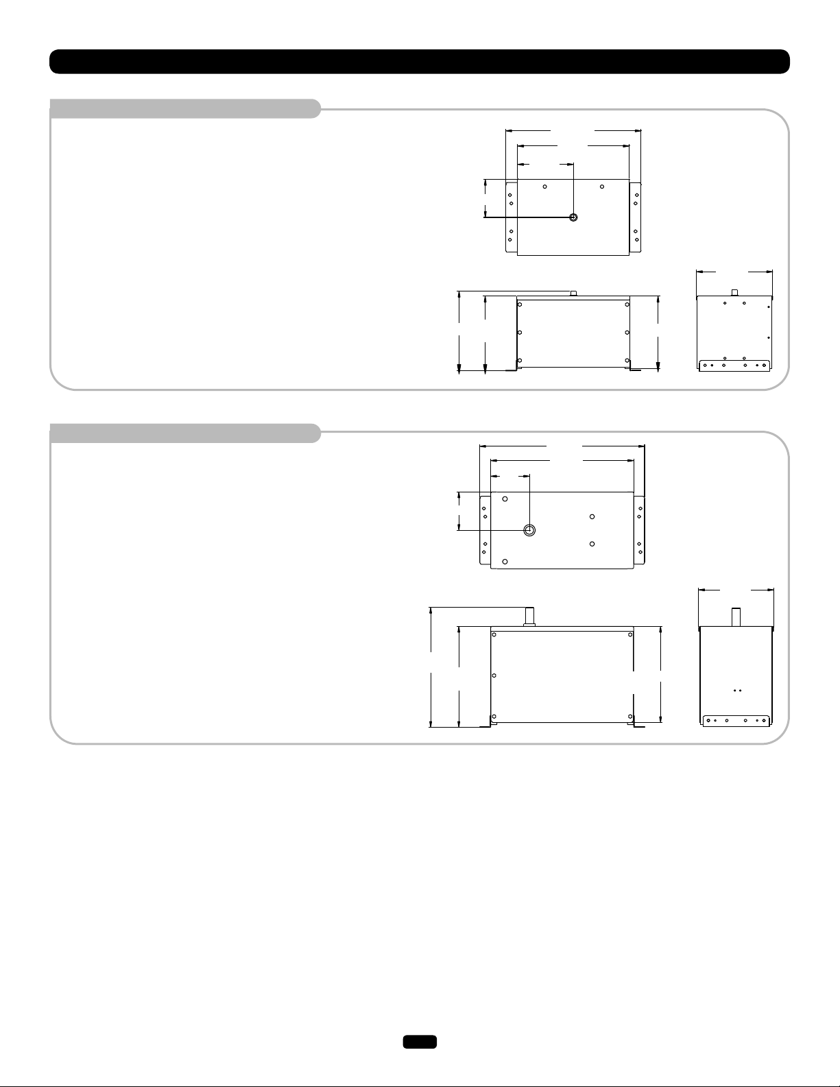
OPERATOR DIMENSIONS AND SPECIFICATIONS
MODEL SW470
• 1/2 HP Motor
Maximum Gate Weight – 500 lbs. (226.8 kg)
Maximum Gate Width – 12 ft. (3.7 m)
MODEL SW490
• 1 HP Motor
Maximum Gate Weight – 1000 lbs. (453.6 kg)
Maximum Gate Width – 22 ft. (6.7 m)
14.25"
(36.2 cm)
7.03"
(17.9 cm)
6.81"
(17.3 cm)
13.38"
(34 cm)
7.12"
(18.1 cm)
(61.6 cm)
10"
(25.4 cm)
30.24"
(76.8 cm)
26.24"
(66.7 cm)
24.25"
20"
(50.8 cm)
13" (33 cm)
13.63"
(34.6 cm)
22"
(55.9 cm)
18.5"
(47 cm)
17.63"
(44.8 cm)
13.75"
(35 cm)
4
Moving Gate Can Cause
Injury or Death
KEEP CLEAR! Gate may move at any
time without prior warning.
Do not let children operate the gate or
play in the gate area.
This entrance is for vehicles only.
Pedestrians must use separate entrance
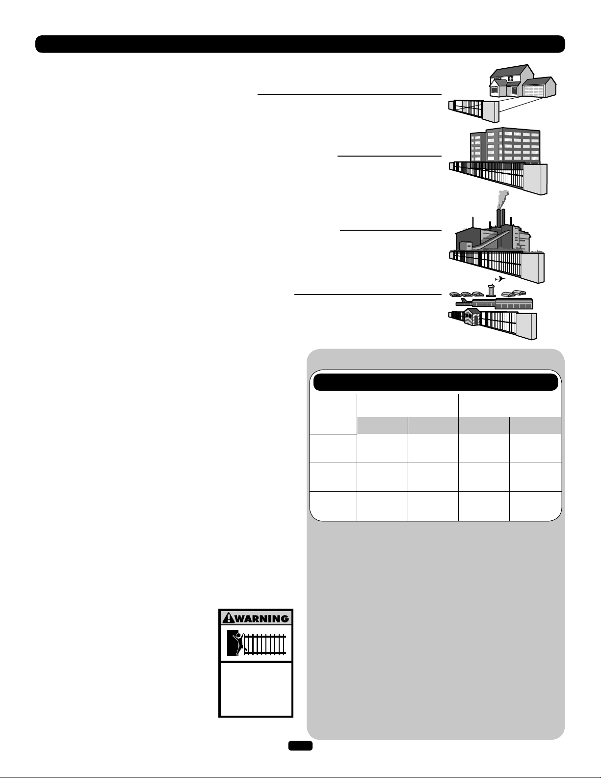
UL325 MODEL CLASSIFICATIONS
The SW470 and SW490 are intended for use with vehicular swing gates. The opener can be used in
Class I, Class II, Class III and Class IV applications.
CLASS I – RESIDENTIAL VEHICULAR GATE OPERATOR
A vehicular gate operator (or system) intended for use in a home of one-to four single family dwellings,
or a garage or parking area associated therewith.
CLASS II – COMMERCIAL/GENERAL ACCESS VEHICULAR GATE OPERATOR
A vehicular gate operator (or system) intended for use in a commercial location or building such as a
multi-family housing unit (five or more single family units) hotel, garage, retail store or other building
servicing the general public.
CLASS III – INDUSTRIAL/LIMITED ACCESS VEHICULAR GATE OPERATOR
A vehicular gate operator (or system) intended for use in a industrial location or building such as a
factory or loading dock area or other location not intended to service the general public.
CLASS IV – RESTRICTED ACCESS VEHICULAR GATE OPERATOR
A vehicular gate operator (or system) intended for use in a guarded industrial location or building such
as an airport security area or other restricted access locations not servicing the general public, in which
unauthorized access is prevented via supervision by security personnel.
SAFETY ACCESSORY SELECTION
All UL325 compliant LiftMaster gate operators will accept external
entrapment protection devices to protect people from motorized
gate systems. UL325 requires that the type of entrapment
protection correctly matches each gate application. Below are the
six types of entrapment protection systems recognized by UL325
for use on this operator.
ENTRAPMENT PROTECTION TYPES
Type A: Inherent obstruction sensing system, self-contained
within the operator. This system must sense and initiate
the reverse of the gate within two seconds of contact
with a solid object.
Type B1: Connections provided for a non-contact device, such as a
photoelectric eye can be used as a secondary protection.
Type B2: Connections provided for a contact sensor. A contact
device such as a gate edge can be used for secondary
protection.
Type C: Inherent adjustable clutch or pressure relief valve.
Type D: Connections provided for a control requiring continuous
pressure to operate the operator
open and close.
Type E: Built-in audio alarm. Examples
include sirens, horns or buzzers.
NOTE: UL requires that all installations must
have warning signs placed in plain view on
both sides of the gate to warn pedestrians of
the dangers of motorized gate systems.
UL325 ENTRAPMENT PROTECTION REQUIREMENTS
GATE OPERATOR ENTRAPMENT PROTECTION
UL325 Slide Gate Operator Swing & Gate Barrier
Installation (Arm) Operator
Class
Class
I & II
Class III
Class IV
Primary
Type
A
A, B1 or B2 A, B1, D
A, B1, B2
or D
Secondary
Type
B1, B2
or D
or E
A, B1, B2,
D or E
Primary
Type
A or C
A, B1,
or C
A, B1, C
or D
A, B1, B2, C
A, B1, C, D
The chart above illustrates the entrapment protection
requirements for each of the four UL325 classes.
In order to complete a proper installation you must satisfy
the entrapment protection chart shown above. That means
that the installation must have one primary means of
entrapment protection and one independent secondary
means of entrapment protection. Both primary and secondary
entrapment protection methods must be designed, arranged
or configured to protect against entrapments in both the
open and close directions of gate travel.
For Example: For a slide gate system that is installed on a
single-family residence (UL325 Class I) you must provide the
following: As your primary type of entrapment protection you
must provide Type A- inherent (built into the operator)
entrapment sensing and at least one of the following as your
secondary entrapment protection: Type B1- Non-contact
sensors such as photoelectric eyes, Type B2- Contact
sensors such as gate edges or Type D- Constant pressure
control.
5
Secondary
Type
or D
D or E
or E
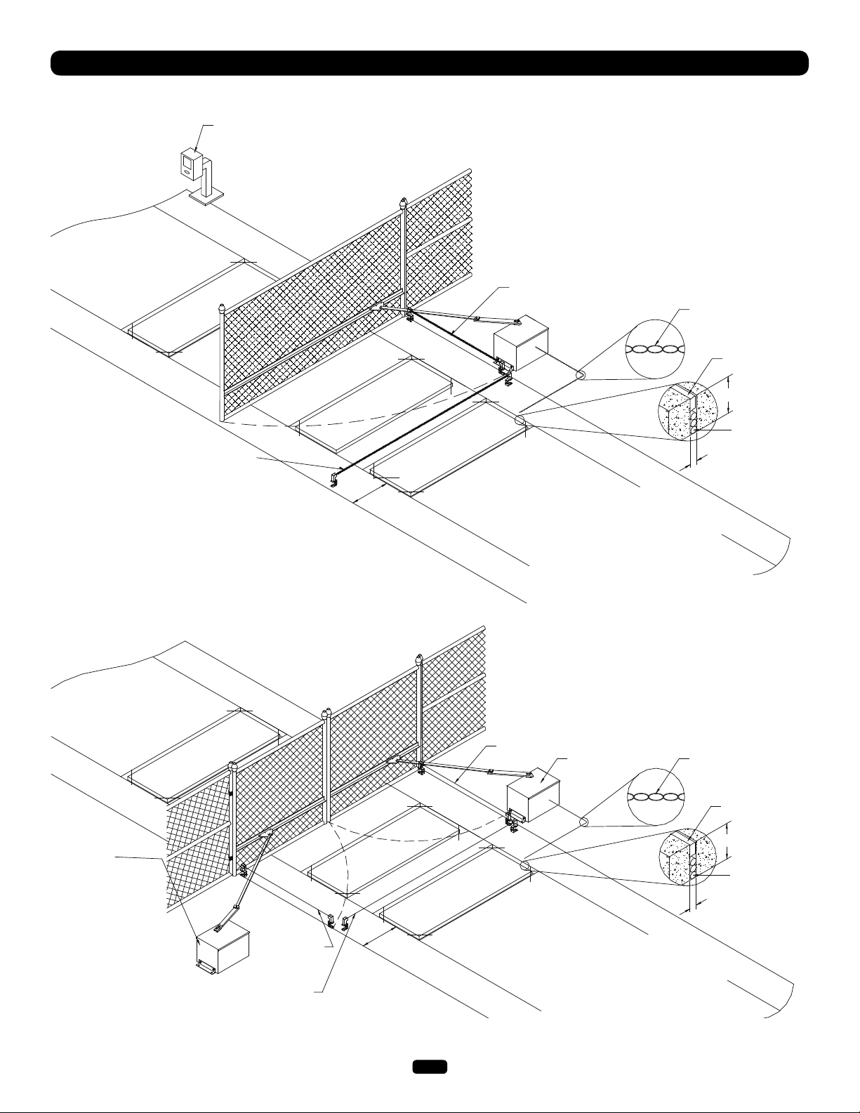
SUGGESTED SAFETY PROTECTION DEVICE LOCATIONS
SWING GATE SYSTEM
STREET
Interrupt (Safety) Loop
Telephone
Entry System
Photo eye for
close cycle
Shadow
Loop
4' (1.2 m)
Typical
Interrupt (Safety) Loop
Photo eye for
open cycle
Run twisted wire*
from loop to
operator
Seal Loops*
1-1/2" (37 mm)
Loop Wire* Layer
1/4" (6 mm) or larger
depending on loop wire
size
COMPLEX
OR
PARKING LOT
DUAL SWING GATE SYSTEM
STREET
Interrupt (Safety)
Loop
Gate 1
Photo eye for
open cycle
Photo eye for
close cycle
Shadow
Loop
4' (1.2 m)
Typical
Interrupt (Safety)
Loop
Photo eye for
open cycle
Gate 2
PARKING LOT
Run twisted wire*
from loop to
operator
Seal Loops*
1-1/2" (37 mm)
Loop Wire* Layer
1/4" (6 mm) or larger
depending on loop wire
size
COMPLEX
OR
* REFER TO LOOP MANUFACTURER’S INSTRUCTIONS FOR DETAILED INSTALLATION & LOOP WIRING INSTRUCTIONS.
6

SAFETY INSTALLATION INFORMATION
1. Vehicular gate systems provide convenience and security. Gate systems are comprised of many component parts. The gate
operator is only one component. Each gate system is specifically designed for an individual application.
2. Gate operating system designers, installers and users must take into account the possible hazards associated with each individual
application. Improperly designed, installed or maintained systems can create risks for the user as well as the bystander. Gate
systems design and installation must reduce public exposure to potential hazards.
3. A gate operator can create high levels of force in its function as a component part of a gate system. Therefore, safety features must
be incorporated into every design. Specific safety features include:
• Gate Edges • Guards for Exposed Rollers • Photoelectric Sensors
• Screen Mesh • Vertical Posts • Instructional and Precautionary Signage
4. Install the gate operator only when:
a. The operator is appropriate for the construction and the usage class of the gate.
b. All openings of a horizontal slide gate are guarded or screened from the bottom of the gate to a minimum of 4' (1.2 m) above
the ground to prevent a 2 1/4" (6 cm) diameter sphere from passing through the openings anywhere in the gate, and in that
portion of the adjacent fence that the gate covers in the open position.
c. All exposed pinch points are eliminated or guarded, and guarding is supplied for exposed rollers.
5. The operator is intended for installation only on gates used for vehicles. Pedestrians must be supplied with a separate access
opening. The pedestrian access opening shall be designed to promote pedestrian usage. Locate the gate such that persons will not
come in contact with the vehicular gate during the entire path of travel of the vehicular gate.
6. The gate must be installed in a location so that enough clearance is supplied between the gate and adjacent structures when
opening and closing to reduce the risk of entrapment. Swinging gates shall not open into public access areas.
7. The gate must be properly installed and work freely in both directions prior to the installation of the gate operator.
8 Controls intended for user activation must be located at least six feet (6') away from any moving part of the gate and where the
user is prevented from reaching over, under, around or through the gate to operate the controls. Outdoor or easily accessible
controls shall have a security feature to prevent unauthorized use.
9. The Stop and/or Reset (if provided separately) must be located in the line-of-sight of the gate. Activation of the reset control shall
not cause the operator to start.
10. A minimum of two (2) WARNING SIGNS shall be installed, one on each side of the gate where easily visible.
11. For a gate operator utilizing a non-contact sensor:
a. Reference owner’s manual regarding placement of non-contact sensor for each type of application.
b. Care shall be exercised to reduce the risk of nuisance tripping, such as when a vehicle trips the sensor while the gate is
still moving.
c. One or more non-contact sensors shall be located where the risk of entrapment or obstruction exists, such as the perimeter
reachable by a moving gate or barrier.
12. For a gate operator utilizing a contact sensor such as an edge sensor:
a. One or more contact sensors shall be located where the risk of entrapment or obstruction exists, such as at the leading edge,
trailing edge and post mounted both inside and outside of a vehicular horizontal slide gate.
b. One or more contact sensors shall be located at the bottom edge of a vehicular vertical lift gate.
c. A hard wired contact sensor shall be located and its wiring arranged so the communication between the sensor and the gate
operator is not subject to mechanical damage.
d. A wireless contact sensor such as the one that transmits radio frequency (RF) signals to the gate operator for entrapment
protection functions shall be located where the transmission of the signals are not obstructed or impeded by building structures,
natural landscaping or similar obstruction. A wireless contact sensor shall function under the intended end-use conditions.
e. One or more contact sensors shall be located on the inside and outside leading edge of a swing gate. Additionally, if the bottom
edge of a swing gate is greater than 6" (152 mm) above the ground at any point in its arc of travel, one or more contact sensors
shall be located on the bottom edge.
f. One or more contact sensors shall be located at the bottom edge of a vertical barrier (arm).
7
GATE CONSTRUCTION INFORMATION
Vehicular gates should be installed in accordance with ASTM F2200: Standard Specification for Automated Vehicular Gate Construction.
For a copy, contact ASTM directly at 610-832-9585 or www.astm.org.
1. GENERAL REQUIREMENTS
1.1 Gates shall be constructed in accordance with the
provisions given for the appropriate gate type listed, refer
to ASTM F2200 for additional gate types.
1.2 Gates shall be designed, constructed and installed to not
fall over more than 45 degrees from the vertical plane,
when a gate is detached from the supporting hardware.
1.3 Gates shall have smooth bottom edges, with vertical
bottom edged protrusions not exceeding 0.50 inches (12.7
mm) when other than the exceptions listed in ASTM
F2200.
1.4 The minimum height for barbed tape shall not be less than
8 feet (2.44 m) above grade and for barbed wire shall not
be less than 6 feet (1.83 m) above grade.
1.5 An existing gate latch shall be disabled when a manually
operated gate is retrofitted with a powered gate operator.
1.6 A gate latch shall not be installed on an automatically
operated gate.
1.7 Protrusions shall not be permitted on any gate, refer to
ASTM F2200 for Exceptions.
1.8 Gates shall be designed, constructed and installed such
that their movement shall not be initiated by gravity when
an automatic operator is disconnected.
1.9 A pedestrian gate shall not be incorporated into a vehicular
gate panel or that portion of the adjacent fence that the
gate covers in the open position.
3.1.4 Positive stops shall be required to limit travel to the
designed fully open and fully closed positions. These stops
shall be installed at either the top of the gate, or at the
bottom of the gate where such stops shall horizontally or
vertically project no more than is required to perform their
intended function.
3.1.5 All gates shall be designed with sufficient lateral stability to
assure that the gate will enter a receiver guide, refer to
ASTM F2200 for panel types.
3.2 The following provisions shall apply to Class IV vehicular
horizontal slide gates:
3.2.1 All weight bearing exposed rollers 8 feet (2.44 m), or less,
above grade shall be guarded or covered.
3.2.2 Positive stops shall be required to limit travel to the
designed fully open and fully closed positions. These stops
shall be installed at either the top of the gate, or at the
bottom of the gate where such stops shall horizontally or
vertically project no more than is required to perform their
intended function.
2. SPECIFIC APPLICATIONS
2.1 Any non-automated gate that is to be automated shall be
upgraded to conform to the provisions of this specification.
2.2 This specification shall not apply to gates generally used
for pedestrian access and to vehicular gates not to be
automated.
2.3 Any existing automated gate, when the operator requires
replacement, shall be upgraded to conform to the
provisions of this specification in effect at that time.
3. VEHICULAR HORIZONTAL SLIDE GATES
3.1 The following provisions shall apply to Class I, Class II and
Class III vehicular horizontal slide gates:
3.1.1 All weight bearing exposed rollers 8 feet (2.44 m), or less,
above grade shall be guarded or covered.
3.1.2 All openings located between 48 inches (1.22 m) and 72
inches (1.83 m) above grade shall be designed, guarded or
screened to prevent a 4 inch
(102 mm) diameter sphere from passing through the
openings anywhere in the gate, and in that portion of the
adjacent fence that covers in the open position.
3.1.3 A gap, measured in the horizontal plane parallel to the
roadway, between a fixed stationary object nearest the
roadway, (such as a gate support post) and the gate frame
when the gate is in either the fully open position or the fully
closed position, shall not exceed 2-1/4 inches (57 mm),
refer to ASTM F2200 for Exception.
4. VEHICULAR HORIZONTAL SWING GATES
4.1 The following provisions shall apply to Class 1, Class II and
Class III vehicular horizontal swing gates:
4.1.1 Gates shall be designed, constructed and installed so as
not to create an entrapment area between the gate and the
supporting structure or other fixed object when the gate
moves toward the fully open position, subject to the
provisions in the 4.1.1.1 and 4.1.1.2.
4.1.1.1 The width of an object (such as a wall, pillar or column)
covered by a swing gate when in the open position shall
not exceed 4 inches (102 mm), measured from the
centerline of the pivot point of the gate, refer to ASTM
F2200 for exception.
4.1.1.2 Except for the zone specified in Section 4.1.1.1, the
distance between a fixed object such as a wall, pillar or
column, and a swing gate when in the open position shall
not be less than 16 inches (406 mm), refer to ASTM F2200
for exception.
4.2 Class IV vehicular horizontal swing gates shall be designed,
constructed and installed in accordance with security
related parameters specific to the application in question.
8
Moving Gate Can Cause
Injury or Death
KEEP CLEAR! Gate may move at any
time without prior warning.
Do not let children operate the gate or
play in the gate area.
This entrance is for vehicles only
Pedestrians must use separate entrance
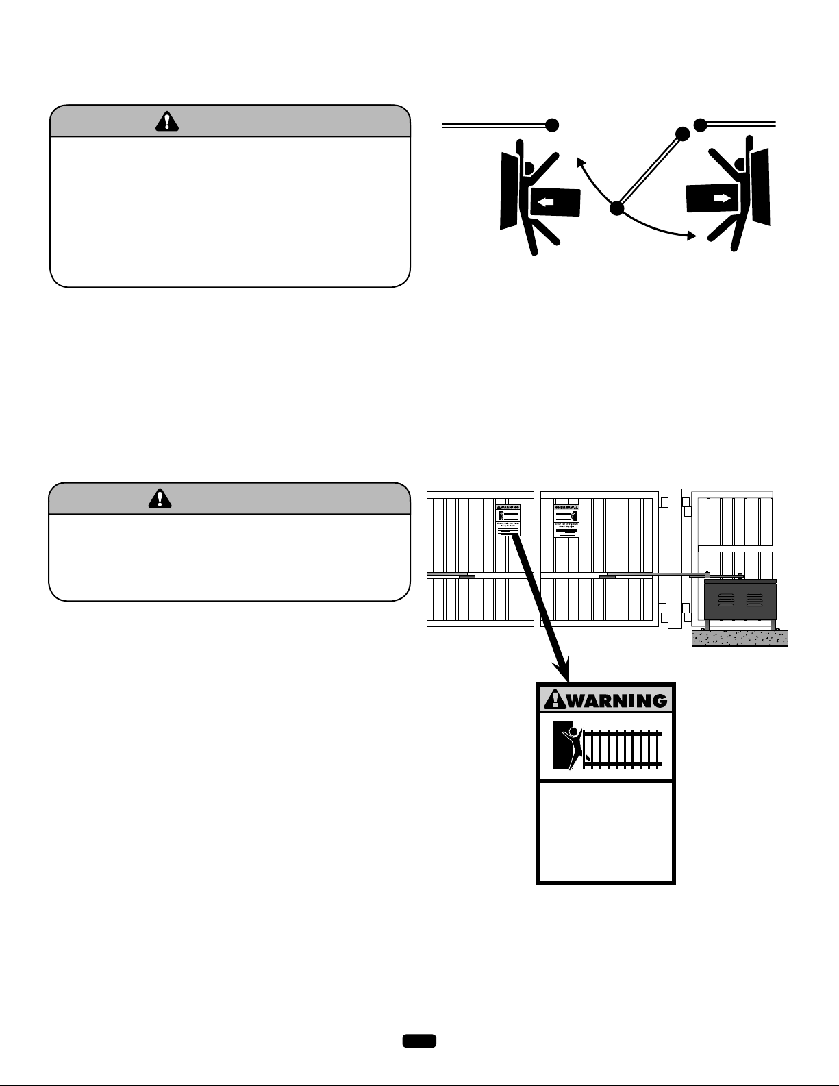
SAFETY PRECAUTIONS FOR SWING AND
WARNING WARNING
WARNING
WARNING WARNING
WARNING
ORNAMENTAL "GRILL TYPE GATES"
To prevent SERIOUS INJURY or DEATH from a moving gate:
• Entrapment protection devices MUST be installed to protect
anyone who may come near a moving gate.
• Locate entrapment protection devices to protect in BOTH the
open and close gate cycles.
• Locate entrapment protection devices to protect between
moving gate and RIGID objects, such as posts.
• A swinging gate shall NOT open into public access ways.
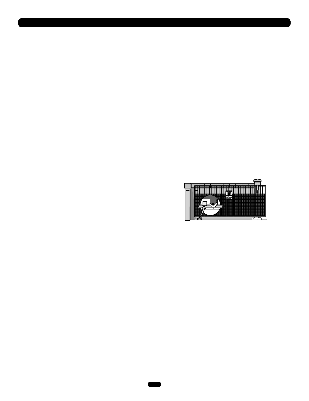
WARNING SIGN PLACEMENT
To prevent SERIOUS INJURY or DEATH from a moving gate:
• Install warning signs on EACH side of gate in PLAIN VIEW.
• Permanently secure each warning sign in a suitable manner
using fastening holes.
9
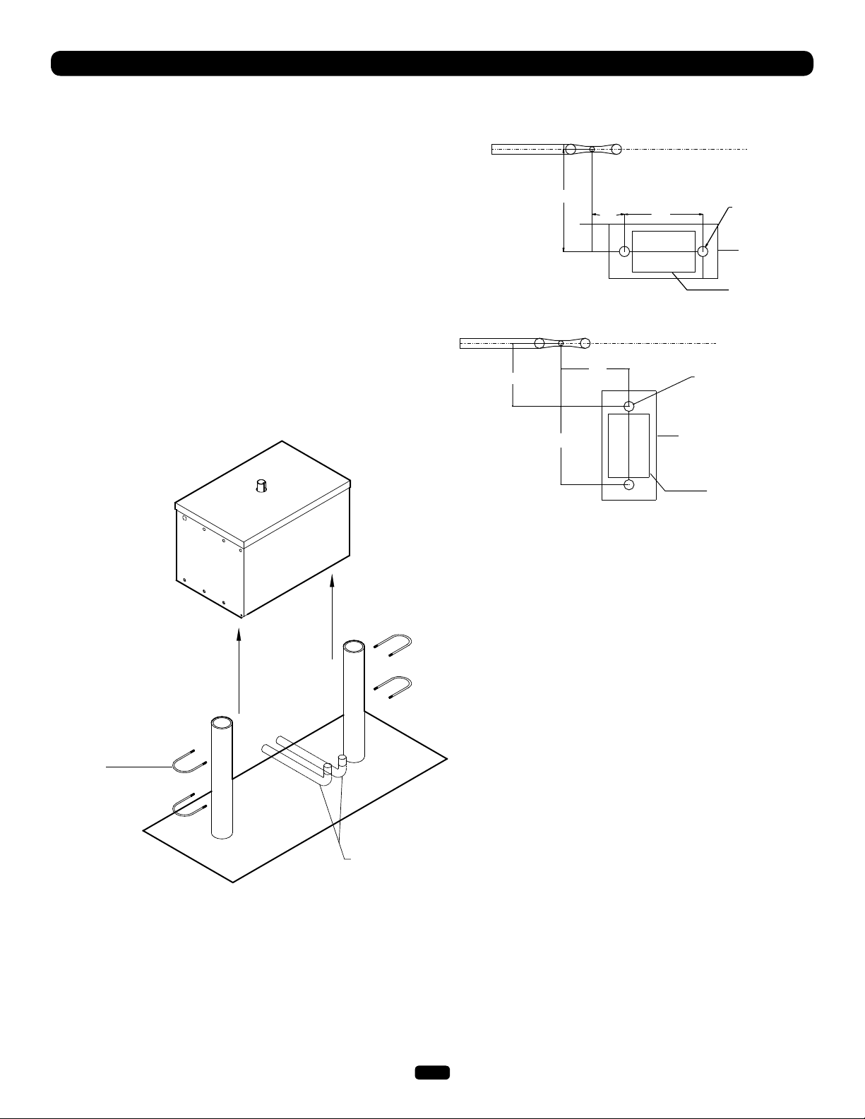
INSTALLATION
POST MOUNTING (SW470)
1. Locate and anchor two posts made of 3" (7.6 cm) outer
diameter heavy walled pipe. Posts should be parallel and
square to the gate.
IMPORTANT NOTE: The distance between mounting posts and
the relative location of the operator to the gate and fence is
critical.
2. Locate electrical conduit, as required, prior to pouring concrete.
3. Set mounting post and electrical conduit in place (Figure 2).
Knockouts for 3" pipe clamps (not supplied) are provided in the
operator.
Figure 2
Figure 1
18.5"
30"
9.5"
Parallel Mount
20"
23"
Fence
Fence
23"
Concrete pad
16 x 32 minimum
3" O.D. pipe
(2 req’d.)
Concrete pad
16 x 32 minimum
Operator
3" O.D. pipe
(2 req’d.)
Operator
3" U-bolt
(4 required)
Perpendicular Mount
Power and control wiring should
be run in separate conduit
10
c
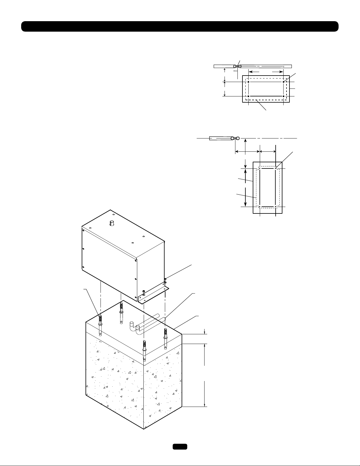
INSTALLATION
PAD MOUNTING (SW470)
1. Layout the concrete pad (Figure 1).
IMPORTANT NOTE: The relative location of the operator to the
fence and the gate is critical. Be sure that the measurements for
operator mounting are taken from the centerline of the fence and
of the gate hinge.
2. Locate electrical conduit, as required, prior to pouring concrete.
3. Pour concrete pad.
4. Bolt the (2) pad mount brackets to the bottom of the operator
with the hardware provided.
5. Secure the operator to the concrete pad. It is very important
that the operator be level and square to the gate.
Figure 2
Figure 1
24"
8"
Gate
Concrete pad
18"x34" min.
Profile of
Operator
SW470
Perpendicular
Hinge Pin
9-3/4"
Parallel Mount
18-3/4"
22-1/2"
22-1/2"
Operator
Centerline
8"6"
Fence
1/2" Redhead
(4 required.)
Concrete pad 18"x34" min.
8"16"1/2" Redhead
(4 required)
1/2" red head bolts or
anchors (4 required)
Perpendicular Mount
Using suitable hardware secure
operator to L-bolts
Power and control wiring should be
run in separate conduit
Concrete Pad
2" to 4" above grade
Depth required by
local codes or below
frost line
11
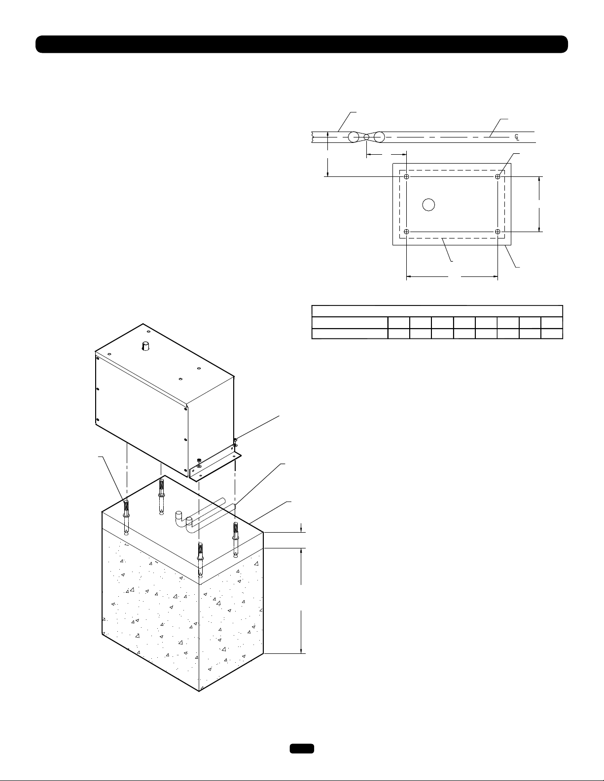
INSTALLATION
PAD MOUNTING (SW490)
1. Measure the gate length and select appropriate “P” dimension
from the gate installation table.
2. Layout the concrete pad as detailed in Figure 1.
IMPORTANT NOTE: The relative location of the operator to the
fence and the gate is critical. Be sure that the measurements for
operator mounting are taken from the centerline of the fence and
of the gate hinge.
3. Locate electrical conduit, as required, prior to pouring concrete.
4. Pour concrete pad.
5. Bolt the (2) pad mount brackets to the bottom of the operator
with the hardware provided (Install the operator so that the
output shaft is on the side closest to the gate).
6. Secure the operator to the pad. It is very important that the
operator be level and square to the gate.
Figure 2
Figure 1
P
SW490 GATE OPERATOR INSTALLATION TABLE
GATE LENGTH (FEET)
P DIMENSION IN INCHES
Gate
Fence
5"
Output
Shaft
Operator
28"
8-9 10-11 12-13 14-15 16-17 18-19 20-21 22
21.9 25.3 28.8 32.3 35.7 39.2 42.7 46.1
1/2" Redhead
(4 Required)
Concrete Pad
18" x 34" min.
8"
1/2" red head bolts or
anchors (4 required)
Using suitable hardware secure
operator to L-bolts
Power and control wiring should be
run in separate conduit
Concrete Pad
2" to 4" above grade
Depth required by
local codes or below
frost line
12
 Loading...