

Page 1
Programming Instructions
Sentex
Sentex
SentexSentex
systems
01-16169F1
Gate Operator Models
SLMAX & SW2200
Doc 01-16169
Rev B
Page 2

2
SLMAX/SW2200 Programming Instructions
Contents
SLMAX/SW2200 Programming Controls __________________________ 3
Viewing the Gate’s Current Status ________________________________ 3
Programming the Single Button Functions__________________________ 4
Setting the Gate Open/Close Limits _______________________________ 6
Setting the Gate Operator Speed__________________________________ 7
Setting the Deceleration Limits ___________________________________ 9
Setting the Entrapment Level ____________________________________ 9
Setting the Loop Detector_______________________________________ 10
Enabling/Disabling the Operator Warning ________________________ 11
Setting the Gate’s Timer to Close ________________________________ 11
Setting the Electric Lock Delay __________________________________ 12
Factory Default Settings________________________________________ 13
NOTE: For information about the Troubleshooting screen, see the SW2200
Installation Manual and SLMAX Installation Manual.
IMPORTANT!
READ ME FIRST
The SLMAX and SW2200 Gate Operators come pre-programmed with default
settings. When first installed, you will not need to program each feature. In
fact, you may want to review the system’s default settings (see Factory Default
Settings, p. 13) before you start programming. You may or may not want different
settings than those already defined.
Doc 01-16169
Rev B
Page 3
LiftMaster
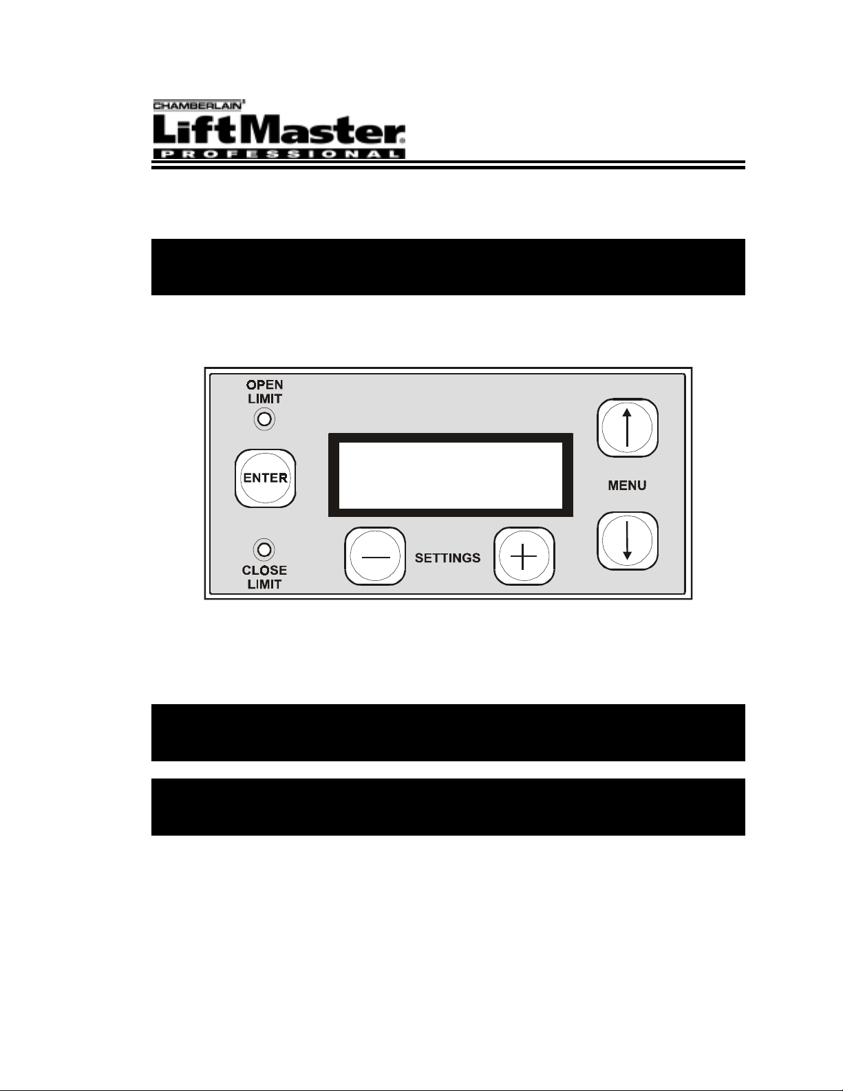
SLMAX/SW2200 Programming Controls
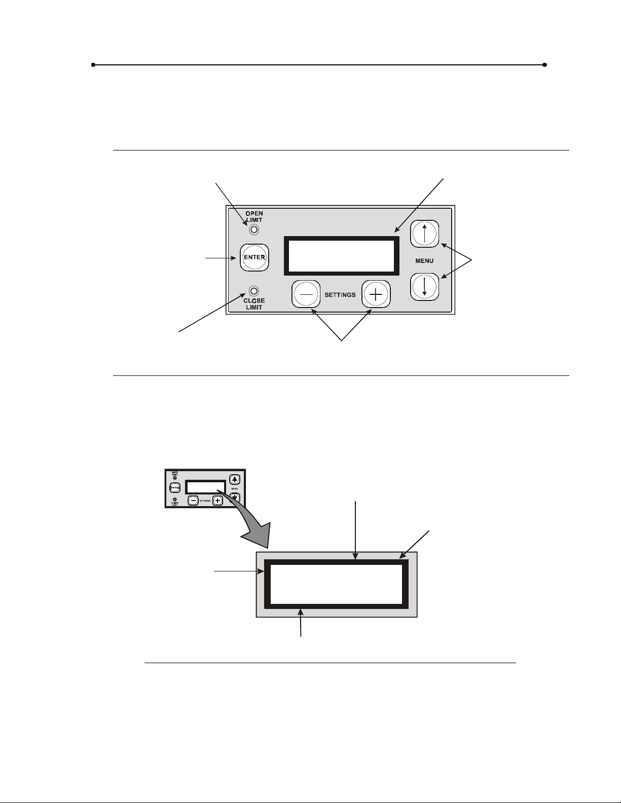
Programming occurs on a 5-button, 2-LED membrane switch located on top of the
control box (see Figure 1). Programming instructions appear on a 2-row, 16-character
LCD screen.
The OPEN LIMIT LED
flashes during Open Limit
programming.
LCD SCREEN
3
systems
01-16169F2
Press the ENTER button
to select a program or
save program settings.
The CLOSE LIMIT LED
flashes during Close Limit
programming.
Sentex
Sentex
SentexSentex
Use the SETTINGS
buttons to set the program
settings.
Figure 1: Programming Controls
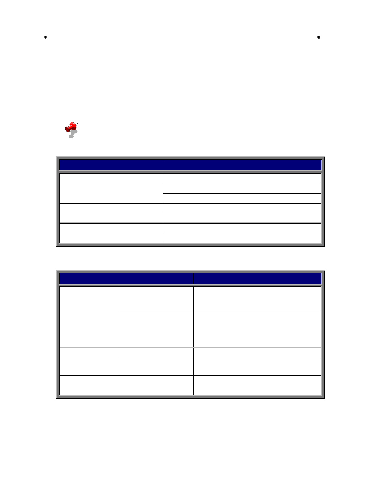
Viewing the Gate’s Current Status
The system’s default screen displays the gate’s current status. Refer to Figure 2.
systems
Sentex
Sentex
SentexSentex
Gate Type: SINGLE
or MASTER/SLAVE
Microprocessor
Revision
Use the MENU Buttons
to scroll up/down the
programming menu.
Gate Power:
AC or UPS
AC SINGL 3.0
CLOSED
01-161 69F3
Gate Status:
OPEN or CLOSED
Figure 2: Status Screen
Doc 01-16169
Rev B
Page 4
4
SLMAX/SW2200 Programming Instructions
Programming the Single Button Functions
FACTORY DEFAULT: OPENING = STOP, NO TIMER RESET
CLOSING = (None—button has no effect)
MID-STOP = MID -STOP OPEN
The Single Button (connected at the J8 input connector) programming feature allows
you to configure the single button function (i.e., how the gate reacts after you press the
single button). You may program the single button function to perform the actions
outlined in Table 2.
NOTE: There is no factory default setting when the gate is “CLOSING”. When
the gate closes, the single button will have no effect. However, you may
program the “STOP” or “REVERSE” options (see below).
Selectable options include the following:
GATE CONDITIONS PROGRAMMABLE FUNCTIONS POSSIBLE
STOP
OPENING
CLOSING
AT MID-STOP
OPEN ONLY
STOP, NO TMR RST
STOP
REVERSE
MID-STOP OPE N
MID-STOP REVERSE
Table 1: Programmable Options
If the gate is . . . and you select . . . the gate will . . .
Stop. If “TIMER TO CLOSE” is activated
OPENING
CLOSING
AT MID-STOP
STOP
OPEN ONLY
STOP, NO TMR RST
STOP Stop.
REVERSE
MID-STOP OPEN Travel to the open position.
MID-STOP REVERSE Close if the gate was previously opening.
Table 2: Single Button Functions
(see p. 11), the gate closes after timer
elapses.
Continue to open—does not allow you to
stop gate using single button.
Stop. If activated, “TIMER TO CLOSE”
function will not occur.
Stop and then reverse to the open
position.
Doc 01-16169
Rev B
Page 5

Set the Single Button Function
To set the single button function, follow the steps below:
PROCEDURES DISPLAY PROMPT
LiftMaster
5
1 Pressing the MENU buttons (!"), locate the
SINGLE BUTTON option and press ENTER.
2 For the first setting, press (–) or (+) to select the
desired option and press ENTER to save.
Options: Stop—Stop, No Tmr Rst—Open Only
3 For the second setting, press (–) or (+) to select
the desired option and press ENTER to save.
Options: Stop—Reverse
4 For the third setting, press (–) or (+) to select the
desired option and press ENTER to save.
Options: Open—Reverse
SINGLE BUTTON
OPENING
(OPTION)
CLOSING
(OPTION)
MIDSTOP
(OPTION)
Doc 01-16169
Rev B
Page 6

6
SLMAX/SW2200 Programming Instructions
Setting the Gate Open/Close Limits
NO FACTORY DEFAULT SETTING
This feature allows you to set the gate’s open or close limits without utilizing limit
switches. You are essentially setting the operator so it knows how far to open and
close its gate.
NOTE: After a power outage or operator gate disengagement, the operator will
retain its limit settings.
Also, to stop the gate while setting the limits, release the (+) or (-) buttons.
Press these buttons to correct any over-travel.
To set the Gate Open/Close Limits, follow these steps:
PROCEDURES DISPLAY PROMPT
1 Pressing the MENU buttons (!"), locate the LIMITS
MENU option and press ENTER.
2 At the RESET LIMITS (+) prompt, press (+) to start
programming.
3 Press (+) to continue programming. (+) TO CONTINUE
4 Press and hold (+) or (–) to close the gate. SET CLOSE LIMIT
5 When the gate reaches the desired closed limit position,
release (+) or (-) and press ENTER.
The Close Limit LED will blink to indicate that the close
limit position is accepted but not yet stored in the
memory.
6 Press and hold (+) or (–) to open the gate. SET OPEN LIMIT
7 When the gate reaches the desired open limit position,
release (+) and (-) and press ENTER.
The Open Limit LED will blink to indicate that the open
limit position is accepted but not yet stored in the
memory.
LIMI TS MEN U
ENTER TO CHANGE
RESET LIMITS (+)
(–) TO EXIT
(+/–) TO POSI TION
SET CLOSE LIMIT
ENTER TO SET
(+/–) TO POSI TION
SET OPEN LIMIT
ENTER TO SET
8 Press ENTER to test the gate’s limits .
The gate will automatically close, open, and finally close
to the programmed close/open limit positions.
Press any key to stop the gate during the limit test.
9 When the operator finishes the test, the Close Limit and
Open Limit LEDs will stay lit to indicate that the limit
positions are now stored in the system’s memory.
Doc 01-16169
Rev B
PRESS ENTER TO
TEST LIMITS
Page 7

LiftMaster
Setting the Gate Operator Speed
This feature allows you to change the speed of the gate. Please note that max speed
(normal gate speed) and min speed (decelerated gate speed) have their own minimum
and maximum range.
For the SW2200, Table 4 provides speed settings based on the total amount of time it
takes the gate to fully open or close.
Refer to Table 3 and Table 4 to select proper gate speeds for the SLMAX and SW2200:
7
MAX GATE
SPEED
(INCHES/SEC)
12” 170 8.8” 120 (Max.)
11” 157 8” 110
10” 144 7” 97
9” 130 6” 83
8” 117 5” 70
7” 104 4.2 60 (Min.)
6.8” 100 (Min.) --- ---
GATE OPEN OR CLOSE
PROGRAMMED
SETTING
Table 3: Max and Min Gate Speeds for the SLMAX
TIME ( S EC)
14 220 (Max.)
15 200
16 190
17 170
MIN GATE
SPEED
(INCHES/SEC)
PROGRAMMED SETTING
PROGRAMMED
SETTING
18 155
19 145
20 130
21 120
22 115
23 110
24 105
25 100 (Min.)
Table 4: Max Gate Speed for the SW2200
Doc 01-16169
Rev B
Page 8

8
SLMAX/SW2200 Programming Instructions
NOTE: The open/close time settings in Table 4 are valid if:
(1) You install the gate with the gate dimensions recommended in the
installation manual.
(2) T he Open and Close Deceleration Limits are programmed at the
minimum (100) setting.
(3) T he Min Gate Speed is programmed to 120.
Factory Defaults
SLMAX = MAX SPEED: 220
MIN SPEED: 60
SW2200 = MAX SPEED: 220
MIN SPEED: 60
Setting the Gate Speed
To set the operator speed, follow the steps below:
-and-
-and-
PROCEDURES DISPLAY PROMPT
1 Pressing the MENU buttons (!"), locate the
OPERATOR SPEED option and press ENTER.
2 Press (–) or (+) to set the maximum gate speed.
NOTE: Maximum speed refers to the speed of
the gate during opening or closing.
3 Press ENTER to save.
4 Press (–) or (+) to set the minimum gate speed.
NOTE: Minimum speed refers to the speed of
the gate when it slows down prior to reaching the
open or close limit.
5 Press ENTER to save.
OPERATOR SPEED
MAX SPEED: (See Table)
(+/–) TO ADJUST
MIN SPEED: (See Table)
(+/–) TO ADJUST
Doc 01-16169
Rev B
Page 9

LiftMaster
Setting the Deceleration Limits
This feature allows you to set the distance during which the gate starts to slow down
prior to stopping at the open or close limit.
Set the Open Deceleration Limit
FACTORY DEFAULT = MEDIUM
To set the Open Deceleration Limit, follow these steps:
PROCEDURES DISPLAY PROMPT
9
1 Pressing the MENU buttons (!"), locate the
OPEN DECEL LIMIT option and press ENTER.
2 Press (–) or (+) to set the distance.
3 Press ENTER to save.
OPEN DECEL LIMIT
__ __ __ I __ __ __
[LESS MOREΨ
Set the Close Deceleration Limit
FACTORY DEFAULT = MEDIUM
To set the Close Deceleration Limit, follow these steps:
PROCEDURES DISPLAY PROMPT
1 Pressing the MENU buttons (!"), locate the
CLOSE DECEL LIMIT option and press ENTER.
2 Press (–) or (+) to set the distance.
3 Press ENTER to save.
CLOSE DECEL LIMIT
__ __ __ I __ __ __
[LESS MOREΨ
Setting the Entrapment Level
FACTORY DEFAULT = 25
This feature allows you to set the gate’s sensitivity to an obstruction.
0 = Most Sensitive
99 = Least Sensitive
To set the entrapment level, follow these steps:
PROCEDURES DISPLAY PROMPT
1 Pressing the MENU buttons (!"), locate the
ENTRAPMENT option and press ENTER.
2 Press (–) or (+) to set the entrapment level. ENTRAPMENT LEVEL
3 Press ENTER to save.
ENTRAPMENT
SET LEVEL: (0-99)
Doc 01-16169
Rev B
Page 10

10
SLMAX/SW2200 Programming Instructions
Setting the Loop Detector
FACTORY DEFAULT = LOOP INPUT A: OPEN LOOP
LOOP INPUT B: SAFETY LOOP
LOOP INPUT C: SHADOW LOOP
This feature allows you to program the desired loop function using the J4 inputs (A, B,
and C). Before setting the loop detector, check which loop types are connected to the
J4 inputs.
EXAMPLE: Input A may be connected to an Open Loop Detector. If so, set
Input A on J4 to Open Loop.
Loop types include:
Open Loops
Safety Loops
Shadow Loops (may be used in swing gate systems—not slide gates).
To set the Loop Detectors, follow these steps:
PROCEDURES DISPLAY PROMPT
1 Pressing the MENU buttons (!"), locate the
LOOP DETECTORS option and press ENTER.
2 Assign a loop type to Input A. Press (–) or (+) to
select the desired option.
3 Press ENTER to save.
4 Assign a loop type to Input B. Press (–) or (+) to
select the desired option.
5 Press ENTER to save.
6 Assign a loop type to Input C. Press (–) or (+) to
select the desired option.
7 Press ENTER to save.
NOTE: Setting multiple Loop Inputs to the same
option (e.g., Open, Safety, or Shadow) will not
adversely affect the operator’s loop function.
LOOP DETECTORS
LOOP INPUT A
(OPTION)
LOOP INPUT B
(OPTION)
LOOP INPUT C
(OPTION)
Doc 01-16169
Rev B
Page 11

LiftMaster
Enabling/Disabling the Operator Warning
FACTORY DEFAULT = OFF
This feature allows you to enable or disable the operator alarm that warns people with
beeps when the gate is moving.
NOTE: If you enable the operator warning, and when the gate is prompted to
open, the alarm will sound immediately, but the gate will start opening after a
programmed number of seconds (1-9).
To enable or disable the operator warning, follow the steps below:
PROCEDURES DISPLAY PROMPT
11
1 Pressing the MENU buttons (!"), locate the
OPERATOR WARNING option and press ENTER.
2 Press (–) or (+) to enable or disable the warning
alarm.
OFF = Alarm does not sound off during gate
movement.
Gate has no delay.
1-9 = Alarm sounds off during gate movement.
Gate will start after set number of seconds
(1-9).
3 Press ENTER to save.
OPERATOR WARN ING
OPERATOR WARN ING
DELAY START: (0-9)
Setting the Gate’s Timer to Close
FACTORY DEFAULT = OFF
This feature allows you to set the time (in seconds) the gate stays open prior to closing
automatically.
To set the gate’s Timer to Close, follow these steps:
PROCEDURES DISPLAY PROMPT
1 Pressing the MENU buttons (!"), locate the
TIMER TO CLOSE option and press ENTER.
2 Press (–) or (+) to enable or disable the timer to
close function.
OFF = Gate does not close automatically.
1-120 = Gate will close automatically after a
programmed number of seconds (1-120).
3 Press ENTER to save.
TIMER TO CLOSE
OPERATOR WARN ING
DELAY START: (1-120)
Doc 01-16169
Rev B
Page 12

12
SLMAX/SW2200 Programming Instructions
Setting the Electric Lock Delay
FACTORY SETTING = OFF
All gates installed with a maglock (connected to the JP6 connector/input) may have the
electric lock delay function programmed into the system. This delays the gate from
opening for a programmed number of seconds (1-10) when the operator is prompted to
open. After the delay, the operator will de-energize the maglock (allowing the gate to
unlock) and open the gate.
To set the Electric Lock Delay, follow these steps:
PROCEDURES DISPLAY PROMPT
1 Pressing the MENU buttons (!"), locate the
ELECTRIC LOCK option and press ENTER.
2 Press (–) or (+) to select the delay time.
OFF = No delay.
1-10 = Gate will open after set number of
seconds (1-10).
3 Press ENTER to save.
ELECTRIC LOCK
ELECTRIC LOCK
DELAY START: (1-10)
Doc 01-16169
Rev B
Page 13

LiftMaster
Factory Default Settings
The SLMAX and SW2200 come programmed with factory default settings so that you
won’t have to program each step when an operator is first installed. If the operator has
been installed recently, review the factory default settings (Table 5) and decide which
settings you’d like to change.
You may also reset the existing settings to their default parameters. To do this, follow
the steps below:
PROCEDURES DISPLAY PROMPT
13
1 Pressing the MENU buttons (!"), locate
FACTORY DEFAULTS and press ENTER.
2 Press (+) to restore th e factory default se ttings. RESTORE DEFAU LTS
PROGRA MMIN G OPTION DEFAULT SETTING
OPENING = STOP, NO TIMER RESET
SINGLE BUTTON
SLMAX/SW2200
OPERATOR SPEED
OPEN DECELERATION LIMIT MEDIUM
CLOSE DECELERATION LIMIT MEDIUM
ENTRAPMENT LEVEL 25
LOOP DETECTORS
CLOSING = (None—button has no effect)
MID-STOP = MID-STOP OPEN
MAXIMUM SPEED: 220
MINIMUM SPEED: 60
LOOP INPUT A: OPEN LOOP
LOOP INPUT B: SAFETY LOOP
LOOP INPUT C: SHADOW LOOP
FACTORY DEFAULTS
–NO +YES
OPERATOR WARN ING OFF
TIMER TO CLOSE OFF
ELECTRIC LOCK OFF
Table 5: Default Settings
Doc 01-16169
Rev B
Page 14

COPYRIGHT 2001
ALL RIGHTS RESERVED
This document is protected by copyright and may not be copied or adapted without the prior written
consent of LiftMaster. This documentation contains information proprietary to LiftMaster and such
information may not be distributed without the prior written consent of LiftMaster. The software and
firmware included in the LiftMaster product as they relate to this documentation are also protected by
copyright and contain information proprietary to LiftMaster.
FOR TECHNICAL SUPPORT
Call our toll free numbers:
(800) 323-2276
(800) 998-9197
Installation and service information is
available six days a week.
TO ORDER REPAIR PARTS
Call our toll free numbers:
(800) 528-2806
(800) 998-9197
Prepare to provide the following
information when ordering repair parts:
! Part Number
! Part Name
! Model Number
 Loading...