

Page 1
Spectrum Software for Windows
Software Rev. 2.0 and Up
Spectrum
Spectrum DI
User’s Guide
Doc 6001197, Rev D
Page 2

Contents
2
Contents
Introduction: SVWin Software Basics _________________________________________________ 4
Chapter 1: Installing SVWin_______________________________________________________ 5
About this Manual ______________________________________________________________________ 5
System Requirements ____________________________________________________________________ 5
Installing SVWin _______________________________________________________________________ 6
SVWin “Help” Aids _____________________________________________________________________ 7
Chapter 2: Starting SVWin ________________________________________________________ 8
Starting SVWin_________________________________________________________________________ 8
Passwords _____________________________________________________________________________ 9
SVWin Unit Setup Overview _____________________________________________________________ 11
The Menu Bar_________________________________________________________________________ 12
The Main Menu _______________________________________________________________________ 13
Chapter 3: Modem Configuration__________________________________________________ 14
Configuring Your Modem _______________________________________________________________ 14
Modem Connection Trouble______________________________________________________________ 15
Chapter 4: New Unit Setup _______________________________________________________ 16
Adding a New Unit Definition ____________________________________________________________ 16
Connecting to a Unit____________________________________________________________________ 17
Receiving Data from a New Unit __________________________________________________________ 20
Directory Code Size Mismatch____________________________________________________________ 21
Chapter 5: Editing a Unit ________________________________________________________ 22
Selecting an SVWin Main Database________________________________________________________ 22
Selecting a Unit to Edit__________________________________________________________________ 23
Editing a Unit Configuration _____________________________________________________________ 24
Work On Unit (Reference) _______________________________________________________________ 25
Chapter 6: Managing Directory Codes ______________________________________________ 26
Adding Directory Codes_________________________________________________________________ 26
Resolving Differences in Directory Code Length _____________________________________________ 27
Editing Directory Codes _________________________________________________________________ 28
Deleting a Directory Code _______________________________________________________________ 28
Sorting or Deleting Groups of Directory Codes _______________________________________________ 29
Doc 6001197, Rev D
Page 3

Contents
3
Chapter 7: Managing Entry Codes _________________________________________________ 30
Adding Entry Codes____________________________________________________________________ 30
Editing an Entry Code __________________________________________________________________ 31
Deleting an Entry Code _________________________________________________________________ 32
Sorting or Deleting Groups of Entry Codes__________________________________________________ 32
Chapter 8: Sending Data to a Unit _________________________________________________ 33
About Sending Changes_________________________________________________________________ 33
Sending All to a Unit ___________________________________________________________________ 34
Sending Changes to a Unit_______________________________________________________________ 34
Chapter 9: Relay Control_________________________________________________________ 35
Control Panel for Unit Reference__________________________________________________________ 35
Relay Control Options __________________________________________________________________ 36
Chapter 10: Scheduling Communication with Units ____________________________________ 37
About Scheduling Communication with Units _______________________________________________ 37
Scheduling to Send Changes to All Units ___________________________________________________ 38
Scheduling to Receive All Data from a Unit _________________________________________________ 39
Directory or Entry Code Conflict__________________________________________________________ 40
Scheduling to Send All Data to a Unit ______________________________________________________ 40
Scheduling to Send Changes to a Unit ______________________________________________________ 41
Chapter 11: Printing _____________________________________________________________ 42
Printing the Unit Information Report_______________________________________________________ 42
Printing the Directory Insert______________________________________________________________ 43
Chapter 12: Upgrading Spectrum Unit Memory _______________________________________ 45
About Upgrading Spectrum Unit Memory___________________________________________________ 45
Preparing SVWin for Spectrum Memory Upgrade ____________________________________________ 45
After Installation of the New Microchip ____________________________________________________ 46
Doc 6001197, Rev D
Page 4

Introduction: SVWin Software Basics
4
Introduction: SVWin Software Basics
Spectrum software for Windows (SVWin) offers the ability to program and maintain Spectrum
units with a –101 or -301 board. SVWin has the following features:
EASY INSTALLATION
FAST STARTUP
CONVENIENCE
DATA CONTROL
SCHEDULING
RELAY CONTROL
The SVWin software guides you quickly and easily through the
installation procedure.
Enter data without first connecting with the unit, so as soon as the
unit is installed, you’re ready to download the unit information, send
new data, and go.
Program unit configurations, entry codes, directory codes and
telephone numbers from a remote location.
Control data precedence when receiving data.
Maintain and edit all data offline, and then schedule uploading or
downloading at a convenient time.
Control unit functions directly. Connect to the unit, select the control
panel, and you can cycle, latch or release relays.
Doc 6001197, Rev D
Page 5
Chapter 1: Installing SVWin
This chapter will cover . . .
Information about this Manual
Page 5
Chapter 1: Installing SVWin
5
System Requirements
Installing SVWin
SVWin “Help” Aids
Page 5
Page 6
Page 7
About this Manual
The procedures in this manual assume that you have already read the manuals for your
telephone entry system (Spectrum).
System Requirements
Windows-based software offers many advantages in terms of usability and versatility, but
requires a computer configuration powerful enough for it to work effectively. While you may be
able to run SVWin on older, less powerful computers, it will run very slowly and with greater
chance of failure. For this reason we strongly recommend using at least the minimum computer
configuration. To use SVWin software, the following items are required:
A Sentex Spectrum with -101 or -301 Board connected to a telephone line.
An IBM PC-Compatible computer running Windows 95 (full version) or higher.
Internet Explorer version 4.01 (service pack 2) or later (5.0 or later recommended).
Internet Explorer is provided on the CD for your convenience.
MINIMUM RECOMMENDED REQUIRED
Pentium 166 Processor
32 MB of RAM
200 MB hard disk free
Pentium II Processor
128 MB of RAM
300 MB hard disk free
SVWin System Requirements
Hayes-compatible modem
connected via a COM port
CD ROM
Mouse
IMPORTANT NOTE
SVWin stores information about its settings in the Windows Registry. If you need to change this
information, Sentex dealers should call Sentex Systems Technical Support for assistance.
Doc 6001197, Rev D
Page 6

Chapter 1: Installing SVWin
6
Installing SVWin
In order for SVWIN to operate properly, it must be installed onto the computer hard disk drive.
SVWIN cannot be executed directly from the CD.
SVWin is compatible with the following operating systems: Windows 95 (full version), 98, ME,
NT, and 2000.
Windows 95 Users: You must have Y2K Update installed on your machine.
Windows 98 (before Second Edition) Users: You must have Y2K Update 2 installed
on your machine – does not apply to Windows 98, Second Edition.
Windows NT 4 Users: You must have Service Pack 5 (or greater) installed on your
machine.
Windows NT/2000 Users: You must have administrator privileges to install SVWin.
NOTE: SVWin will not run in Windows 3.1 or 3.11. You must be running Windows 95 (full
version) or above to run the application.
To install SVWIN Software, perform the following steps:
1 Start Windows.
2 Place the SVWin CD in the CD ROM drive. SVWin will automatically start the
installation process; follow the on-screen prompts. If the installation process does not
automatically start, continue with step 3.
3 From the taskbar, select the Start Button, point to Settings, then click on Control
Panel.
4 From the Control Panel window, double-click on Add/Remove Programs.
5 From the Add/Remove Programs screen, under the Install/Uninstall tab, click Install.
6 Follow the on-screen prompts.
NOTES:
SVWin may prompt you to reboot your machine a few times during the
installation process. This is required by Microsoft. If after each reboot SVWin
does not automatically continue with the installation process, double-click on
the Setup.exe file in the SVWin software installation CD.
Once SVWin is installed, you may enter unit data to the SVWin database (e.g.,
adding unit definitions) without being connected to a unit. If you do this, you
should perform a Receive Merge after the first time you connect (refer to page
17) so the data from the Spectrum Memory merges with the data in the SVWin
database.
Doc 6001197, Rev D
Page 7

Chapter 1: Installing SVWin 7
WINDOWS NT/2000 USERS ONLY
If there are multiple SVWin users, you must perform these last two steps after SVWin has
completed its installation:
Provide shared privileges for the entire SVWin subdirectory (and any other directory that
will store the databases) AND
Grant “Full Control” permission for each SVWin user to each subdirectory storing the
SVWin databases.
SVWin “Help” Aids
HTML help - Press F1 on your keyboard to open the SVWin Help file. Use the help to answer
questions about SVWin or to learn more about it.
Balloon help - Balloon help is available on most screens, providing a brief identifying statement
describing most buttons and many screen features. The “balloon” is a small yellow box that
appears near the item it describes.
Status bar - The status bar is located at the bottom of most screens and provides screen
information or helpful suggestions.
Doc 6001197, Rev D
Page 8
Chapter 2: Starting SVWin
8
Chapter 2: Starting SVWin
This chapter will cover . . .
Starting SVWin
Page 8
Passwords
SVWin Unit Setup Overview
The Menu Bar
The Main Menu
Page 9
Page 11
Page 12
Page 13
Starting SVWin
1 Click on START.
2 From the fly-up START menu, select PROGRAMS.
3 From the fly-out PROGRAMS menu, select Sentex Applications.
4 From the Sentex Applications menu, select SVWin.
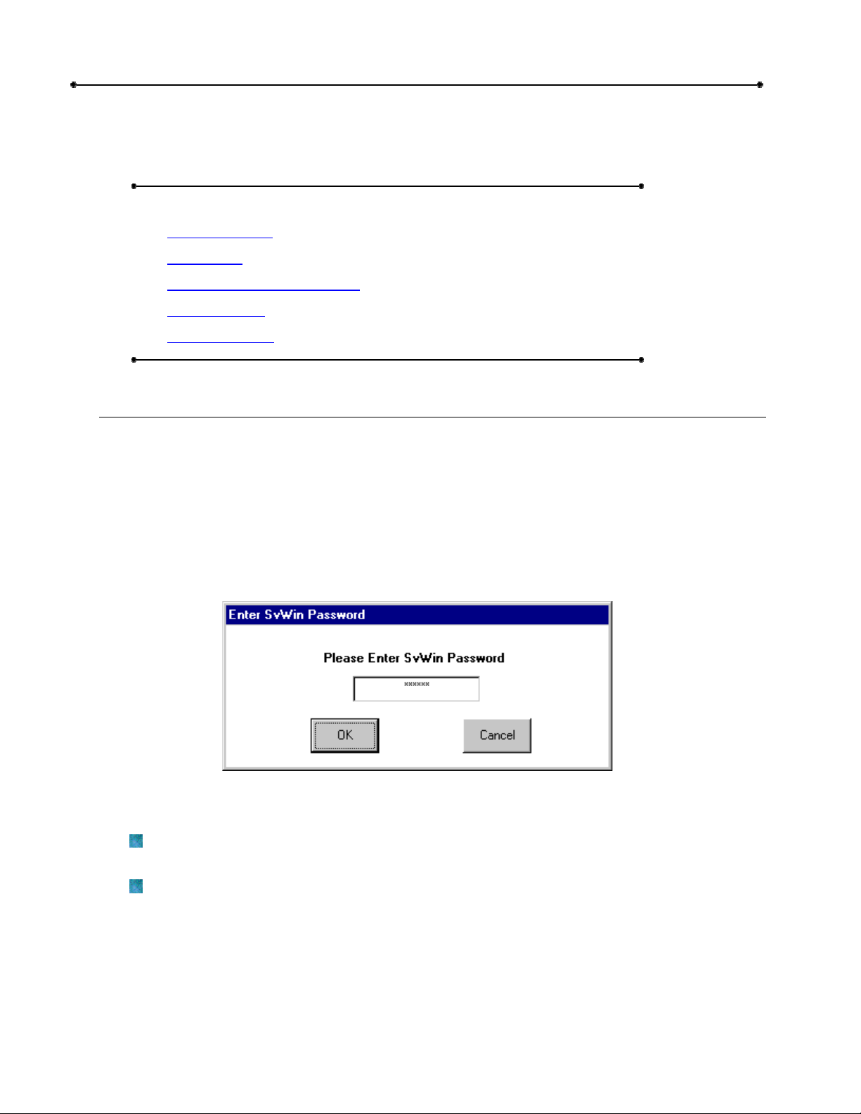
5 If the Enter SVWin Password screen appears, enter the password and click OK. If you
do not know your password, check with the system administrator or the person who
assigned it.
NOTES:
Sentex Applications is the default name of the program group and will appear unless you
change the program group name at installation.
To create a shortcut to SVWin, drag the SVWin EXE file icon onto the desktop (see
Windows User Guide for details).
Doc 6001197, Rev D
Figure 1: Enter SVWin Password Screen
Page 9
Chapter 2: Starting SVWin 9
Passwords
ABOUT UNIT AND SVWIN PASSWORDS
There are two types of passwords used in SVWin:
Unit Passwords
SVWin Passwords
Unit Passwords are required when connecting to a unit and must be 6 numeric digits in length.
Unit passwords also add an extra level of security by allowing you to assign selected units to
other SVWin users.
SVWin Passwords are not required and, if used, must be 6 numeric digits in length. SVWin
passwords force SVWin users to enter a password when opening the application.
EDITING A UNIT PASSWORD
Unit passwords are created automatically (default = 000000) when you create a new unit
definition. IMPORTANT: If the unit password in SVWin is different than the unit password at the
unit, then you will not
To edit the password, follow these steps:
be able to connect to the unit.
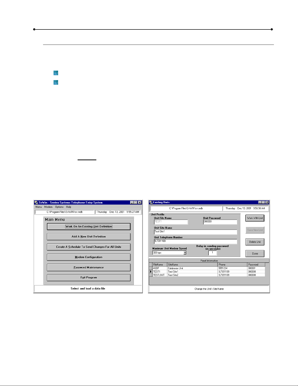
1 From the main menu (see Figure 2), click Work on an Existing Unit Definition.
2 At the Existing Units window (see Figure 3), select the desired unit from the Panel
Information table.
Figure 2: SVWin Main Menu
3 In the Unit Password field, enter the new password. Unit passwords must be six numeric
digits in length.
Figure 3: Existing Units Screen
4 Click Work with Unit.
Doc 6001197, Rev D
Page 10
Chapter 2: Starting SVWin
10
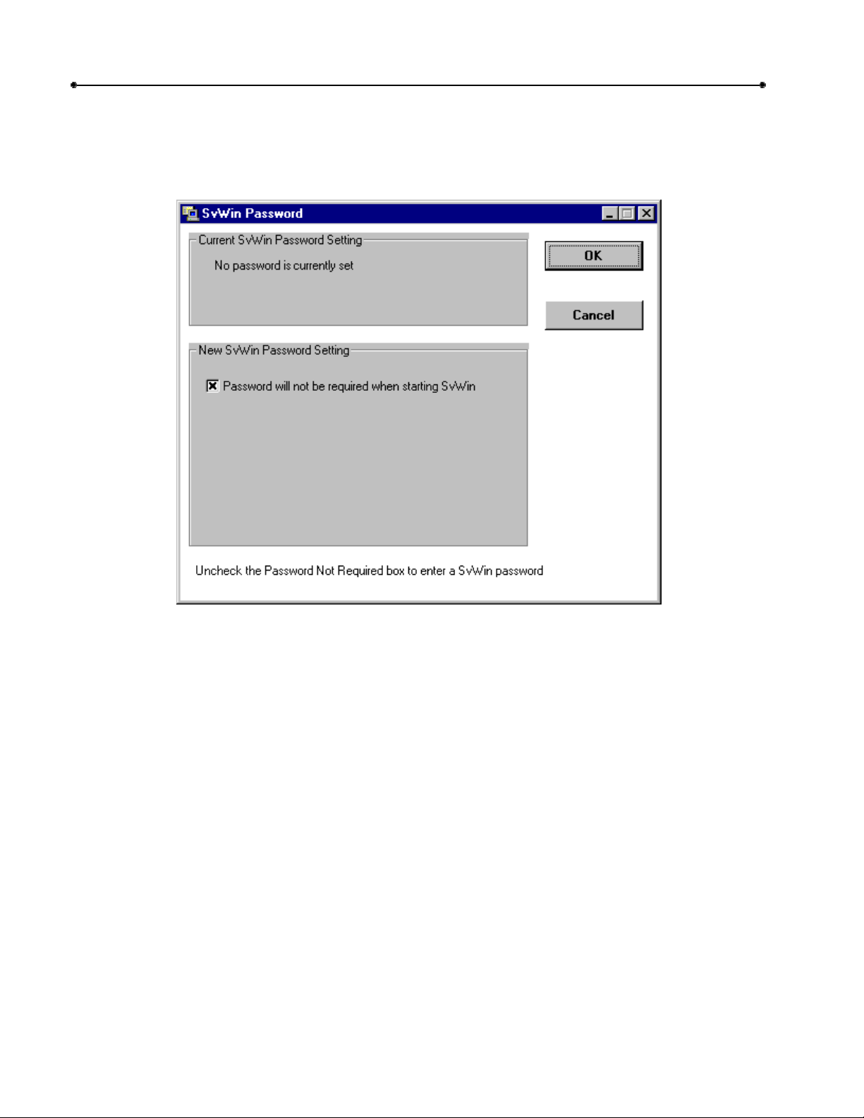
CREATING AN SVWIN PASSWORD
1 From the main menu, click Password Maintenance.
2 From the SVWin Password screen (see Figure 4), disable the Password will not be
required when starting SVWin checkbox.
Figure 4: SVWin Password Screen
3 Enter the new SVWin password. The SVWin password may only be 6 numeric digits in
length.
4 Re-enter the password in the Verify New SVWin Password box.
5 Click OK.
EDITING AN SVWIN PASSWORD
1 From the main menu, click Password Maintenance.
2 From the SVWin Password screen, enter the current SVWin password.
3 To disable the password requirement, click to enable the Password will not be required
when starting SVWin checkbox.
4 Enter the new SVWin password. The SVWin password may only be 6 numeric digits in
length.
5 Re-enter the password in the Verify New SVWin Password box.
6 Click OK.
Doc 6001197, Rev D
Page 11

Chapter 2: Starting SVWin 11
SVWin Unit Setup Overview
Because SVWin is capable of so much, units can require extensive setup if all SVWin functions
will be used. When setting up new units, Sentex recommends that you follow the setup
sequence provided below.
1. SET UP THE MODEM AND PORT:
Enter your modem and port settings (telephone number, etc.) to communicate with your
unit.
2. SET UP THE NEW UNIT:
Create a file for the new unit. Unit files require a unique file name and the unit’s telephone
number. If the unit has not been installed yet, you may edit the factory settings and enter
directory codes, telephone numbers, and entry codes. However, Sentex recommends that
you receive the unit data first (see step 3).
3. RECEIVE UNIT DATA:
Connect to the unit and receive the data entered at the unit during installation.
4. EDIT THE UNIT’S CONFIGURATION:
Edit the factory settings, if required.
5. SEND DATA TO THE UNIT:
If you changed the unit’s configuration, you need to send all the new data to the unit.
6. SET UP THE DIRECTORY CODES:
Enter the directory codes. Directory codes are unique codes with a programmed number of
digits that dial a corresponding telephone number in the building or complex.
7. SET UP THE ENTRY CODES:
Entry codes are unique 4-digit codes that authorized personnel can use to gain access.
8. SEND CHANGES TO THE UNIT:
Send all programming changes made in SVWin to the unit.
9. PRINT THE UNIT REPORTS:
Print reports detailing the unit configuration, directory codes, and entry codes on your
computer’s printer.
10. PRINT THE DIRECTORY:
Print the directory listing of tenants and their directory codes.
Doc 6001197, Rev D
Page 12
Chapter 2: Starting SVWin
12
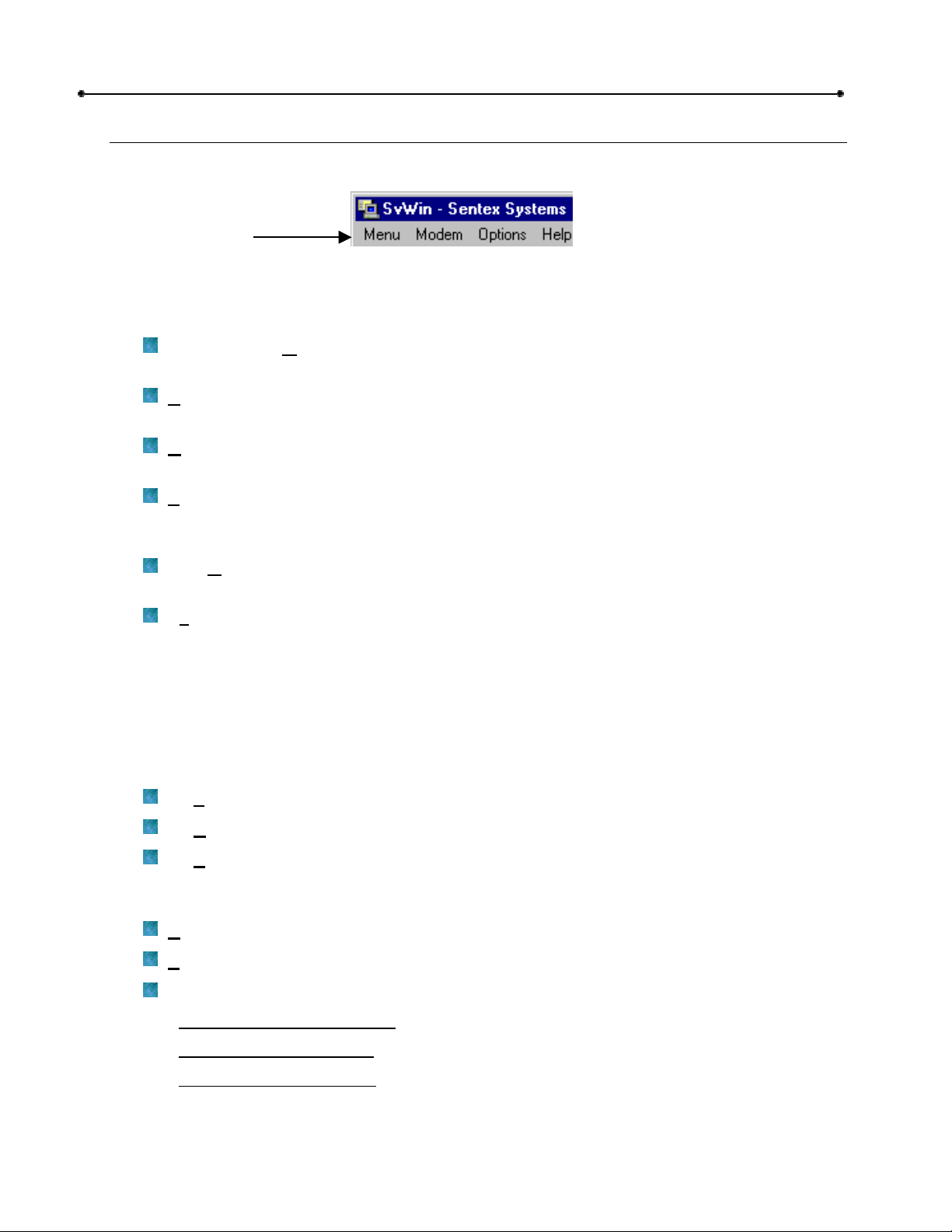
The Menu Bar
The Menu Bar contains four drop-down menus for frequently-used SVWin features.
Menu Bar
Figure 5: The SVWin Menu Bar
MENU
Displays a drop-down menu of unit and database features:
Select SVWin M
Selecting an SVWin Main Database on page 22 for more information.
ew Unit Database: Click to add a new unit to the SVWin database. See Adding a
N
New Unit Definition on page 16 for more information.
pen Unit Database: Click to view or edit SVWin Unit data. See Editing a Unit
O
Configuration on page 24 for more information.
chedule Changes: Click to schedule a time for SVWin to automatically send changes
S
to all units. See Scheduling to Send Changes to All Units on page 38 for more
information.
Passw
password. See Passwords on page 9 for more information.
it: Shuts down SVWin and returns to Windows.
Ex
ord: Opens the SVWin password screen. Allows you to create or edit an SVWin
ain Database: Click to select a different SVWin Main database. See
MODEM
Configure: Allows you to configure your modem settings. See Configuring Your Modem on
page 14 for more information.
OPTIONS
Displays a drop-down menu of optional SVWin features:
Set F
Set Background Color: Allows you to change SVWin's background color.
Set Progress Bar Color: Allows you to change the color of SVWin's progress bar.
oreground Color: Allows you to change SVWin's foreground color.
HELP
elp Topics: Opens the SVWin HTML Help file.
H
bout SVWin: Displays information about your version of SVWin.
A
Technical Support: Offers technical support information and database repair functions.
Obtaining Technical Support
Repair SVWin Databases
Unlock SVWin Databases
* Use only under the guidance of dealer qualified technical support.
: Information about whom to contact for technical support.
*: Analyzes, compacts, and repairs an SVWin database.
*: Unlocks an SVWin database.
Doc 6001197, Rev D
Page 13

Chapter 2: Starting SVWin 13
The Main Menu
The Main Menu has various buttons that link to SVWin’s primary screens.
Work On An Existing Unit Definition: Displays the Existing Units screen, allowing you
to edit an existing unit definition.
Add a New Unit Definition: Displays the Add New Unit screen, allowing you to create a
new unit definition.
Create a Schedule To Send Changes For All Units: Displays the Schedule When To
Send Changes To All Units screen, allowing you to set up a schedule to automatically
send changes to all units.
Modem Configuration: Displays the Modem Setup screen, allowing you to configure
your modem settings.
Password Maintenance: Opens the SVWin Password screen, allowing you to create or
edit an SVWin password.
Exit Program: Exits SVWin.
Doc 6001197, Rev D
Page 14
14
Chapter 3: Modem Configuration
Chapter 3: Modem Configuration
This chapter will cover . . .
Configuring Your Modem
Page 14
Modem Connection Trouble
Page 15
Configuring Your Modem
In order to communicate with your Spectrum unit, you must enter your port and modem settings
in SVWin.
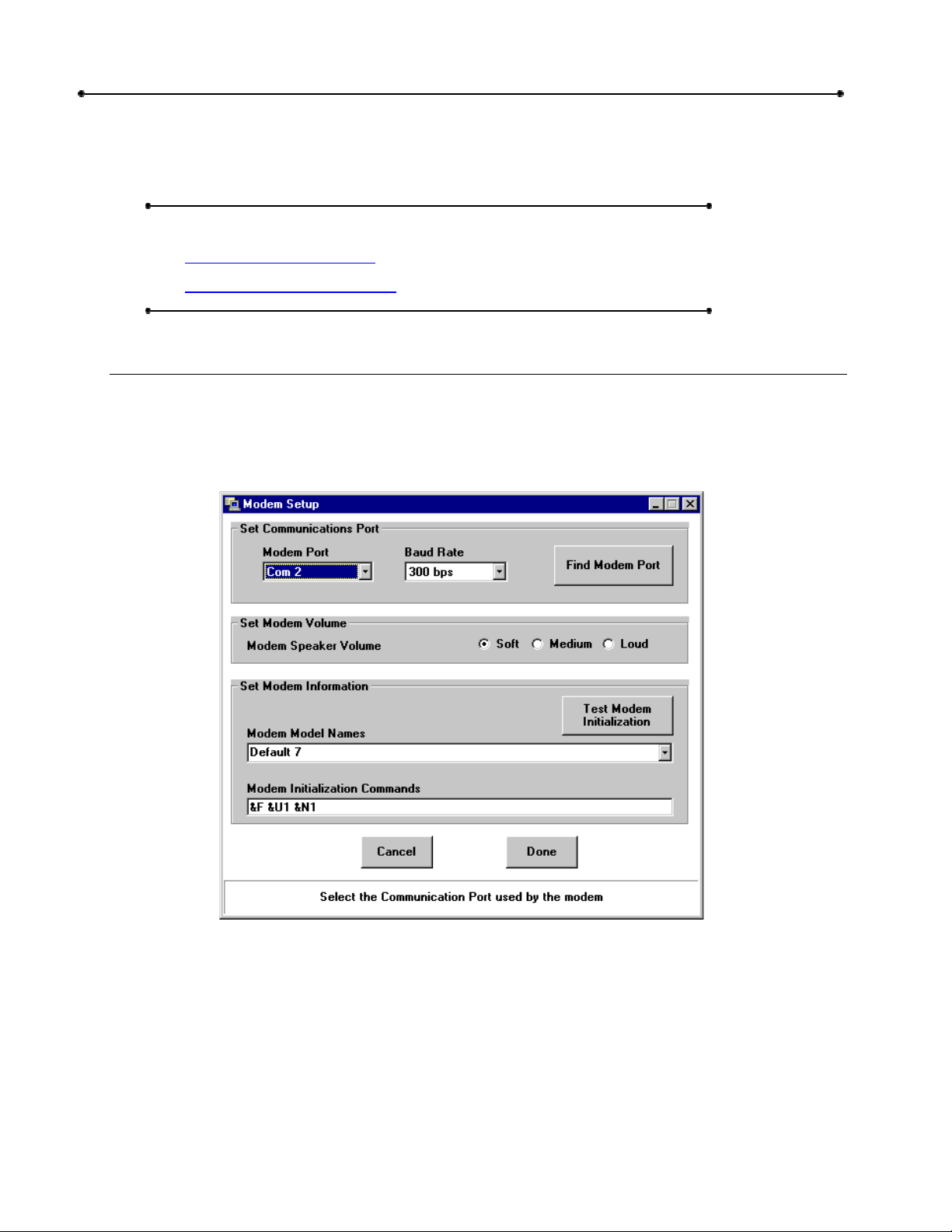
To set the modem, click the Modem Configuration button on the main menu. The Modem
Setup screen will appear (see Figure 6).
1 Find Modem Port: Click the Find Modem Port button. SVWin searches the computer’s
configuration and locates the port to which the modem is connected. When detected,
SVWin displays the port identification in the Modem Port box.
2 Baud Rate: Select your modem’s baud rate (300 or 2400). NOTE: 2400 baud modems
are ONLY supported by Spectrum units with the -301 board.
3 Set Modem Volume: Select the desired Modem Speaker Volume.
Doc 6001197, Rev D
Figure 6: Modem Setup Screen
Page 15

Chapter 3: Modem Configuration
4 Set Modem Information: Select your computer’s modem from the Modem Model Names
drop-down field.
Don’t know your modem type? Check your modem settings in your computer’s control
panel: Click the windows Start button (bottom-left corner), go to Settings, Control
Panel, and double-click Modems.
If your modem type is not a selection in the drop-down field, you may manually
enter the model type and initialization string.
As another option, select a Default value from the drop-down field. If the first
default setting doesn’t work, try other default settings.
As another option, select Auto-Negotiate; this will work for most modern
modems.
5 Test Modem Initialization: Select the Test Modem Initialization button. If the modem
initialization string is acceptable, SVWin responds with the message, “Modem Response
OK” in the status bar. If the modem initialization string is not acceptable, “ERROR”
displays. In the case of an “ERROR”, edit the commands according your modem
instructions and test again.
6 Select the Done button to save your settings and return to the main menu.
PLEASE NOTE: SVWin may not be able to identify the modem. It may be necessary to
modify the initialization commands to make the modem work correctly. To modify the
modem initialization string, it must have the following features:
DTE speed 300 bits per second (with BELL103 protocol) OR
DTE speed 2400 bits per second
No data compression
No error correction
No protocol negotiation
No automatic speed changing
15
NOTE: If you need assistance with your modem, including help with editing the modem
initialization string, contact your computer retailer or modem manufacturer.
Modem Connection Trouble
The vast majority of connection problems are associated with incorrect modem initialization
strings.
If your modem Connection Type is “Timed” (Communicate with Unit screen) and you suspect
that SVWin is sending the unit password too soon, try changing the Delay in sending password
(Existing Units screen).
1 Increase the Delay setting by one second and try connecting to the unit again. The
factory default is zero (0) seconds.
2 Continue increasing the Delay setting by one second, and testing again, until you have
reached 30 seconds.
3 If no Delay settings between 1 and 30 seconds work, contact your dealer for technical
support.
Doc 6001197, Rev D
Page 16

Chapter 4: New Unit Setup
16
Chapter 4: New Unit Setup
This chapter will cover . . .
Adding a New Unit Definition
Page 16
Connecting to a Unit
Receiving Data from a New Unit
Directory Code Size Mismatch
Page 17
Page 20
Page 21
Adding a New Unit Definition
You may add a new unit definition even if your unit has not yet been installed. Follow the
procedures below and then begin adding directory codes (see page 26 for more information).
To add a new unit definition, click the Add a New Unit Definition button on the Main Menu. The
Add New Unit screen will appear (see Figure 7).
1 Unit File Name: Enter a file name for the new unit in the Unit File Name box. The name
can be up to 8 characters long and can include letters, numbers, and punctuation, but not
spaces.
If the file name already exists, you have two options:
Enter a new file name, OR
Use the existing file.
Doc 6001197, Rev D
Figure 7: Add New Unit Screen
Page 17

Chapter 4: New Unit Setup
2 Unit Site Name (Optional): Enter the unit site name in the Unit Site Name box. The site
name can have up to 64 characters, including spaces.
3 Unit Telephone Number: Enter the unit telephone number in the Unit Telephone
Number box.
4 Unit Password: In order for SVWin to connect to the unit, SVWin's unit password must
match the unit password currently at the unit. If you don't know the current unit
password, leave the default value at 000000.
5 Maximum Unit Modem Speed: Select the modem's baud rate (300 or 2400 baud). If
you don't know, refer to your modem's documentation.
6 Delay in sending password (in seconds): When SVWin connects to the unit, it will wait
the number of seconds displayed in this field before it sends the password.
7 Save New Unit: Click this button to save your data. To return to the Main Menu without
saving the data, select the Done button.
If your unit has been installed, we recommend you receive data next. Refer to
page 20.
If your unit has not been installed yet, and you want to begin entering data, begin
adding directory codes (see page 26).
17
Connecting to a Unit
In order to receive or send data to a unit, you must connect to that unit. Access the
Communicate with Unit screen and follow the instructions below. To access the Communicate
with Unit screen (Figure 8), click the Connect to Unit button in the Communication Panel on the
Work On Unit screen.
Figure 8: Communicate with Unit Screen
1 Review and edit, if necessary, the connection settings. Refer to the reference information
below.
2 Click the Connect button.
Doc 6001197, Rev D
Page 18

Chapter 4: New Unit Setup
18
COMMUNICATE WITH UNIT SCREEN REFERENCE
BOX DESCRIPTION
Site Name
Site name displays if it was entered on the Add New Unit screen.
Connection
Telephone
The unit’s telephone number displays.
Number
Unit Password
Connection
Type
Unit password displays.
Automatic (Recommended): After a certain number of rings
(predetermined) and 5 seconds of silence, SVWin will automatically send
the unit password.
Timed: After a certain number of rings (predetermined) and the number of
seconds defined in the Delay in Sending Password box (Existing Units
screen), SVWin will automatically send the unit password.
Manual: After the modem dials the phone number, you must manually
send the unit password during initial communication.
Baud Rate
Allows you to select the modem's baud rate (300 or 2400).
BUTTONS – SEND/RECEIVE/PURGE DATA
Receive All Click to receive all data from the Spectrum Memory to your local SVWin
Unit database. SVWin will Purge Changes before receiving all data from
the Spectrum Memory. Any changes you made to the SVWin Unit
database since the last time you performed a Receive All or Send All will
be replaced by the information from the Spectrum Memory.
Receive Merge Click to merge data from the Spectrum Memory with the SVWin Unit
database. If a matching code is detected, the data at the SVWin Unit
database will have priority.
Send Changes All changes entered into the SVWin Unit database since the last send
command will be sent to the Spectrum Memory. Once your Spectrum
Memory and SVWin Unit databases are current, to save time, Send
Changes after all subsequent edits to the SVWin Unit database.
Purge Changes
After purging changes, you must perform one of the following commands:
Receive All (Recommended): If you purge changes and Receive All:
Any changes you made to the SVWin Unit database since the last
time you performed a Receive All or Send All will be deleted.
Your SVWin Unit database will receive all data from the Spectrum
Memory.
Send All: If you purge changes and Send All . . .
Any changes you made to the SVWin Unit database since the last
time you performed a Receive All or Send All will NOT be deleted.
All the Spectrum Memory data will be deleted and replaced with
the data from the SVWin Unit database.
Send All All the Spectrum Memory data will be deleted and replaced with the data
from the SVWin Unit database. Use if a Spectrum unit is replaced, you
want to reconfigure the unit, or if the unit and SVWin have mismatched
data and the data from the SVWin Unit database is correct.
Doc 6001197, Rev D
Page 19

Chapter 4: New Unit Setup
BUTTONS
Connect
Disconnect
Modem
Settings
Send Password
Click to connect SVWin to the unit.
Click to disconnect from the unit.
Click to edit your modem settings; allows you to access the Modem Setup
screen.
If Manual in the Connection Type box is chosen, click to send unit
password.
Control Panel
Click to display the Control Panel for Unit screen.
Cancel Click to cancel “Send All”, “Receive All’, or “Send Changes”. Clicking
Cancel also exits the screen without saving unit data.
Done Click to save unit data, exit the screen, and return to Work On Unit screen.
Clicking Done also cancels “Send All”, “Receive All’, or “Send Changes”.
STATUS INDICATORS
Connect Status
Box
Status Report
Box
Reports connection status and displays modem activity lights.
Reports communication activity.
Status Bar Helpful description of various functions (bottom of screen). Activated by
mouse movement.
Tx/Rx Lights that activate when SVWin transmits (Tx) and receives (Rx) data
to/from the unit.
DATA TRANSFER ERROR
A data transfer error may occur while sending or receiving data to/from the unit (e.g., from phone
line disconnection), thereby causing the data to scramble.
If this type of error occurs, you must Send All (if you were sending data) or Receive All (if you
were receiving data).
19
Doc 6001197, Rev D
Page 20

Chapter 4: New Unit Setup
20
Receiving Data from a New Unit
Before doing any other work on a new or upgraded unit, we recommend that you Receive All
data from the unit. This procedure may take anywhere from a few minutes to an hour. No other
functions are available during this procedure.
IMPORTANT NOTE: If you have entered data to the SVWin database prior to connecting
to the new unit, you should perform a Receive Merge (substitute for step 7 below). The
Receive Merge function will merge the data from the Spectrum Memory with the SVWin
database. If you Receive All, all the data in your SVWin database will be deleted and
replaced with the data from the Spectrum Memory.
1 From the Main Menu, select Work On An Existing Unit Definition. The Existing Units
screen will be displayed.
2 The Panel Information grid (bottom of screen) contains a list of existing units. Select the
row of your new unit.
3 Click Work With Unit. The Work On Unit screen will be displayed.
4 From the Work On Unit screen in the Communication panel, select Connect to Unit.
The Communicate with Unit screen is displayed.
The unit's telephone number is automatically displayed in the Connection Telephone
Number box. If the site name was entered on the Add New Unit screen, the site name
appears in the Site Name box.
5 Select the Connection Type:
Automatic/Timed: The unit password is automatically sent during initial
communication.
Manual: The unit password is not automatically sent during initial communication.
6 Select Connect. SVWin will connect to the unit. When you are connected, the message
"Connected to Unit" appears in the Connect Status box.
7 In the Send/Receive Data box, select the Receive All button. SVWin will receive all the
data entered into the Spectrum Memory during installation. This process may take
anywhere from a few minutes to over an hour. Do not attempt to use other SVWin
functions while SVWin is receiving data from the unit.
IMPORTANT NOTE: If the directory code length received from the unit is different than
the directory code length specified in SVWin, SVWin will display a message stating that
there is a mismatch in the directory code size. See Directory Code Size Mismatch on
page 21 for more information.
8 When SVWin is finished receiving data, you will see a message in the lower box. Select
the Disconnect button. The message "Not Connected" will be displayed in the Connect
Status box.
9 Select Done. You will be returned to the Work On Unit Screen. You are now ready to
make changes to the unit.
Doc 6001197, Rev D
Page 21

Chapter 4: New Unit Setup
Directory Code Size Mismatch
If a directory code size conflict occurs:
SVWin will display a message stating that there is a mismatch in the directory code size
after receiving data from the unit (see Figure 9).
The SVWin Unit database will use the larger of the two lengths.
21
Example:
with three digits, but the current code length is set to “2”, the code length setting will
be automatically changed to “3”.
If a directory code with less digits is received into a database with a larger code size
setting, the smaller code will change to accommodate the larger code length setting. A
leading zero “0” will be added for each missing digit.
Example:
set to “3” and it receives directory code “12”, the code will change to “012”.
If the SVWin Unit database or Spectrum Memory receive directory codes
If the SVWin Unit database or Spectrum Memory directory code length is
Figure 9: Directory Code Size Mismatch Alert
Doc 6001197, Rev D
Page 22

Chapter 5: Editing a Unit
22
Chapter 5: Editing a Unit
This chapter will cover . . .
Selecting an SVWin Main Database
Page 22
Selecting a Unit to Edit
Editing a Unit Configuration
Work On Unit (Reference)
Page 23
Page 24
Page 25
Selecting an SVWin Main Database
SVWin allows you to work with any SVWin database to which your computer can access. This
feature provides the following benefits:
Allows you to place the main database (database name.mdb) on a network so multiple
users can write to it.
Allows you to revert to a backup copy in case the current, active database becomes
corrupt.
To select a new main database, perform the following steps:
1 At the Main Menu, select Menu --> Select SVWin M
2 At the Spectrum Main Database File Name screen (Figure 10), locate the desired
database and click O
pen.
ain Database.
Doc 6001197, Rev D
Figure 10: Spectrum Vista Data File Name Screen
Page 23

Chapter 5: Editing a Unit 23
Selecting a Unit to Edit
NOTE: Before doing any other work on a new or upgraded unit, we recommend that you
Receive All settings from the unit. Refer to Receiving Data from a New Unit on page 20.
From the Main Menu, select the Work On An Existing Unit Definition button. The Existing
Units screen will appear (Figure 11).
Figure 11: Existing Units Screen
Unit Profile: Information for the unit you select appears at the upper section of the
screen.
Panel Information: Information for all existing unit files is listed in this grid.
1 Select Site: In the Panel Information grid, click on the row of the site that you wish to
edit. The file data displays in the Unit Profile box.
2 Edit the fields in the Unit Profile box, if necessary.
3 Click the Work with Unit button to edit more unit data.
Doc 6001197, Rev D
Page 24

Chapter 5: Editing a Unit
24
Editing a Unit Configuration
In the Add/Edit panel, click the Configuration button. The Edit System Configuration screen will
appear (Figure 12).
Figure 12: Edit System Configuration Screen
OPTION DESCRIPTION INPUT FACTORY SETTING
Talk Time (In
Seconds)
Relay 1 Activation
Time
Relay 2 Activation
Time
Rings Before
Answer
Maximum Number Of
Keypad Errors
Number of Directory
Code Digits
Dialing Type
PBX Digit
Firmware
Information
(For your information) FID Supplied upon connection to the unit
Maximum number of
seconds for visitor call
Number of seconds relay 1
remains active
Number of seconds relay 2
remains active
Number of rings before the
system answers
Number of wrong entries
before unit stops accepting
codes for 3 minutes.
1 - 4 digits. Factory Set = 3
Tone or Pulse Factory Set = Tone
PBX digit to dial for outside line Factory Set = Disabled
Firmware Version Supplied upon connection to the unit
15 - 250 60 seconds
1 - 99 10 seconds
1 - 99 10 seconds
0 - 9 rings
0 = disable
0 - 9 errors
0 = disables this
feature
2 rings
2 keypad errors
Doc 6001197, Rev D
Page 25

Chapter 5: Editing a Unit 25
Work On Unit (Reference)
NOTE: Before doing any other work on a new or upgraded unit, we recommend that you
Receive All settings from the unit. Refer to Receiving Data from a New Unit on page 20.
Figure 13: Work On Unit Reference
FILE DATA BAR
Displays the site name; alerts you to whether changes have been sent to the unit;
shows the number of changes made since the last updates were sent to the unit; and
shows the computer's date and time.
INFORMATION PANEL
Print Unit Data: Provides the ability to print the following reports: Configuration, Directory
Codes, and Entry Codes.
Directory Insert: Provides the ability to export the directory codes into a text file (.txt) for
printing the directory insert.
Help: Provides on-line help.
ADD/EDIT PANEL
Configuration: Provides the ability to edit the system configuration.
Directory Codes: Provides the ability to add, edit, or erase directory codes.
Entry Codes: Provides the ability to add, edit, or erase entry codes.
COMMUNICATION PANEL
Connect To Unit: Provides the ability to connect to the unit.
Modem: Click to view or edit the modem settings.
Schedule: Provides the ability to schedule the time to send and/or receive unit data.
Doc 6001197, Rev D
Page 26

Chapter 6: Managing Directory Codes
26
Chapter 6: Managing Directory Codes
Directory codes are unique codes that dial a corresponding telephone number in the
building. When a visitor wishes to contact a resident, the visitor types in the directory code.
The resident is able to talk to the visitor by telephone and determine whether or
not to permit the visitor entry.
The directory code can be 1 to 4 digits long.
This chapter will cover . . .
Adding Directory Codes
Page 26
Resolving Differences in Directory Code Length
Editing Directory Codes
Deleting a Directory Code
Sorting or Deleting Groups of Directory Codes
Page 28
Page 28
Page 27
Page 29
Adding Directory Codes
From the Work On Unit screen – Add/Edit Panel - select Directory Codes. The Add/Edit
Directory Codes and Telephone Numbers screen will appear.
Figure 14: Add/Edit Directory Codes and Telephone Numbers
If the Directory Code Conflict dialogue box appears, see Directory or Entry Code Conflict on
page 40.
Doc 6001197, Rev D
Page 27

Chapter 6: Managing Directory Codes 27
1 Dir. Code: Enter the new directory code in this box.
2 Telephone Number: Enter the telephone number that the unit will call when a visitor
enters the directory code.
3 Name (optional): Select the Name box and enter a name. This entry can be up to 31
characters in length and can include letters, numbers, and punctuation marks.
4 Save: Select the Save button to save the directory code.
5 To enter more directory codes, repeat steps 1 through 5.
6 Done: Select the Done button when all directory codes are entered. You will be returned
to the Work On Unit screen.
IMPORTANT NOTE: The Capacity Used box shows the number of codes already
assigned. The Remaining box shows the number of codes available. If the number of
directory codes entered exceeds the capacity, the Remaining number will turn red. You
will not be allowed to send data to the units until the extra codes have been deleted.
Resolving Differences in Directory Code Length
If you manually change a directory code length (refer to Editing a Unit Configuration on page
24) to a shorter length than existing directory codes in the database, each directory code with too
many digits will be flagged "!!!" as invalid (see Figure 15). To resolve this problem, change the
directory code length on the Edit System Configuration screen.
Figure 15: Invalid Directory Codes
Doc 6001197, Rev D
Page 28

Chapter 6: Managing Directory Codes
28
Editing Directory Codes
Watch for invalid directory codes (too long) - they will be flagged in the column second to the left
on the Add/Edit Directory Codes and Telephone Numbers screen.
To edit a directory code:
1 Open the Add/Edit Directory Codes and Telephone Numbers screen.
2 In the Directory Codes list, click the record you want to edit.
The data displays in the corresponding boxes at the top of the screen.
3 Click in the appropriate box(es) and edit the data.
NOTE: To edit a directory code itself (i.e., the number), you must delete the record (see
page 28) and add a new record (see page 26) with the new code to replace it.
4 Click the Modify button after editing the data. The data is saved and a blank code box
displays.
5 To edit more directory codes, repeat steps 2 through 4.
6 Click the Done button when editing is completed. You will be returned to the Work On
Unit screen.
Deleting a Directory Code
1 Open the Add/Edit Directory Codes and Telephone Numbers screen.
2 In the Directory Codes list, click on the directory code record you want to delete.
The data displays in the corresponding boxes at the top of the screen.
3 Click the Delete button. The directory code is deleted from the Directory Code list.
4 To delete more directory codes, repeat steps 2 through 3.
5 Click the Done button after deleting the desired directory codes. You will be returned to
the Work On Unit screen.
NOTE: To delete a group of sequential directory codes, refer to Sorting or Deleting
Groups of Directory Codes.
Doc 6001197, Rev D
Page 29

Chapter 6: Managing Directory Codes 29
Sorting or Deleting Groups of Directory Codes
The Advanced Selections screen (Figure 16) allows you to sort directory codes by either number
or name. In addition, you may delete groups of directory codes.
To access the Advanced Selections screen, click the Other button on the Add/Edit Directory
Codes and Telephone Numbers screen. The Advanced Selections screen will appear.
Figure 16: Advanced Selections Screen
SORT BY CODE
1 Click in the circle next to Sort By Codes; a black dot appears in the circle.
2 Click on the Done button. When the Add/Edit Directory Codes screen is displayed, the
codes in the Directory Codes list will be in numerical order.
SORT BY NAME
1 Click in the circle next to Sort By Names; a black dot appears in the circle.
2 Click on the Done button. When the Add/Edit Directory Codes screen is displayed, the
names in the Directory Codes list will be in alphabetical order.
DELETE GROUP
Use this function to delete a large number of sequential codes.
1 In the Delete Group box, click in the Beginning Code text box. Enter the first code
number to be deleted.
2 Click in the Ending Code box. Enter the last code number to be deleted.
3 Click the Delete Group button. A message displays stating the number of codes that
were deleted.
4 Click the Done button. You will be returned to the Add/Edit Directory Codes screen. The
group of codes has been deleted.
NOTE: Directory Codes Used / Directory Codes Left displays the status of directory code
availability.
Doc 6001197, Rev D
Page 30

Chapter 7: Managing Entry Codes
30
Chapter 7: Managing Entry Codes
Entry Codes are unique 4-digit codes that can be assigned to authorized personnel in order for
the system to grant them access.
This chapter will cover . . .
Adding Entry Codes
Page 30
Editing an Entry Code
Deleting an Entry Code
Sorting or Deleting Groups of Entry Codes
Page 31
Page 32
Page 32
Adding Entry Codes
From the Work On Unit screen – Add/Edit Panel - select Entry Codes. The Add/Edit Entry
Codes screen will be displayed (see Figure 17). If the Entry Code Conflict dialogue box appears,
see Directory or Entry Code Conflict on page 40.
1 Select the Code box and enter a four-digit code between 0000 and 9999.
If the code already exists, enter a different code.
2 Relay Action: Click the down arrow in the A
available selection. Highlight the desired selection. The list closes and the selection
displays in the box.
Doc 6001197, Rev D
Figure 17: Add/Edit Entry Codes Screen
ction box. A list drops down, displaying the
Page 31

Chapter 7: Managing Entry Codes 31
The selections are as follows:
Cycle Relay 1: When a valid code is entered, the unit will activate relay 1.
Cycle Relay 2: When a valid code is entered, the unit will activate relay 2.
Latch Relay 1: When a valid code is entered, the unit will activate relay 1 until it
is released by an entry code that is programmed either to "Release Relay 1" or to
"Release Both".
Latch Relay 2: When a valid code is entered, the unit will activate relay 2 until it
is released by a code that is programmed either to "Release Relay 2" or to
"Release Both".
Release Relay 1: When a valid code has been entered, the unit will deactivate
relay 1. For example, if relay 1 were previously latched open, this code would
cause it to close.
Release Relay 2: When a valid code has been entered, the unit will deactivate
relay 2. For example, if relay 2 were previously latched open, this code would
cause it to close.
Cycle Both: When a valid code is entered, the unit will activate both relays.
Release Both: When a valid code has been entered, the unit will deactivate
relays 1 and 2. For example, if relays 1 and 2 were previously latched open, this
code would cause them to close.
ame (optional): Click in the Name box and enter a name. This entry can be up to 31
3 N
characters in length and can include letters, numbers, and punctuation marks.
4 Click the Save button to save the entry code.
5 To enter more codes, repeat steps 1 through 4.
6 Click the Done button when all entry codes are entered. You will be returned to the Work
On Unit screen.
NOTE: Capacity Used/Remaining tracks the number of codes assigned and indicates
how many available codes remain. If the number of access codes used exceeds the
capacity, the Capacity Used number will turn red. You will not be allowed to send data
to the unit until the excess codes are deleted.
Editing an Entry Code
1 Open the Add/Edit Entry Codes screen (see Figure 17).
2 In the Entry Codes list, click the record you want to edit.
The data displays in the corresponding boxes at the top of the screen.
3 Click in the appropriate box(es) and edit the data. NOTE: To edit an entry code itself
(i.e., the number), you must delete the record that you want to change and add a new
record to replace it.
4 Click the Modify button after editing the entry code data.
5 To edit more entry codes, repeat steps 2 through 4.
6 Click the Done button when editing is completed. You will be returned to the Work On
Unit screen.
Doc 6001197, Rev D
Page 32

Chapter 7: Managing Entry Codes
32
Deleting an Entry Code
If the Entry Code Conflict screen appears, see Directory or Entry Code Conflict on page 40.
1 Open the Add/Edit Entry Codes screen (see Figure 17).
2 In the Entry Codes list, click the record you want to delete.
The data displays in the corresponding boxes at the top of the screen.
3 Click the Delete button.
The entry code is deleted from the Entry Codes list.
4 To delete more entry codes, repeat steps 2 to 3.
5 Click the Done button after deleting the desired entry codes. You will be returned to he
Work On Unit screen.
Sorting or Deleting Groups of Entry Codes
The Advanced Selections screen (Figure 18) allows you to sort entry codes by either number or
name. In addition, you may delete groups of entry codes.
To access the Advanced Selections screen, click the Other button on the Add/Edit Entry Codes
screen. The Advanced Selections screen will appear.
NOTE: For further instructions, follow the similar sorting/deleting instructions for directory
codes on page 29.
Doc 6001197, Rev D
Figure 18: Advanced Selections Screen (Entry Codes)
Page 33

Chapter 8: Sending Data to a Unit
Chapter 8: Sending Data to a Unit
This chapter will cover . . .
About Sending Changes
Page 33
33
Sending All to a Unit
Sending Changes to a Unit
Page 34
Page 34
About Sending Changes
In order to apply all programming changes made through SVWin, they must be sent to the
Spectrum Memory. The changes can be sent to the Spectrum Memory through the
Communicate with Unit screen (see Figure 19) or through the Schedule When to Send
Changes To All Units screen (see Figure 21 on page 38).
Figure 19: Communicate Screen
IMPORTANT NOTES:
No SVWin programming or Spectrum unit activity can take place during a send/receive
process. In addition, tenants and visitors cannot gain entry during that time.
If the directory or entry code capacities are exceeded, you will not be allowed to send
changes to units.
Doc 6001197, Rev D
Page 34

Chapter 8: Sending Data to a Unit
34
DIFFERENCES BETWEEN SEND CHANGES & SEND ALL
The Send Changes command sends ONLY the changes entered into the SVWin Unit
database since the last send command to the Spectrum Memory. Once your Spectrum
Memory and SVWin Unit databases are current, to save time, Send Changes after all
subsequent edits to the SVWin Unit database.
The Send All command deletes all the Spectrum Memory data and replaces it with the
data from the SVWin Unit database. Use if a Spectrum unit is replaced, you want to
reconfigure the unit, or if the unit and SVWin have mismatched data and the data from
the SVWin Unit database is correct.
Sending All to a Unit
Use this procedure when a Spectrum unit is replaced, you want to reconfigure the unit, or if the
unit and SVWin have mismatched data and the data from the SVWin Unit database is correct.
1 Open the Communicate with Unit screen (see Figure 19).
2 Connect: Click the Connect button to establish communication with the unit. When
communication is established, the message "Connected to Unit" displays in the Connect
Status box.
3 Send All: Click the Send All button to send the data in the SVWin Unit database to the
Spectrum Memory.
4 Disconnect: Click the Disconnect button after the changes have been sent.
5 Done: Click the Done button. The Work On Unit screen will appear.
Sending Changes to a Unit
Use this procedure for normal maintenance and changes.
1 Open the Communicate with Unit screen (see Figure 19).
2 Connect: Click the Connect button to establish communication with the unit.
When communication is established, the message "Connected to Unit" displays in the
Connect Status box.
3 Send Changes: Click the Send Changes button to send the new data to the unit.
4 Disconnect: Click the Disconnect button after the changes have been sent.
5 Done: Click the Done button. The Work On Unit screen displays.
Doc 6001197, Rev D
Page 35

Chapter 9: Relay Control
This chapter will cover . . .
Control Panel for Unit Reference
Page 35
Chapter 9: Relay Control
35
Relay Control Options
Page 36
Control Panel for Unit Reference
The Control Panel for Unit screen provides the ability to temporarily override the relay settings,
change the system's unit password, and reset the unit. In order to access the Control Panel for
Unit screen, you must be directly connected to the unit (refer to page 17).
To access the Control Panel for Unit screen (Figure 20), at the Communicate with Unit
screen, click the Control Panel button.
Figure 20: Control Panel for Unit Screen
Doc 6001197, Rev D
Page 36

Chapter 9: Relay Control
36
RELAY 1 OR RELAY 2
AREA DESCRIPTION
Relay 1 (or Relay 2) is now
(Current Activity Panel)
Cycle Relay 1 (or 2)
Latch Relay 1 (or 2)
Release Relay 1 (or 2)
Displays current relay activity.
Momentarily opens and closes the relay.
Relay opens and remains open.
Relay closes and remains closed.
SPECIAL
AREA DESCRIPTION
Send New Unit Password to Unit
Reset Unit
Changes the unit password.
Resets the unit (This will terminate the modem connection).
MODEM INFORMATION
AREA DESCRIPTION
Modem Command
Unit Response
These fields display status messages (for 3 seconds) when a relay
command occurs. For example, when you click to cycle a relay,
the Modem Command and Unit Response boxes will let you know
if the action (i.e., cycling the relay) was successful.
Relay Control Options
CONTROLLING RELAY 1 AND RELAY 2
To control Relay 1 or Relay 2 from the Control Panel for Unit screen (see Figure 20), click the
button that corresponds with the desired relay activity. The relay status is displayed in the current
activity panel.
CHANGING THE UNIT PASSWORD
The unit password can be changed on the Control Panel for Unit screen. To change the unit
password, do the following:
1 Move the mouse I-beam into the text editing box and enter the new unit password. It can
be any combination of 6 digits.
2 Click the D
in the Spectrum Memory.
RESETTING THE UNIT
The Reset Unit button on the Control Panel for Unit screen resets the unit without disconnecting
the power to the unit.
one button. The new password is saved both in the SVWin Unit database and
Doc 6001197, Rev D
Page 37

Chapter 10: Scheduling Communication with Units
Chapter 10: Scheduling Communication
with Units
This chapter will cover . . .
About Scheduling Communication with Units
Page 37
37
Scheduling to Send Changes to All Units
Scheduling to Receive All Data from a Unit
Directory or Entry Code Conflict
Scheduling to Send All Data to a Unit
Scheduling to Send Changes to a Unit
Page 40
Page 38
Page 39
Page 40
Page 41
About Scheduling Communication with Units
Each time you make changes to the SVWin database, you will want to send the changes to
Spectrum Memory. Since no one can access the unit while data is being sent or received,
SVWin gives you the ability to schedule the time to communicate with the unit. You will likely
want to schedule communication in the early morning hours.
You will need to perform routine maintenance. For example, when people move out,
you will erase their directory and entry codes. Later, others may move in and you
will be adding directory and entry codes. Every time you make changes, you will want to
send them to each unit’s Memory respectively. For more information, see Scheduling to Send
Changes to All Units on page 38.
If you make changes to only one unit, you will want to send the changes to that unit’s memory.
See Scheduling to Send Changes to a Unit on page 41.
Once in a while you may need to receive all data from a unit or send all data to a unit. This may
occur if you add or upgrade a unit - you will be receiving the unit's data first; then sending its new
configuration. For more information, see Scheduling to Receive All Data from a Unit on page
39.
IMPORTANT NOTE: If the number of directory or entry codes entered exceeds the capacity, or if
there are any directory codes which are too long, you will not be allowed to send data to the units
until the extra codes are deleted, or you have changed the directory codes which are too long.
Doc 6001197, Rev D
Page 38

Chapter 10: Scheduling Communication with Units
38
Scheduling to Send Changes to All Units
When you have made changes to more than one unit, you can use this feature to send the new
information to all units. From the Main Menu, select the Create A Schedule To Send Changes
For All Units button.
You will arrive at the Schedule When to Send Changes to All Units screen (Figure 21).
Figure 21: Schedule When to Send Changes to All Units Screen
1 Set Time and Day When Changes Are To Be Sent.
Hour And Minute: Set the hour and minute by clicking on the corresponding arrow. The
desired time displays.
Day: Click on the down arrow. A drop down menu with a list of days is displayed. Click
the desired day. The menu closes and the selected day is displayed.
2 Start: Click the Start button.
A progress message states, "The schedule is enabled." If you want to cancel the
schedule, select Done.
If no changes have been made, a progress message states, "There are no
changes to schedule at this time."
Select OK. You will see the results of the upload in the progress window (Results of
Scheduled Data Transmission) after the data are sent.
Be sure to leave the computer on or the changes will not be sent.
3 Done: Select Done to close the schedule. SVWin returns you to the Main Menu.
Data Transfer Failure: If a scheduled transfer fails for one or multiple units, reconnect to each
failed unit and perform a Send All.
Doc 6001197, Rev D
Page 39

Chapter 10: Scheduling Communication with Units 39
Scheduling to Receive All Data from a Unit
If you have just added or upgraded a unit, you will want to receive all its current data. Then you
can check its configuration and make whatever changes are appropriate.
Figure 22: Schedule Send/Receive for Unit Screen
1 In the Existing Units screen, select the unit. Click the Work with Unit button.
2 From the Work On Unit screen in the Communication panel, select the Schedule button.
The Schedule Send/Receive For Unit screen is displayed (Figure 22).
3 Click in the circle next to Receive All. A black dot will appear.
4 Set the time by clicking on the corresponding arrows. The desired time displays.
5 Click on the down arrow next to the Day text box. A drop-down menu with a list of days
is displayed. Click the desired day.
6 Click the Start button. The results of the receive operation will be displayed in the
progress window (large box on upper right). Be sure to leave the computer ON or no
data will be received.
7 After SVWin is finished receiving, or if you change your mind, select the Done button.
Doc 6001197, Rev D
Page 40

Chapter 10: Scheduling Communication with Units
40
Directory or Entry Code Conflict
If you erase a directory code or an entry code and then receive data from the unit before you
send changes, the next time you edit Directory or Entry codes, SVWin will notify you that a
conflict exists. The Directory or Entry Code Conflict Dialogue Box will be displayed (see Figure
23).
Figure 23: Entry Code Conflict Screen
If you are sure you want to delete the directory or entry code, select No.
If you do not want to delete the directory or entry code, select Yes.
The directory or entry code will be deleted the next time you send changes to the unit.
See Scheduling to Send All Data to a Unit (below) or Scheduling to Send Changes to a
Unit (page 41) for more information.
NOTE: In order to delete the directory or entry code from the Spectrum Memory, you must send
changes.
Scheduling to Send All Data to a Unit
Once you have entered the configuration for a new or upgraded unit, you will want to send it all
the new information.
Figure 24: Scheduling to Send All Data to a Unit
Doc 6001197, Rev D
Page 41

Chapter 10: Scheduling Communication with Units 41
1 In the Existing Units screen, select the unit. Click the Work with Unit button.
2 From the Work On Unit screen in the Communication panel, select the Schedule button.
The Schedule Send/Receive For Unit screen is displayed (see Figure 24).
3 Click in the circle next to Send All. A black dot will appear.
4 Set the time by clicking on the corresponding arrows. The desired time displays.
5 Click on the down arrow next to the Day text box. A drop-down menu with a list of days
is displayed. Click the desired day. The menu closes and the selected day is displayed.
6 Click on the Start button. Be sure to leave the computer ON or no data will be sent.
7 After SVWin is finished sending, or if you change your mind, select the Done button.
Scheduling to Send Changes to a Unit
After you make changes to a SVWin Unit database, you will want to send the information
to the respective unit's memory.
1 In the Existing Units screen, select the unit. Click the Work with Unit button.
2 From the Work On Unit screen, in the Communication panel, select the Schedule button.
The Schedule Send/Receive For Unit screen is displayed.
3 Click in the circle next to Send Changes. A black dot will appear.
4 Set the time by clicking on the corresponding arrows. The desired time displays.
5 Click on the down arrow next to the Day text box. A drop-down menu with a list of days
is displayed. Click the desired day. The menu closes and the selected day is displayed.
6 Click on the Start button. Be sure to leave the computer ON or no data will be sent.
7 After SVWin is finished sending, or if you change your mind, select the Done button.
Doc 6001197, Rev D
Page 42

Chapter 11: Printing
42
Chapter 11: Printing
This chapter will cover . . .
Printing the Unit Information Report Page 42
Printing the Directory Insert Page 43
Printing the Unit Information Report
Information reports concerning the unit configuration, directory codes, and entry codes can be
printed. To print the information reports, access the Work On Unit screen and do the following:
Figure 25: Information Report Setup Screen
1 Print Unit Data: On the Information panel, click the Print Unit Data button. The
Information Report Setup screen displays (Figure 25).
2 Configuration, Directory Codes, Entry Codes, All: Click the desired selection. An "X"
displays in front of the selection.
3 Font: Click the Font button to select the type of font that will be used in the report. The
Font selection screen will appear. This window is identical to the font selection screen in
Windows.
4 Print: Click the Print button. The unit's information will print.
5 Done: Click the Done button. The Work On Unit screen will appear.
Doc 6001197, Rev D
Page 43

Chapter 11: Printing 43
Printing the Directory Insert
The directory insert allows visitors to locate the tenant/resident name and corresponding
directory code. Printing the directory insert will require you to copy data from
a TXT file into a word processor (e.g., Word, WordPerfect, etc.).
Microsoft Word 97 or 2000 Users
If you have Microsoft Word 97 or 2000 (on Windows 98 or 2000 operating systems), Sentex has
provided three (3) Word templates that will ease the process of importing and printing the
directory insert.
Using the Word templates, the directory insert may be printed in one of three ways:
On 7"x11" Pre-printed, Sentex-provided, 2-column Insert Cards
On 8"x11" 2-column Sheets of Paper
On 8"x11" 1-column Sheets of Paper
All Other Users
For all other word processors, you must create a document and manually format it.
TO PRINT THE DIRECTORY INSERT
1 From the Work on Unit screen, click Directory Insert.
2 At the Advanced Selections screen, select to sort the listing by Name or Code in the
Export Directory Insert to a File area.
If sorted by Name, SVWin will list the directory by names starting with "A" and
ending with "Z".
If sorted by Code, SVWin will list the directory by code number starting with
lowest number and ending with the highest.
3 Click Export.
4 At the Export Directory Insert screen (Figure 26), select the directory where the text file
(.txt) will reside. Change the file name, if necessary.
Figure 26: Export Directory Insert Screen
Doc 6001197, Rev D
Page 44

Chapter 11: Printing
44
5 Click Save. The text file will open up in Notepad, displaying the directory names and
codes.
6 Click OK at the Directory Insert File Created screen.
7 In Notepad, select Edit >> Select All. Then select Edit >> Copy.
8 Continue with the instructions below.
Microsoft Word 97 or 2000 Users
9 Open Windows Explorer®. Locate your SVWin directory. Open the DirInserts
Templates directory.
10 Double-click one of the following files:
SvWin 1-Column DirInsert.dot - Use this template to print a single column insert
on plain paper.
SvWin 2-Column DirInsert.dot - Use this template to print a double column
insert on plain paper.
SvWin Preprinted DirInsert.dot - Use this template to print to Sentex's pre
printed insert.
11 Click mouse cursor in the Click HERE field.
12 Select Edit >> Paste.
Note: Before printing, you may change the font, size, or color as desired.
13 Select File >> Print.
Note: When printing to the Sentex-provided Insert Card, left-align (do not center or right-
align) the paper on the printer.
All Other Users
For all other word processors, create a document with at least one column for directory NAMES
and one for CODES. After copying and pasting the directory, format the text to fit on a 7 1/8" x
11 sheet of paper.
Doc 6001197, Rev D
Page 45

Chapter 12: Upgrading Spectrum Unit Memory
Chapter 12: Upgrading Spectrum Unit
Memory
This chapter will cover . . .
About Upgrading Spectrum Unit Memory
Page 45
45
Preparing SVWin for Spectrum Memory Upgrade
After Installation of the New Microchip
Page 46
Page 45
About Upgrading Spectrum Unit Memory
Upgrading a Spectrum Unit board involves two parts.
Before the new microchip has been installed, you must prepare SVWin for the upgrade
by creating a new unit definition.
After the new microchip has been installed, you must send the new configuration and
data to the Spectrum Memory.
Preparing SVWin for Spectrum Memory Upgrade
You will need to program SVWin for the upgrade by defining a new unit configuration so that you
can use the new directory and entry code capacities. Then you will need to download the
current directory codes, telephone numbers, and entry codes intoSVWin. This is done in three
steps:
1. Create a new definition for the upgraded unit: This will allow you to change the
configuration to fit your upgraded unit; pay special attention to the directory code length.
2. Receive all data from the old unit: Perform this step so you will not have to re-enter
directory codes, telephone number, and entry codes.
3. Resolve any directory code length discrepancies: As soon as your upgrade is complete,
you can send the new information to the unit.
Follow the procedures below:
CREATE A NEW DEFINITION FOR THE UNIT
1 Start SVWin. Refer to page 8.
2 Create a new definition for the unit (refer to page 16). Use the same telephone number
you used for the old unit definition.
3 When you edit the unit configuration, make sure the directory code length is correct for
the upgraded unit capacity. If you are increasing the number of directory codes, you
must make sure the directory code length is correct.
Doc 6001197, Rev D
Page 46

Chapter 12: Upgrading Spectrum Unit Memory
46
Example One: The unit currently has the capacity for 80 directory codes. Its directory
code length is 2 (for directory codes 01 to 80). The upgrade will give the unit the capacity
for 115 directory codes (001 to 115). You must change the directory code length from 2
digits to 3 digits.
Example Two: The unit currently has the capacity for 150 directory codes. Its directory
code length is set at 3 (for directory codes 001 to 150). The upgrade will give the unit the
capacity for 250 directory codes (001 to 250). You do not need to change the directory
code length - it is still 3 digits.
RECEIVE ALL DATA FROM THE OLD UNIT
1 Access the new unit definition through Work on Unit screen.
2 Connect to the unit. Refer to page 17.
3 Download the old data by selecting Receive All. If you increased the directory code
length (e.g., from 2 to 3 digits), SVWin will notify you.
4 Disconnect from the unit.
RESOLVE DIRECTORY CODE DISCREPANCIES
1 Bring up the Directory Codes for the new unit definition. SVWin will give you a message
that the directory code length has changed. See Resolving Differences in Directory
Code Length on page 27.
After Installation of the New Microchip
After the new microchip has been installed, two more steps are required to program the unit:
1. Send all data to the new unit: In preparing SVWin for memory upgrade (see page 45), you
created a new unit definition and copied the directory codes, telephone numbers, and entry
codes you had already entered; you must now send this data to the unit.
Connect to the unit and send all data. Refer to pages 17 and 34.
2. Delete the old unit definition: The old definition is now incorrect for the unit; delete it so that
you don't accidentally send the wrong information to the upgraded unit.
Bring up the old unit definition through Work On Unit and delete it.
Doc 6001197, Rev D
Page 47

COPYRIGHT 2002, ALL RIGHTS RESERVED
www.sentexsystems.com
This document is protected by copyright and may not be copied or adapted without the prior written
consent of Sentex Systems. This documentation contains information proprietary to Sentex and such
information may not be distributed without the prior written consent of Sentex. The software and firmware
included in the Sentex product as they relate to this documentation are also protected by copyright and
contain information proprietary to Sentex.
FOR TECHNICAL SUPPORT, PLEASE CONTACT YOUR LOCAL SENTEX SYSTEMS DEALER
 Loading...