

Page 1
Miracle - One™
Miracle - One™
surge suppression installation manual
Please read this entire manual before installation
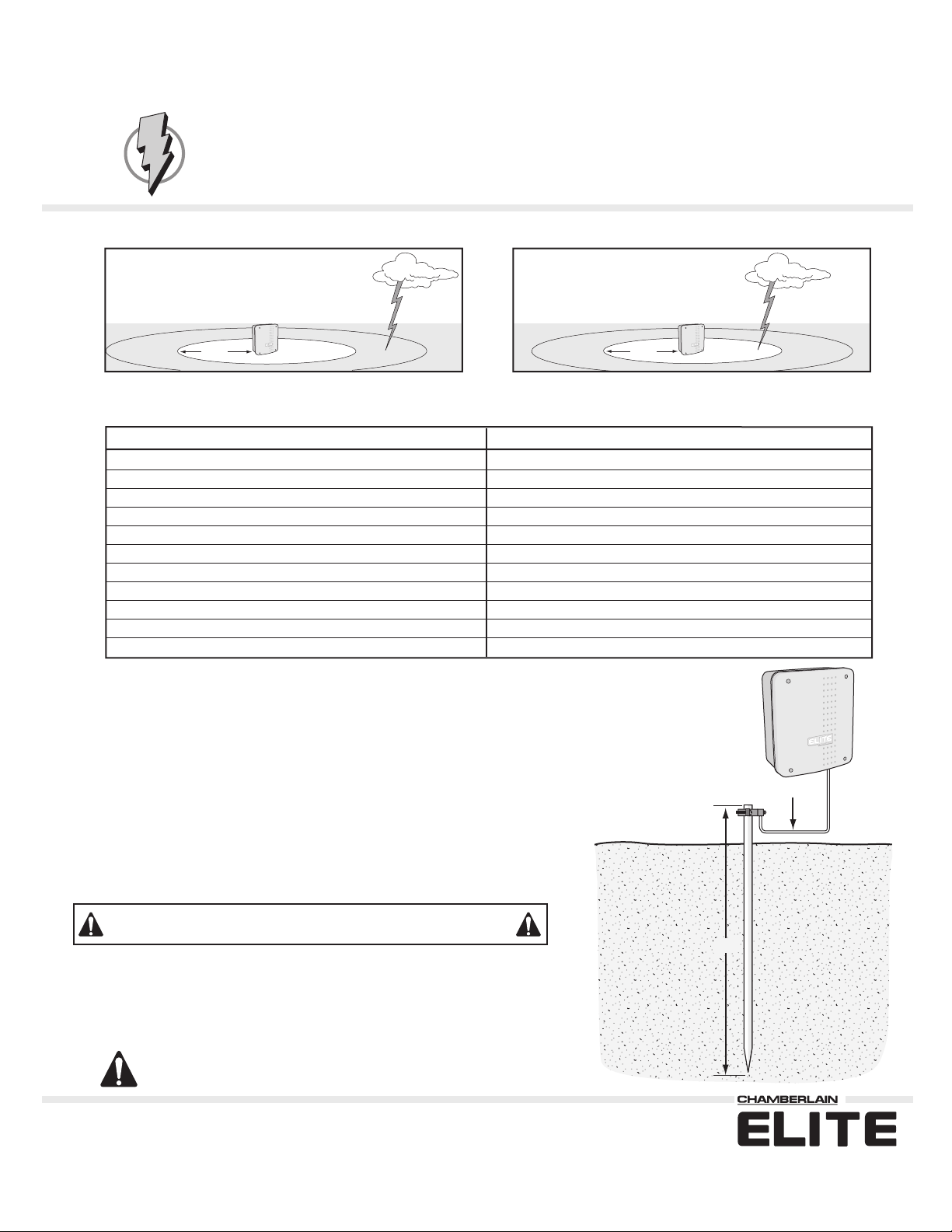
Safe
Possible Damage
50 ft
Properly grounded Miracle-One™
Inputs protected by the Surge Protection Module.
Name of Lines Protected
Motor (Master Unit)
Brake (Master Unit)
Limits (Master Unit)
Motor (Second Unit)
Brake (Second Unit)
Limits (Second Unit)
Center Loop Command
Safety Loop Command
Exit Loop Command
Radio Receiver (Power and Relay)
Power Input
Earth Ground Rod Installation
Proper grounding gives an electrical charge, such as from an electrical static
discharge or a lightning strike, a path from which to dissipate its energy safely into
the earth.
Without this path, the intense energy generated by lightning could be directed
towards the gate operator. Although nothing can absorb the tremendous power of a
direct lightning strike, proper grounding can protect the gate operator in most cases.
50 ft
Properly grounded Miracle-One™
Number of Lines Protected
1
1
1
1
1
1
1
1
1
3
2
12 gauge wire
The earth ground rod must be located within 3 feet from the gate operator. Use the
proper type earth ground rod for your area.
Before digging more than 18" deep, contact local underground utility locating companies
Avoid damaging gas, power, or other underground utility lines.
The ground wire must be a single, whole piece of wire. Never splice two wires for the
ground wire. If you should cut the ground wire too short, break it, or destroy its
integrity, replace it with a single wire length.
Not responsible for improper installation or failure to comply with all
necessary local building codes.
© 2004 The Chamberlain Group, Inc.
All Rights Reserved
8 Ft
®
™
845 Larch Avenue Elmhurst, Illinois 60126
www.chamberlain.com
Page 2

Additional Protection Against Surges
For additional protection against surges, ensure that the cables or wires going to your accessories comply
with the following rules:
for Gate Operators
All wires going the the accessories
The shield
A) At the gate operator: To the chassis of the gate operator
B) At the accessories: To their chassis (Earth grounding at the accessories will be even more beneficial)
Ensure that the connections to the chassis are made as tight as possible to create good contact.
must
be connected as follows:
must
be shielded wires.
01-50741
For Technical Support: 1-800-528-2806
®
© 2004 The Chamberlain Group, Inc.
All Rights Reserved
™
845 Larch Avenue Elmhurst, Illinois 60126
www.chamberlain.com
Page 3

®
Miracle-One™ Surge Protection Board
STEP 1
Unplug transformer.
STEP 5
STEP 2
1
1 Disconnect the battery cable plug first 2 Unplug J3 plug second
3 Unplug J1 plug last.
STEP 6
Step-by-Step Installation instructions
STEP 3
3
2
Remove the control board with 3 screws.
STEP 7
™
STEP 4
Remove the plastic battery rack with 4 nuts.
STEP 8
Remove the batteries from old rack and reinstall them into the new rack.
STEP 9
Rewire the old J1 and J3 plug wires to the surge suppressor terminals.
Place the new battery rack in the control box and secure with the 4 nuts.
STEP 10
Plug transformer back in.
Install the surge suppressor board in position shown with 3 screws supplied.
STEP 11
Reconnect the battery cable plug.
Reinstall the control board in the same screw-hole positions. Connect the J1
and J3 plugs from the surge suppressor board to the control board.
STEP 12
Earth Ground Rod
The green ground wire
MUST
be properly connected to an earth ground rod!
Page 4

®
Miracle-One™ Surge Protection Board
STEP 1
Unplug transformer.
STEP 5
STEP 2
1
1 Disconnect the battery cable plug first 2 Unplug J3 plug second
3 Unplug J1 plug last.
STEP 6
Step-by-Step Installation instructions
STEP 3
3
2
Remove the control board with 3 screws.
STEP 7
™
STEP 4
Remove the plastic battery rack with 4 nuts.
STEP 8
Remove the batteries from old rack and reinstall them into the new rack.
STEP 9
Rewire the old J1 and J3 plug wires to the surge suppressor terminals.
Place the new battery rack in the control box and secure with the 4 nuts.
STEP 10
Plug transformer back in.
Install the surge suppressor board in position shown with 3 screws supplied.
STEP 11
Reconnect the battery cable plug.
Reinstall the control board in the same screw-hole positions. Connect the J1
and J3 plugs from the surge suppressor board to the control board.
STEP 12
Earth Ground Rod
The green ground wire
MUST
be properly connected to an earth ground rod!
 Loading...