

Page 1
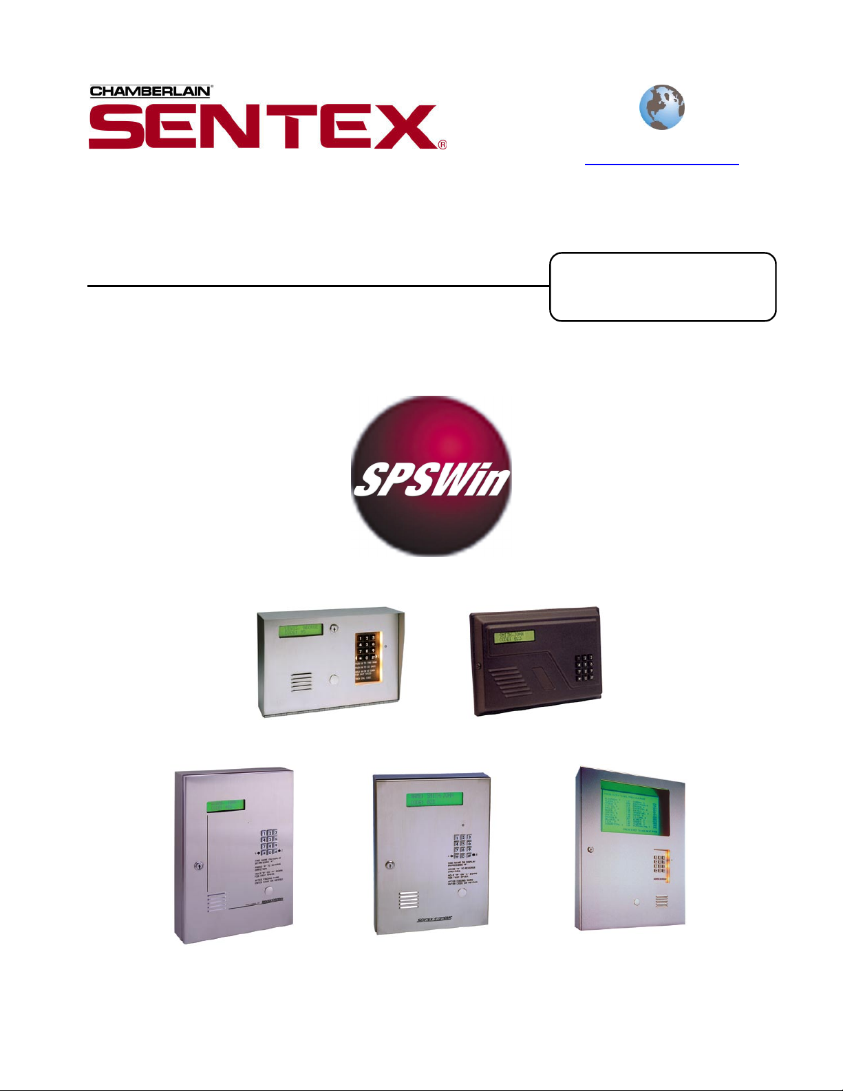
SPSWin
Sentex Programming Software for Windows
User’s Guide
Visit us on the World-Wide Web at
www.sentexsystems.com
Software Version
4.0 and up
Horizon H
Infinity S
Infinity M
Doc 6001647, Rev B
Horizon M
Infinity L
Page 2

Table of Contents
Table of Contents
Installation and Overview..............................3
System Requirements 3
Differences Between SPS and SPSWin 4
Installing SPSWin Version 4.0 (and/or its
companion applications) 5
Windows NT/2000/XP Administrator Notes 7
SPSWin Help and Tables 7
SPSWin Unit Setup Overview 9
Starting SPSWin...........................................10
Starting SPSWin 10
Passwords 10
Creating or Editing an SPSWin Password 11
Main Window Toolbar Reference 11
Communications..........................................12
Accessing Modem Configuration 12
Setting Your Modem Configuration and Connect
Set 12
Connecting to a Unit 15
Communications Options 16
Creating or Editing a Unit Definition
(Stand-Alone Units) .....................................17
Opening a New Unit Definition Window 17
Creating or Editing a Unit Definition (StandAlone) 18
Copying a Unit Definition 18
Creating or Editing a Multi-Link Chain .......19
Opening a New Multi-Link Chain Definition
Window 19
Creating a New Multi-Link Chain Definition 20
Receiving Data from Unit ............................21
Selecting Display Type 21
Downloading Unit Data 22
Verifying Unit Data Has Been Received 24
Upgrading Your Unit(s) 24
Entering and Editing Unit Data ...................25
Time Zones 25
Schedules 27
Holidays 29
Access Levels 30
Access Codes 32
Accessing Unit and Multi-Link Data Fields 38
Creating and Editing Directory Sets (Multi-Link
Only) 39
Relays 40
Settings 41
Messages 44
Firmware 45
Updates 45
Transactions 46
Notes 47
Sending Data to a Unit.................................48
Merging Unit Data ........................................49
Accessing the Merge Feature 49
Setting Merge Priority 50
Viewing Update Results 50
Printing or Exporting Reports.....................51
Accessing Reports 51
Printing Reports 52
Exporting Reports 52
Reports Description 53
Viewing and Printing Transactions.............56
Downloading Transactions 56
Viewing and Printing Transactions 56
On-Line Programming .................................57
Using the On-Line Programmer 57
Using the Control Panel 58
Changing the Unit Password 59
Appendix ......................................................60
SPSWin Main Window Menu Bar 60
Unit Definition Window Menu Bar 63
Control Panel Actions Reference 65
Merge Options (Data Results Reference) 66
Conflict Definitions (Unit Update Status Report) 68
Page 2 of 69
Doc 6001647, Rev B
Page 3
Installation and Overview
Installation and Overview
The procedures in this manual assume that you are familiar with your telephone entry system (Horizon, Infinity,
or Multi-Link).
This chapter will cover . . .
System Requirements
Differences Between SPS and
SPSWin
Installing SPSWin Version 4.0
(and/or its companion
applications)
Each time you finish entering data in SPSWin, you must always either
If you do not perform either Send Changes or Send All after making
Page 3
Send Changes or Send All to the unit, or the changes will not take
effect. For more information, see Sending Data to a Unit on page 48.
changes in SPSWin, your system will not function predictably.
Page 4
Page 5
IMPORTANT INFORMATION
SPSWin Help and Tables
Windows NT/2000/XP
Administrator Notes
SPSWin Unit Setup Overview
Page 7
System Requirements
To run SPSWin, your system must have Windows 95 (full version) or higher and the following:
: For databases having a large number of access codes (e.g., a combination of 1000 or more
Note
directory codes, entry codes, and/or cards), Sentex strongly suggests using the recommended
hardware.
W
INDOWS 95, 98, OR ME® USERS
Minimum Recommended
Pentium 233-megahertz (MHz)
IBM PC-Compatible Computer
64 MB of RAM 128 MB of RAM
240 MB hard disk free 300 MB hard disk free
Internet Explorer 4.01
(Service Pack 2)
Hayes-compatible modem connected to
a COM port
CD ROM
Mouse
800 x 600 Display Setting
Table 1: SPSWin System Requirements (Windows 95, 98, or ME)
Windows 95 Users: You must have Y2K Update installed on your machine.
Windows 98 Users: You must have Y2K Update 2 installed on your machine - does not apply to
Windows 98, Second Edition.
Pentium II 400-megahertz (MHz)
IBM PC-Compatible Computer
Internet Explorer 5.0
Page 7
Page 9
Page 3 of 69
Doc 6001647, Rev B
Page 4
Installation and Overview
WINDOWS NT, 2000, OR XP® USERS
Minimum Recommended
Pentium 333-megahertz (MHz)
IBM PC-Compatible Computer
128 MB of RAM 256 MB of RAM
240 MB hard disk free 300 MB hard disk free
Internet Explorer 4.01
(Service Pack 2)
Hayes-compatible modem connected to
a COM port
CD ROM
Mouse
800 x 600 Display Setting
Table 2: SPSWin System Requirements (Windows NT, 2000, or XP)
Pentium II 400-megahertz (MHz)
IBM PC-Compatible Computer
Internet Explorer 5.0
Windows NT 4 Users: You must have Service Pack 6
(or greater) installed on your machine.
Windows 2000 Users: If you receive an error message stating that you need Windows Installer 2.0,
make sure the CD is your computer’s drive, open Windows Explorer®, go to the CD’s
“\Support\Windows Installer 2.0\Win2000” directory and double-click on the “instmsiw.exe” setup file.
When the setup is complete, double-click the “setup.exe” file on the CD’s root directory to start the
installation again.
Windows NT/2000/XP Users: You must have administrator privileges to install the application.
Differences Between SPS and SPSWin
U
SABILITY
SPS is linear – accessing each feature requires a
step-by-step procedure. SPSWin is a Windows
program – you can access any feature at any time.
V
ERSATILITY
SPS stores basic tenant and unit data. SPSWin also
stores time zones, schedules, holidays, relays, etc.
C
ONVENIENCE
SPS requires the user to look up data one function at a
time. SPSWin displays whole categories of data
together – and allows the user to access any desired
data with a few mouse clicks.
F
AST STARTUP
SPS requires that the unit be installed and connected
before data can be entered. SPSWin allows the user
to enter data without first connecting with the unit, so
as soon as the unit is installed, you are ready to
connect, send data, and go.
D
ATA CONTROL
SPSWin has additional features, including a Merge
Select that gives you power over what data
supercedes when receiving, and a Housekeeping
function that allows you to select how many database
revisions to retain in memory.
Page 4 of 69
Doc 6001647, Rev B
I
CONS AND HIGHLIGHTS
In addition to other Windows features, SPSWin helps
you remember pending unit updates, last unit update,
unit type, what data has been changed, and much
more through the use of highlighting and eye-catching
icons. You no longer have to look for data differences
and easy to forget updates – SPSWin icons and
highlighting make the information jump off the screen
at you.
W
INDOWS FEATURES
SPSWin gives you all he conveniences of Windows,
including Toolbar, Taskbar, function tabs, and dropdown menus that allow instant access to all SPSW in
features.
O
NLINE PROGRAMMER
You may use SPSWin 4.0 to program a unit on-line as
you would with SPS DOS. For more information on
using the on-line programmer, see page 57.
Page 5
Installation and Overview
Installing SPSWin Version 4.0 (and/or its companion applications)
BOUT THE SPSWIN CD
A
This CD includes the installation programs for:
SPSWin (SPS for Windows) – includes Tenant Manager, Data Exchange, and ERMAWin
SPS-DOS (SPS DOS version) – refer to the SPS-DOS User’s Guide for more information.
ERMA-DOS (ERMA DOS version) – refer to the ERMA-DOS User’s Guide for more information.
You may install any of the applications from this CD together or as separate stand-alone applications. The
installation program is located in the root directory and will start up automatically when you insert the CD.
I
NSTALLATION
In order for SPSWin 4.0 or its companion applications to operate properly, it must be installed onto the computer
workstation’s hard disk drive from where the application will be launched. SPSW in 4.0 or its companion
applications cannot be executed directly from the CD. During the installation, you will be prompted to select one
or more applications to install. Enable the checkbox(es) next to the application(s) you wish to install.
Important
:
If you are upgrading SPSWin from an earlier version, you must install version 4.0 in the same
directory where the older version of SPSWin currently resides.
Before installing SPSWin on a computer running Windows® NT, 2000, or XP, review the notes
on page 7.
Users cannot run SPSWin on a central server from remote workstations. All users must have
SPSWin installed on their local computer. However, they can share a database (.mdb file) if
they have read/write capabilities to the server where the database resides. For more information
on sharing databases, see page 7.
To install SPSWin 4.0:
1. Start Windows.
2. Place the SPSWin CD in the CD ROM drive.
SPSWin will automatically start the installation
process; follow the on-screen prompts. If the
installation process does not automatically
start, continue with the instructions below.
3. From the taskbar, click the Start button, point
to Settings on your desktop, then click on
Control Panel.
4. From the Control Panel window, double-click
5. From the Add/Remove Programs screen,
under the Install/Uninstall tab, click Install.
6. Follow the on-screen prompts.
Note
: SPSWin may prompt you to reboot
your machine one or more times during the
installation process. This is required by
Microsoft. If after each reboot SPSWin
does not automatically continue with the
installation, double-click on the setup.exe
file in the SPSWin subdirectory.
on Add/Remove Programs.
If this is a new install, then you’ve completed the installation.
When upgrading from SPSWin ver. 1.04 to 4.0 or above, continue with the Upgrade Conversion
instructions below.
When upgrading from SPSWin ver. 1.05 or above to 4.0 or above, continue with the Upgrade Utility
instructions on page 6.
U
PGRADE CONVERSION FROM 1.04 (16 BIT) TO 4.0 OR ABOVE (32 BIT)
1. Start SPSWin. A dialogue box will inform you that there is a bit-level version mismatch.
2. You will be asked if you want to convert the data to 32-bit. Click the OK button. The information in the
16-bit databases will be copied into 32-bit databases.
3. Do this for both the SPSWin and ERMAWin (Transaction) databases.
Page 5 of 69
Doc 6001647, Rev B
Page 6

Installation and Overview
UPGRADE DATABASE UTILITY FOR ALL VERSIONS
1. Start SPSWin, Tenant Manager, or Data
Exchange. If you get a message stating
“Database Version Mismatch”, you must run the
SPSWin Database Upgrade Utility. Note: If you
do not have access to the SPSWin application,
check with your system administrator.
2. Run the Database Upgrade Utility (under the
Tools menu in SPSWin). OR
From the taskbar, select
>> Sentex Applications >> SPSWin Database
Upgrade Utility.
:
Notes
If at the initial setup your system detects
that MDAC (Microsoft Data Access
Components) version 2.6 must be
installed or reinstalled, click Next. The
system will add it and may require a
restart. Microsoft requires the reboot.
When uninstalling SPSWin 3.0 or
below, Sentex strongly suggests using
the automatic uninstall feature. W e
discourage manually uninstalling
SPSWin 3.0 or below.
Although the system will not overwrite
the database, Sentex still recommends
that you make backup copies.
SPSWin stores information in the
Windows Registry. You can access
this information through the following
location in the registry:
Hkey_Current_User\Software\VB and
VBA Program Settings\SPSWin32.
Important
Receive All command), the download time may vary. The time it takes your system to merge the data
depends on the size of your database, the number of units involved, the capacity of the unit(s), your
computer speed, etc.
To avoid unnecessary download time, determine whether you need to download all the data (Receive
All) or partial data (Receive Settings).
If no data has been entered at the unit itself, there is no need to perform a full download to SPSWin. Or
if you know all the changes that have been made at the unit (and there are only a few), consider
entering the changes into SPSWin yourself rather than performing a full download.
: When downloading data from a unit and merging it to your SPSWin database (with a
>> Programs
3. Run the utility on your SPSWin database(s).
Click on SPSWin. Check the file name and
path. If the file path is incorrect, click
Browse and select the correct file. Click
OK.
4. Run the utility on your ERMAWin databases
(only if your ERMAWin databases were built
before
Check the file name and path. If the file path
is incorrect, click Browse and select the
correct file. Click OK.
All the data from your old databases will be
copied into the new databases.
The SPSWin 4.0 CD provides Internet
Explorer Service Pack 2 for IE 4.01 (installing
with Browser Only will suffice). The
installation includes the following: Browser
Only, Online, Standard, and Full Installation.
To install Service Pack 2, run the
“ie4setup.exe” file. If your version of Internet
Explorer is earlier than 4.01, you will need to
obtain Internet Explorer from Microsoft.
If you want to look at the databases through
a program other than SPSWin, Sentex
recommends that you make a copy of the
databases for that purpose. You can view
the databases using Microsoft Access® 7.0,
or you can export the data for use in other
programs such as Microsoft Excel®.
SPSWin 2.0). Click on ERMAWin.
Remember, you should only need to download all unit data once (before you can send data). When
you download and merge unit data into SPSWin with a Receive All command, the application will
download all the data and merge it into the SPSWin database, regardless of the number of changes that
have been made to the database at the unit(s).
Page 6 of 69
Doc 6001647, Rev B
Page 7

Installation and Overview
SHARING AN SPSWIN DATABASE
A shared SPSWin database enables multiple users to edit its data. An SPSWin database (.mdb file) may be
shared if the database resides on a network server/computer where the SPSWin users have read and write
capabilities. When enabling users to share an SPSWin database, perform and ensure the following:
Locate the SPSWin .mdb file (located in the SPSWin directory). Copy it to the server. Then each user
must select the database. Each user should know that s/he shares the database with another user (or
other users), thereby avoiding any confusion when editing data.
Users sharing the same database should avoid simultaneously editing data for the same units. For
example, while one user edits Unit 1, another should edit Unit 2 or Unit 3. Users may be blocked when
trying to simultaneously edit the same units.
Users sharing the same database should also avoid editing data when another user attempts to transmit
data to/from units associated with the database. This may cause unexpected results.
Windows NT/2000/XP Administrator Notes
If SPSWin will run on Windows NT, 2000, or XP and you are the system administrator, note the following:
B
EFORE THE INSTALLATION
You must have administrator privileges to install SPSWin.
Windows XP Users: If there are multiple SPSWin users, there are two ways to configure your system:
In Windows Explorer®, go to Tools >> Folder Options >> View and disable the “Use simple file
sharing (Recommended)” option. Then provide shared privileges and grant “Full Control” permission
after installing SPSWin (see below). OR
When installing SPSWin, change the install path to the “Shared Documents” directory. The default path
for this directory is “C:\Documents and Settings\All Users\Documents”. Note, however, that installing
SPSWin with this method will provide access to all users.
I
MMEDIATELY AFTER THE INSTALLATION
If there are multiple SPSWin users:
Provide shared privileges for the entire SPSWin subdirectory (and any other directory that will store the
databases) AND
Grant "Full Control" permission for each user to each subdirectory storing the SPSWin databases.
C
HANGING SPSWIN FILES (MULTIPLE USERS)
Since each user has an individual registry, it is advised not to change the location of the SPSWin database.
Database information changed by one user will not be reflected in all users.
N
O "COLLISION/RACE" CONDITION
SPSWin does not currently support record “locking” (i.e., the process whereby only one user may work with the
same database record at a time). Multiple users may simultaneously work with the same database record;
however, doing so may result in data loss or corruption. Please manage multiple users accordingly.
SPSWin Help and Tables
H
ELP
SPSWin has five “help” aids:
Tool Tips are brief descriptions of most buttons and
many screen features.
Status bar help is located near the top of the Main
Screen and at the bottom of the Edit Menu screens.
“What Next?” is a button located in the button menu.
Page 7 of 69
Doc 6001647, Rev B
“Getting Started” is in the Help menu
of the Main Screen.
Online Help is an on-line version of
this manual provided for reference.
Page 8
Installation and Overview
TABLES
Many of the windows include a grid-like format called a table. Each row of the table gives the information for
one unit, access code, access level, etc. Each column header tells what information is listed for each row. See
Figure 1.
Row Selector Column
Column
Column
Header
Row
Indicator
Row
Horizontal
Scroll Bar
Figure 1: Example of Table
Row Selector Column: Select an entire row by
clicking in the Row Selector Column. The row will
be highlighted.
Column Header Row: These entries tell you what
information can be found in each column. You
can change the column width by placing the
mouse pointer over a column divider in the column
header. The icon changes to a double-arrow
sizing icon. Drag the icon to resize the column.
Row Indicator: The triangle indicates the current
row selected. An asterisk () in the row Selector
Column demarcates a new row.
Cells: To edit the information in a cell, click on the
cell. The cell will be highlighted. You can now
change the information in the cell. To move from
cell to cell, you may use the [TAB] key, or click on
the next cell.
Horizontal Scroll Bar: All of the columns may not
fit onto one screen. Use the Horizontal Scroll Bar
to move back and forth to see columns on the left
or right edge of the screen.
Vertical Scroll Bar: All of the rows may not fit
onto one screen. Use the Vertical Scroll Bar to
move up and down to see rows which are off the
top or bottom edge of the window or page.
Page 8 of 69
Doc 6001647, Rev B
To Add Rows: You may add a new row in one of
two ways:
1. Click on the Add or New button. A new
row will appear, ready for you to enter
data.
2. Look for a asterisk () in the Row
Selector Column. Click on a cell in that
row.
To Delete Rows:
1. Click on the row indicator. The row will be
highlighted.
2. Click on the Delete button. The row will
be marked for deletion with an X.
3. When you click on Apply or Done, the
row (and the data) will disappear from the
display.
To Resize Columns: Click and hold a column
divider, move mouse left or right to desired column
position, and release the mouse button. The new
column position will be saved when clicking the
Done button.
Page 9

Installation and Overview
SPSWin Unit Setup Overview
Because SPSWin is capable of so much, new units can require extensive setup if all SPSWin functions are to
be used. When setting up new units (all types except Horizon, which is simpler), Sentex Systems recommends
that you follow the setup sequence provided below.
Notes
:
You do not have to use all the features listed below. Only the steps marked with an asterisk () are
required.
After entering information in each area, do not forget to save the data before leaving the window,
since all data not saved will be lost.
ROFILE PAGE
1. P
6. S
CHEDULES PAGE
Stand-Alone Units: Enter all necessary unit connect
information (baud rate, password, telephone number,
answer type, etc.).
Multi-Link Chains: Create each unit in the existing
ML Chain (using the ADD UNIT icon).
2. M
ESSAGES PAGE
Stand-Alone Units: Select the unit display type.
Multi-Link Chains: Select the display type for each
unit.
3. C
ONNECTION PAGE (RECEIVE DATA FROM UNIT)
Select Receive All or Receive Settings to retrieve all
the necessary unit settings and capacities before you
send data to the unit.
4. H
OLIDAYS PAGE
Create all necessary Holiday dates that will be
referenced by Auto-Unlock and Time Zone schedules.
5. T
IME ZONES PAGE
Stand-Alone Units: Create all necessary time zones.
Make sure to give each zone a name, since this is
how you will select it in the Access Codes page.
Stand-Alone Units: Create all necessary
Auto-Lock / Un-Lock schedules.
Multi-Link Chains: Select all applicable units,
then create all necessary Auto-Lock/Un-Lock
schedules.
7. A
CCESS LEVELS PAGE
Stand-Alone Units: Create all necessary
access levels.
Multi-Link Chains: Create all necessary
access levels (select all applicable units if ML).
8. D
IRECTORY SETS PAGE (MULTI-LINK
ONLY)
Create all necessary Directory sets and select
all applicable units.
CCESS CODES PAGE (ALL UNITS EXCEPT
9. A
HORIZON)
Enter all Tenant names, telephone numbers,
cards, codes, etc. All schedules previously set
up will be accessed from here if needed.
Multi-Link Chains: Create all necessary time zones
for each unit in the Multi-Link chain. Make sure to give
each zone a name, since this is how you will select it
in the Access Codes page.
Page 9 of 69
Doc 6001647, Rev B
Page 10
Starting SPSWin
This chapter will cover . . .
Starting SPSWin
Starting SPSWin
Passwords
Creating or Editing an SPSWin Password
Main Window Toolbar Reference
Page 10
Page 10
Page 11
Page 11
Starting SPSWin
1. Click on .
2. From the fly-up START menu, select
PROGRAMS >> Sentex Applications >>
SPSWin.
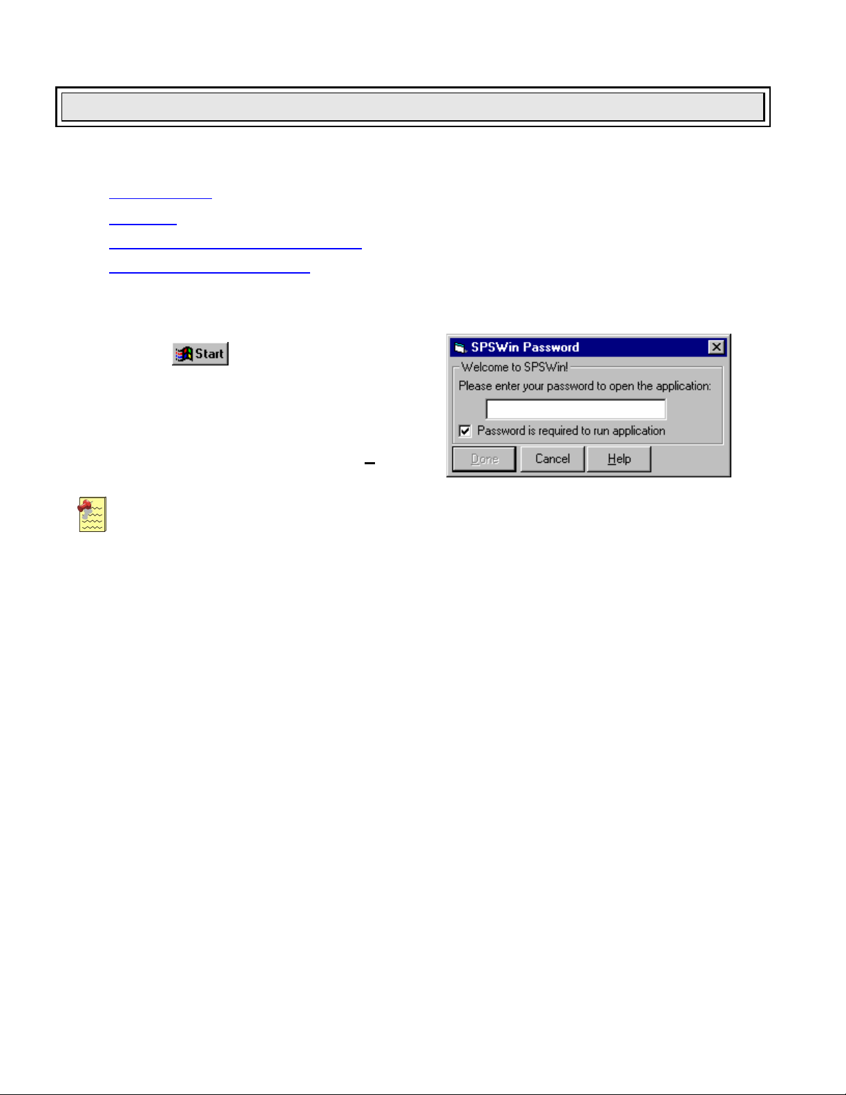
3. If the SPSWin Password screen appears
(Figure 2), enter the password and click D
Notes:
Sentex Applications is the default name of the program group and will appear unless the user has
changed the program group name.
To create a shortcut to SPSW in, drag the SPSW in32 EXE file icon onto the desktop (see Windows
User Guide for details).
one.
Figure 2: SPSWin Password Screen
Passwords
There are two types of passwords used in SPSWin:
U
NIT PASSWORDS
These passwords are required when connecting to a unit and must be 6 numeric digits in length. Unit
passwords also add an extra level of security by allowing you to assign selected units to other SPSWin users.
SPSW
These passwords are not required and can range in length from 1 to 30 characters. SPSWin passwords force
SPSWin users to enter a password when opening the application.
For creating or editing SPSWin passwords, see page 11.
IN PASSWORDS
Page 10 of 69
Doc 6001647, Rev B
Page 11
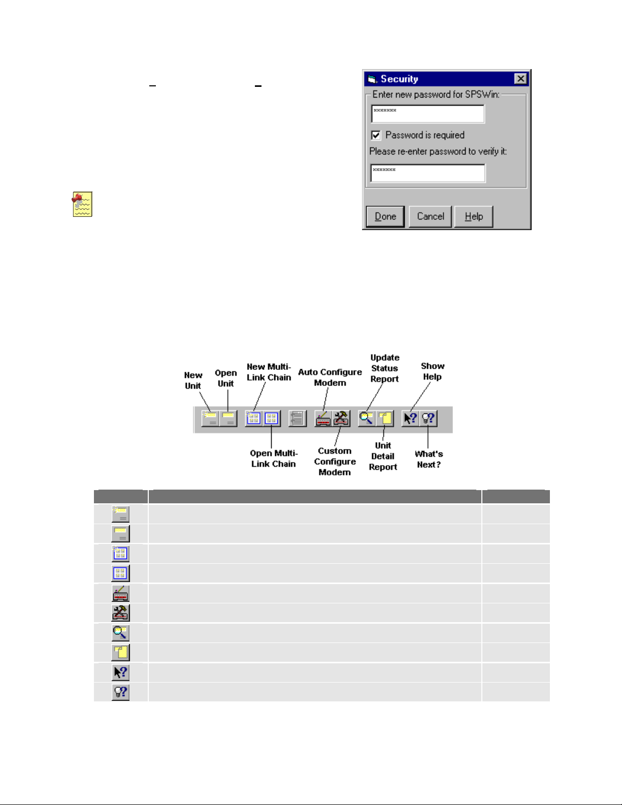
Creating or Editing an SPSWin Password
Starting SPSWin
1. Under the Tools menu bar, select S
2. At the Security window (Figure 3), enter/edit
the password. The password must be entered
twice for verification.
3. To require the password at SPSWin startup,
check the Password is required field.
Removing the checkmark disables the
password requirement.
Notes:
For security, entries are displayed as
asterisks (*) instead of letters.
Up to 30 keyboard characters can be
entered.
Any keyboard character can be used,
including the spacebar.
The password is not case sensitive.
ecurity.
Main Window Toolbar Reference
Figure 3: Security Window
Button Purpose See Page
Creates a new stand-alone unit definition. 17
Opens an existing stand-alone unit definition. 17
Creates a new multi-link chain definition. 19
Opens an existing multi-link chain definition. 19
Prompts SPSWin to automatically configure your modem settings. 12
Allows you to custom configure your modem settings. 14
Runs the Unit Update Status Report. 55
Runs the Unit Detail Report. 53
Opens the SPSWin Help file. n/a
Opens the SPSWin What's Next? hints window. n/a
Page 11 of 69
Doc 6001647, Rev B
Page 12
Communications
This chapter will cover . . .
Communications
Accessing Modem Configuration
Setting Your Modem Configuration and Connect Set
Connecting to a Unit
Communications Options
Page 15
Page 16
Page 12
Page 12
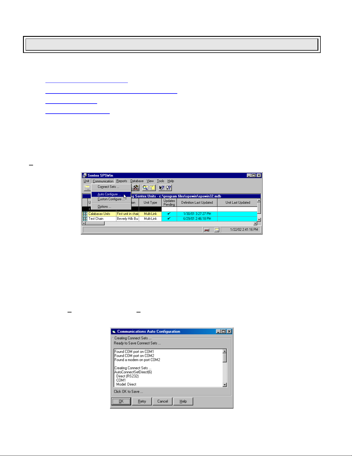
Accessing Modem Configuration
When SPSWin has been successfully started, the Main Window is displayed (see Figure 4). Most SPSWin
functions may be accessed from the Main Window. SPSWin’s modem configuration options appear under the
ommunication menu on the Main Window.
C
Figure 4: SPSWin Main Window with Communications Menu
Setting Your Modem Configuration and Connect Set
When using SPSW in for the first time, allow the application to configure your modem and create one or more
connect sets to be referenced later in a unit definition. A connect set is a set of instructions that tells SPSWin
how to connect with your unit.
A
UTO CONFIGURE
Perform the following instructions to have SPSWin automatically configure your connection settings. At the main
window, select A
Communications Auto Configuration screen (see Figure 5).
uto Configure under the Communication menu option. You will arrive at the
Figure 5: Connect Sets and Modem Configuration Window
Page 12 of 69
Doc 6001647, Rev B
Page 13
Communications
SPSWin will automatically . . .
Search for each COM port on your computer, identifying any modems.
Create a connect set for direct connection (RS232) on each COM port.
Create (2) two connect sets for each modem (300 & 2400 baud).
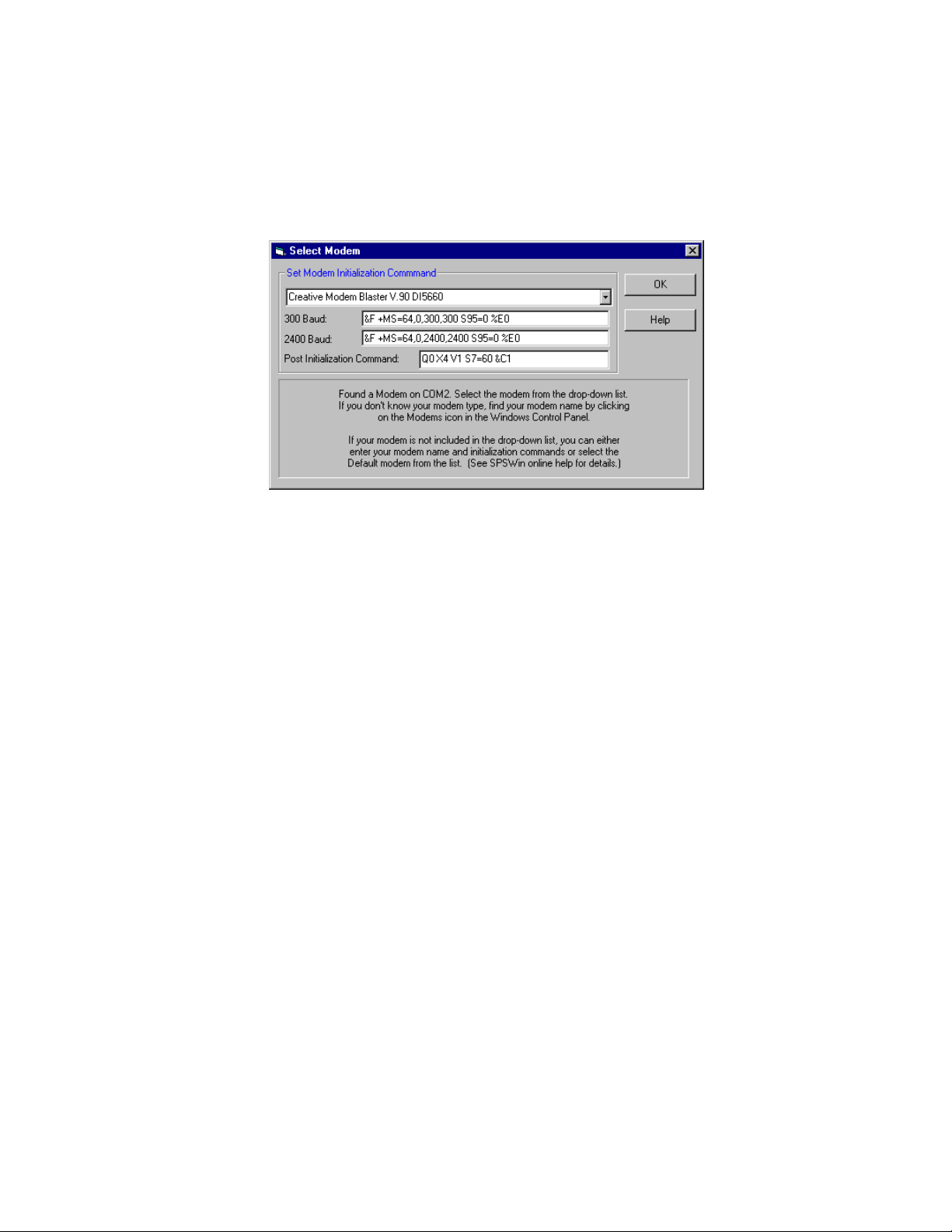
When SPSWin finishes its search, you will arrive at the Select Modem screen for each modem it found (Figure
6).
Figure 6: Select Modem Screen
1. Select the modem from the drop-down field.
Don’t know your modem type? Check your modem settings in your computer’s control panel: Click the
windows Start button (bottom-left corner), go to Settings, Control Panel, and double-click Modems.
If your modem type is not a selection in the drop-down field, you may manually enter the model
type and initialization strings.
If all else fails, select a Default value from the drop-down field and try to connect to a unit. If the
first default setting doesn’t work, try other default settings. Once you have identified which
initialization strings work, you can enter the model name. SPSW in will store these new modem
settings.
2. Click OK.
3. When the window displays “Click OK to save,” it has created and named at least one connect set for
you and is finished. When you are finished saving the connect set, click the Done button to return to
the SPSWin Main Window.
If Auto Configure can’t decipher your modem setup, . . .
Make sure your modem is turned ON and enabled.
Use Retry once or twice. If Retry fails, select Cancel, return to the Main Window, and select
Custom Configure from the Communication drop-down menu.
Page 13 of 69
Doc 6001647, Rev B
Page 14
Communications
CUSTOM CONFIGURE
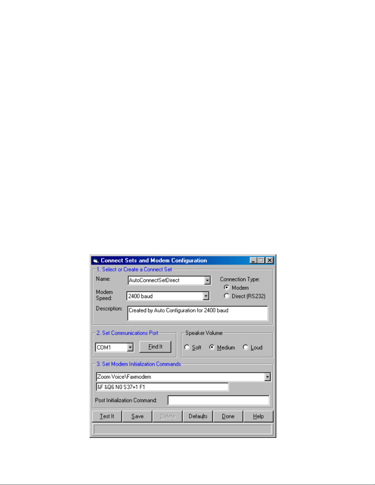
To custom configure your modem and create connect set, perform the following steps:
1. Key in the desired name for the Connect Set
in the NAME field as in Figure 7.
2. Select the desired Connection Type: select
Modem if you are using the telephone, or
Direct if you are using a direct RS232
connection.
3. Select the Modem Speed: 300, 1200, 2400,
and 4800 Baud are available. (Horizon is 300
or 2400 baud only; 4800 baud for Direct
Connect only).
4. If desired, enter any connect set notes in the
Description field.
5. Set Communications Port: unless you know
which communications port to use from
previous experience, select the Find It button
and SPSWin will try to find and enter the
correct communications port for you.
6. Select the desired Speaker Volume: soft,
medium, and loud.
7. Set Modem Initialization Command: Manually
select the modem from the drop-down field.
Don’t know your modem type? Check your
modem settings in your computer’s control
panel (refer to your Windows documentation
for more information).
If the modem type is not a selection in the
drop-down field, you may enter the name
and initialization strings manually.
If this fails, select a Default value from the
drop-down field and try to connect to a
unit. If the first default setting doesn’t
work, try other default settings. Once you
have identified which initialization strings
work, you can enter the model name.
SPSWin will store these new modem
settings.
8. Set Modem Post Initialization Command:
this command is used to tweak problem
modems; changing the default is not
recommended unless you are still
experiencing trouble connecting to a unit. Call
your local Sentex Systems dealer for technical
support assistance.
9. Once the data for this window has been
entered, you must select either the Save or
Done button to save the data. If this data is
not saved, leaving this window will lose all
data entered. Select the Done button to
return to the SPSWin Main Window.
Figure 7: Custom Configure and Create Connect Set Window
Page 14 of 69
Doc 6001647, Rev B
Page 15
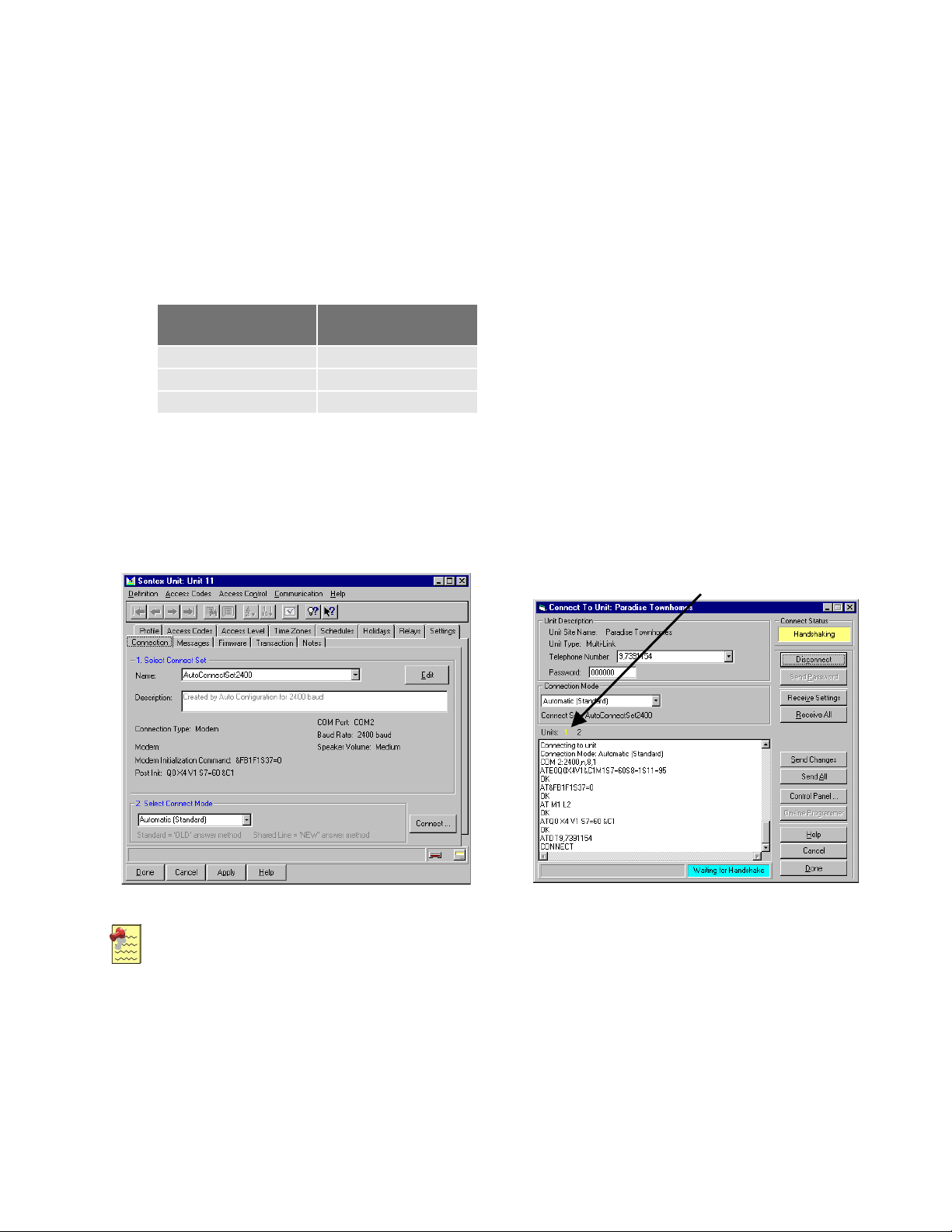
Connecting to a Unit
Communications
1. To start, from the Unit Definition Window, select
the Connection tab to display the Connection
page (see Figure 8).
2. Select the connect set (which you created
earlier) by clicking on the down arrow next to the
Name box, then selecting the connect set name
entered earlier.
3. Select the Connect Mode. There are two
answer modes, each with three subtypes:
Standard
(Old Style)
Shared Line
Automatic Automatic
Timed Automatic Timed Automatic
Manual Manual
If you are using an RS-232 direct connection,
select “Use Direct Connection”.
4. Click on the Connect button. The Connect To
Unit window will be displayed (Figure 9).
5. To start the connection process, select the
Connect button.
When sending or receiving unit data, you
do not need to click the Connect button.
Clicking a Send or Receive button
prompts SPSWin to automatically connect
to the unit.
When the connect process begins, the
Connect Status box (top right of window)
and the status area (lower right of
window) become active. The “Handshake
OK” message will display in the Progress
Window. The Connect button changes to
Disconnect, allowing you to terminate the
connection at any time.
When the Connect Status box turns green
and displays On Line and the status area
at the bottom of the window turns blue
and displays Connected, you are ready to
use the control panel.
6. On the Connect To Unit Window, click on the
Control Panel button. The Control Panel
window will then be displayed.
Select Units
Figure 8: Unit Definition Window Connection Page
Notes:
Shared Line and subtype answer modes are not supported by Multi-Link.
Shared Line is for use with the multiple entry option, in which you have more than one stand alone
unit sharing one telephone line.
Sentex Systems recommends starting out by using Automatic.
If you have problems connecting using Automatic, then try Manual, which allows you to set the time
at which the password is sent.
Once you determine the best time to send the password, select Timed Automatic so you don't have
to reset the Manual answer mode each time you connect with the unit.
Page 15 of 69
Doc 6001647, Rev B
Figure 9: Connect to Unit Window (Multi-Link)
Page 16
Communications
MULTI-LINK CHAINS
Connecting with Multi-Link chains is the
same as for stand-alone units, except that
the Multi-Link connection page has a row of
unit numbers. The user must select the
unit, combination of units, or all units that he
wishes to address.
Double clicking on UNITS selects or deselects all units.
Selecting or deselecting a unit causes it to turn yellow.
When a unit is being contacted, its background turns
turquoise.
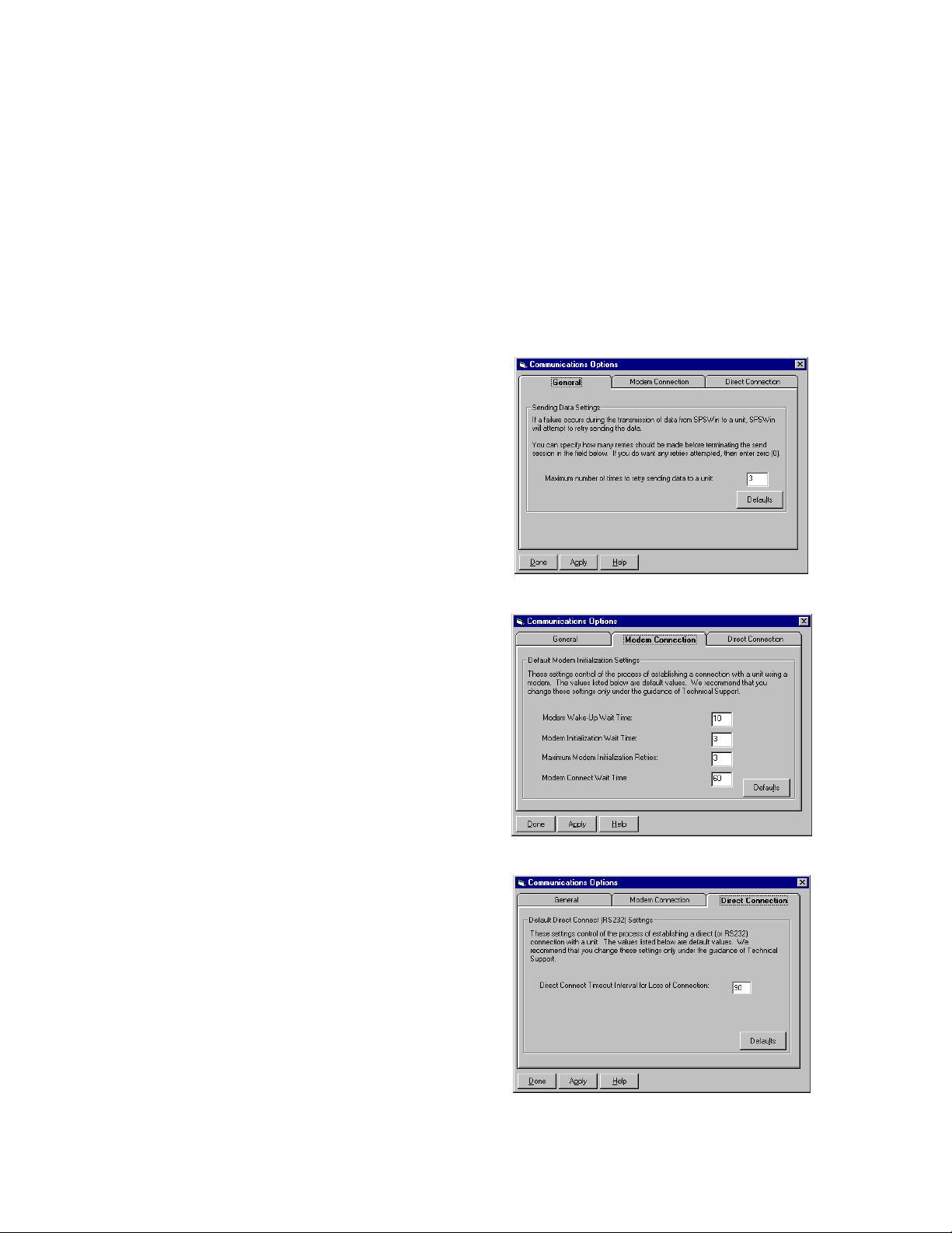
Communications Options
The Communications Options screen (Communication menu >>> Options) allows you to configure particular
communications settings when SPSWin cannot successfully connect to the unit(s) under its current or default
settings. Change the Modem Connection and Direct Connection settings ONLY under the qualified guidance of
your local Sentex Systems dealer.
G
ENERAL
When a communication failure occurs while SPSWin is
sending data to a unit, the software will automatically
attempt to resend the data up to the maximum number
of attempts necessary. To disable the resend
attempts, enter a “0”.
M
ODEM CONNECTION
This tab provides modem control settings.
Modem Wake-Up Wait Time: Controls the
maximum time in seconds for the modem to
respond to a “wake up” call.
Modem Initialization Wait Time: Controls the
maximum wait time in seconds for the modem
to respond to an initialization command.
Maximum Modem Initialization Retries:
Controls the maximum number of retries
attempted during modem “wake up” and
initialization.
Modem Connect Wait Time: Controls the
maximum time in seconds that SPSW in will
wait for a carrier tone before it stops the
connection process.
IRECT CONNECTION
D
During the direct connection process, SPSWin will
time out (i.e., cease the connection process) if it does
not receive input from the unit for the defined number
of seconds.
Figure 10: General Tab
Figure 11: Modem Connection Tab
Figure 12: Direct Connection Tab
Page 16 of 69
Doc 6001647, Rev B
Page 17
Creating or Editing a Unit Definition (Stand-Alone Units)
Creating or Editing a Unit Definition (Stand-Alone Units)
This chapter will cover . . .
Opening a New Unit Definition Window
Creating or Editing a Unit Definition (Stand-Alone)
Copying a Unit Definition
Page 18
Page 17
Page 18
Opening a New Unit Definition Window
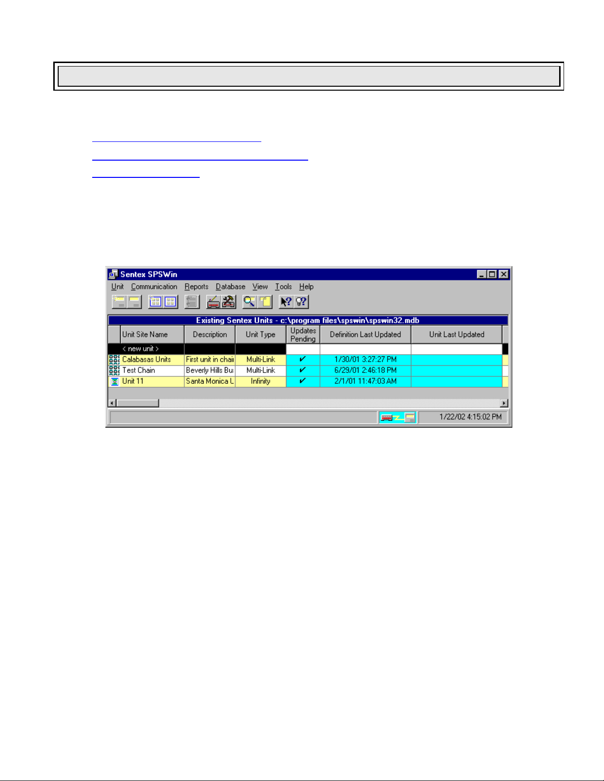
Open the Unit Definition Window by double clicking <new unit> on the Existing Sentex Units field of the SPSWin
Main Window (see Figure 13). A drop down menu will appear, giving you the choice of Unit or Multi-Link. Click
on Unit. The Unit Definition Window and Profile Page will be displayed (see Figure 14).
Figure 13: SPSWin Main Window with <new unit> Displayed
C
OLUMN DESCRIPTIONS
Icon: The far left column displays the graphical
representation of the unit type.
Unit Site Name: Name of stand-alone units or MultiLink chains.
Description: Description of the unit.
Unit Type: Type of unit – Horizon, Infinity, or Multi-
Link.
Updates Pending: A check (“”) appears in this
column if changes have been made, but not yet sent
to the unit; if the column is blank, any changes made
have already been sent.
Definition Last Updated: Date and time anything was
changed in the unit definition, whether or not new
information was sent to the unit. For example, the
description may be changed, but that information will
not be sent to the unit.
Unit Last Updated: Date and time when any changes
were last sent to the unit from SPSW in.
Data Last Received from the Unit: Date and time
when information was last received from the unit.
Unit Short Name: Unique name which identifies
specific unit in the database.
Page 17 of 69
Doc 6001647, Rev B
Page 18
Creating or Editing a Unit Definition (Stand-Alone Units)
Creating or Editing a Unit Definition (Stand-Alone)
The Unit Definition Window contains all the functions necessary to manage a unit, which are indexed like a card
file with “tabs” (see Figure 14). When you access the Unit Definition Window, the Profile Page appears first.
1. Enter the Unit Site Name. This is the name
that will be displayed in the Existing Sentex
Units field of the SPSWin Main Window.
2. Enter the Short Name. Clicking the cursor in
this field causes SPSWin to create the short
name for you. You can change this short
name now, but once it is saved, it must remain
the same, since this is the name the database
will use to correlate all unit data used in
SPSWin. The short name can be a maximum
of six characters.
3. Enter the Unit Type, either Horizon or Infinity,
from the combo box. Click on the data field
and the combo box will drop down. Click on
the desired unit type and the menu will roll
back up and display your choice.
4. If desired, enter any unit notes in the
Description field.
5. Enter the Telephone Number used to
communicate with the unit. If you are directly
connected to the unit via RS-232, leave this
data field blank.
6. Enter the Password required to access the
unit. The factory default is 000000 (six
zeroes). You can change it if desired, or leave
the factory default.
7. Once the data for this window has been
entered, you must select either the Apply or
Done button to save the data.
Figure 14: Unit Definition Window Profile Page
Copying a Unit Definition
When copying a unit definition, SPSWin will create a new unit definition
and copy over all associated data.
1. At the SPSWin main window, select the unit definition that you
want to copy.
2. Under the U
3. At the Copying Unit Definition screen (see Figure 15), edit the
Unit Site Name, if necessary.
4. Edit the Short Name, if necessary. The Short Name is a unique
identification tag the application uses to identify the unit.
5. Click O
nit menu option, select Copy.
K.
Page 18 of 69
Doc 6001647, Rev B
Figure 15: Copying Unit
Definition Screen
Page 19
Creating or Editing a Multi-Link Chain
This chapter will cover . . .
Creating or Editing a Multi-Link Chain
Opening a New Multi-Link Chain Definition Window
Creating a New Multi-Link Chain Definition
Page 20
Page 19
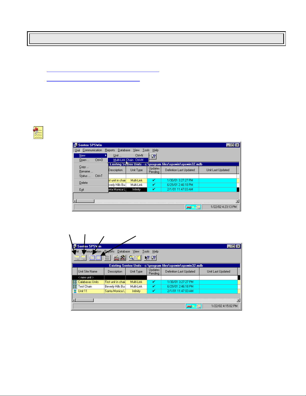
Opening a New Multi-Link Chain Definition Window
Open a new Multi-Link Chain Definition Window by clicking on Unit, New, then Multi-Link Chain on the SPSWin
Main Window Menu, or by selecting the New Multi-Link Chain icon on the main window toolbar (Figure 16). The
Multi-Link Chain Definition Window and Profile Page will be displayed (see Figure 17).
Note: A Multi-Link Chain can consist of up to a maximum of 16 units.
New
Unit
Open
Unit
New
Multi-Link
Chain
Open
Multi-Link
Chain
Figure 16: Opening a New Multi-Link Chain Definition Window
TOP: From Main Window Menu
BOTTOM: From Toolbar Icon
Page 19 of 69
Doc 6001647, Rev B
Page 20
Creating or Editing a Multi-Link Chain
Creating a New Multi-Link Chain Definition
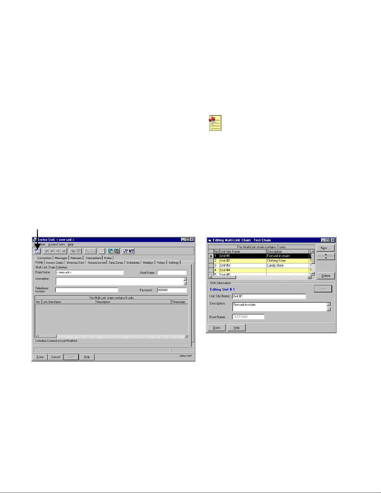
1. Enter the Chain Name. This is the name that will
be displayed in the Existing Sentex Units field of
the SPSWin Main Window.
2. Enter the Short Name. Clicking the cursor in this
field causes SPSWin to create the short name for
you. You can change this short name now, but
once it is saved it must remain the same, since this
is the name the database will use to correlate all
unit data used in SPSWin. The short name can be
a maximum of six characters.
3. Enter notes in the Description field (optional).
4. Enter the Telephone Number used to
communicate with the unit.
5. Enter the Password required to access the chain;
the password should match the one at Unit #1.
The factory default is 000000 (six zeroes). You
can change it if desired.
6. Enter the Unit Site Name and Description in the
Multi-Link chain box. SPSWin automatically sets
the Unit Number (Unit #1) and Timestamps the
entries.
Add Unit
7. To add more units to the chain, select the
“Add Unit” icon on the toolbar or doubleclick on “Unit Site Name” to bring up the
“Editing Multi-Link Chain” window (see
Figure 18, Bottom).
8. Click “New” to add a unit to the chain.
You can optionally change the unit Name
& Descriptions, then click Apply.
Note: You may add more units to your
chain in the Editing Multi-Link chain
window. Perform step 8 only for EACH
unit in your entire Multi-Link chain.
9. When data has been entered, select
either the Apply or Done button to save
the data.
Figure 17: Multi-Link Definition Window Profile Page
Page 20 of 69
Doc 6001647, Rev B
Figure 18: Multi-Link Chain Unit Edit Screen
Page 21
This chapter will cover . . .
Receiving Data from Unit
Receiving Data from Unit
Selecting Display Type
Downloading Unit Data
Verifying Unit Data Has Been Received
Upgrading Your Unit(s)
Page 21
Page 22
Page 24
Page 24
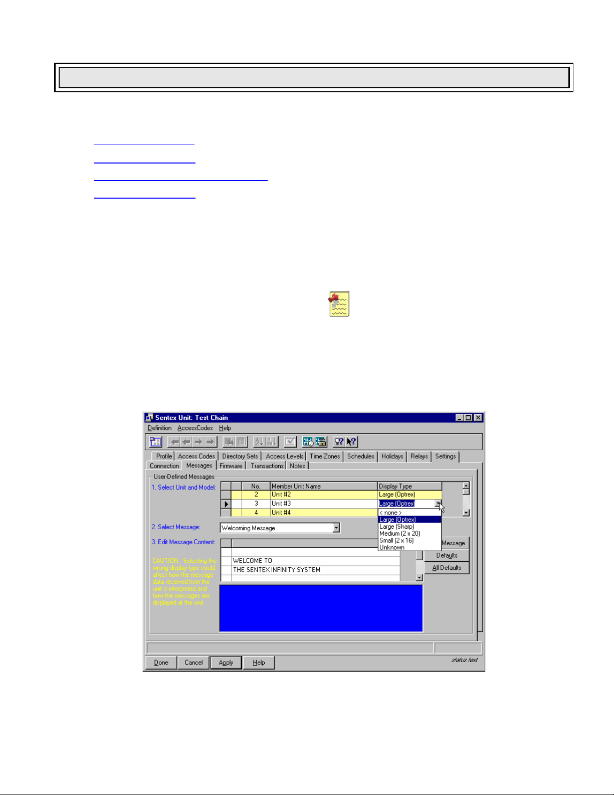
Selecting Display Type
Before connecting with the unit, first select the Display Type.
1. From the Unit Definition Window select the
Messages tab.
The User-Defined Messages page will appear
(see Figure 19).
2. Click on the right arrow to select the Unit and
Model.
3. Select the Display Type by clicking on the
“Unknown” box, just below the “Display Type”
box (to make the drop-down arrow appear);
then click on the down arrow.
4. Select the display type. If unit does not have a
display, then use the “None” selection.
Note: You will not be able to connect to a unit
if any “Display Type” is set to “Unknown”. You
must select a display type for each unit in the
chain to connect to the unit.
5. When display type has been selected, click
either the Apply or Done button to save the
data.
Figure 19: User Defined Messages Page
Page 21 of 69
Doc 6001647, Rev B
Page 22

Receiving Data from Unit
Downloading Unit Data
1. From the Unit Definition Window, select the
Connection tab, and the Unit Definition
Window Connection Page will appear (see
Figure 20).
Note: If you have input unit data that will differ
from the unit data to be downloaded, refer to
Merging Unit Data on page 49.
2. Select the connect set from the Name dropdown field. If no connect set has been
created, you must do so before continuing
(refer to Setting Your Modem Configuration
and Connect Set on page 12).
3. If desired, enter or edit any connection notes
in the Description field.
4. Select the Answer Mode. There are two
answer modes, each with three subtypes.
Standard
(Old Style)
Automatic Automatic
Timed Automatic Timed Automatic
Manual Manual
5. Click the Connect button. The Connect To
Unit window will be displayed (see Figure 21).
6. To start receiving unit data, click on Receive
All or Receive Settings.
Shared Line
Receive Settings: This command downloads
all unit data except
Codes. Use this command if Directory, Entry,
or Card Codes have not
the unit AND unit configuration data (besides
codes) needs to be downloaded to SPSWin
(e.g., the unit has been recently installed or
the unit’s capacities have been upgraded).
Receive All: This command downloads all
unit data, including
Codes (as appropriate for the unit
configuration). Use this command if Directory,
Entry, or Card Codes have
at the unit.
8. Once selected, the unit data is downloaded
directly into the SPSWin database and no
further action is required of the operator.
9. When the connect process begins, the
Connect Status box (top right of window) and
the status area (lower right of window)
become active, and the Connect button
changes to Disconnect, allowing you to
terminate the connection at any time.
10. When downloading is done, click on the Done
button to return to the Unit Definition Window.
Directory, Entry, and Card
been programmed at
Directory, Entry, and Card
been programmed
7. SPSWin gives you a choice of how much data
you wish to receive from the unit:
Figure 20: Unit Definition Window Connection Page
Page 22 of 69
Doc 6001647, Rev B
Page 23

Receiving Data from Unit
Figure 21: Connect to Unit Window
Notes:
Shared Line and subtype connect sets are not
currently supported by Multi-Link.
Shared Line is for use with the multiple entry
option, in which you have more than one stand
alone unit sharing one telephone line.
When using a Shared Line, the unit password
must be numeric (all numbers).
Sentex recommends starting out by using
Automatic. If you have problems connecting
using Automatic, then try Manual, which allows
you to set the time at which the password is
sent. Once you determine the best time to
send the password, select Timed Automatic so
you don't have to reset the Manual answer
mode each time you connect with the unit.
If you want to Send or Receive data, click on
the appropriate Send or Receive buttons; there
is no need to click on Connect first. Use the
Connect button ONLY when using the Control
Panel functions.
When the Connect Status box turns green and
displays On Line, and the status area at the
bottom of the window turns blue and displays
Connected, SPSWin is connected to your entry
system and ready to download unit data.
The unit automatically disconnects from
SPSWin when downloading is completed and
SPSWin automatically processes and merges
the data into the database. Give SPSWin a
few minutes to complete these tasks before
continuing.
MULTI-LINK CHAINS
Receiving data from Multi-Link chains is the same as for stand-alone units, except that the Multi-Link connection
page has a row of unit numbers. You need to select the unit, combination of units, or all units.
Double-clicking on UNITS selects or deselects all units.
Selecting or deselecting a unit causes it to turn yellow.
When a unit is being contacted, its background turns turquoise.
Page 23 of 69
Doc 6001647, Rev B
Page 24

Receiving Data from Unit
Verifying Unit Data Has Been Received
Once the unit data has been received, you can check the Unit Definition window (Figure 22) to ensure the data
has been successfully recorded into the database. You may also want to run the Update Status Report to verify
the download, especially if any warnings
were displayed during the upload/download process.
1. When the Unit Definition window is displayed,
select the tab or tabs labeled for the
information downloaded from the unit:
If you used the Receive Settings
download, select any of the tabs (except
Access Codes) to check for a successful
download.
If you used the Receive All download,
select any of the tabs (as appropriate for
your type of unit) to check for a successful
download.
2. When you are satisfied that downloading was
successful, you may either change any data
desired in preparation for sending an update
(see Entering and Editing Unit Data on page
25), or click on the Done button to return to the
SPSWin Main Window.
Figure 22: Unit Definition Window
Upgrading Your Unit(s)
When you upgrade a Horizon, Infinity, or Multi-Link, you will need to receive the unit’s new settings before you
begin programming it.
1. Open the unit Profile. Refer to Accessing
Unit and Multi-Link Data Fields on page 38.
2. Download the new settings from the unit.
Refer to Downloading Unit Data on page 22.
Page 24 of 69
Doc 6001647, Rev B
3. Check to see that the new settings were
received. Refer to Verifying Unit Data Has
Been Received on page 24.
Page 25

Entering and Editing Unit Data
Entering and Editing Unit Data
Entering and editing data for units and Multi-Link chains is done in the same way. Unit data fields are accessed
in the same way, the same steps for data must be followed, and whether edited or entered for the first time, the
data must be saved or it will be lost when you exit SPSWin. The following sections contain procedures for using
all Unit and Multi-Link Definition window tab functions.
This chapter will cover . . .
Time Zones
Schedules
Holidays
Access Levels
Access Codes
Accessing Unit and Multi-Link
Data Fields
Creating and Editing Directory
Sets (Multi-Link Only)
Note: For information on editing the Profile page, refer to Creating or Editing a Unit Definition (StandAlone Units) on page 17 and Creating or Editing a Multi-Link Chain on page 19.
Page 25
Page 27 Settings Page 41
Page 29 Messages Page 44
Page 30 Firmware Page 45
Page 32 Updates Page 45
Page 38
Page 39
Relays Page 40
Transactions
Notes
Page 47
Page 46
Time Zones
Time Zones are combined with relays to
restrict access in the Access Levels. You
can restrict the access of cards or codes to
specific relays on certain days at particular
times. For example, a janitor's code might
be good only at a rear entrance during the
times of the days he is supposed to be in
your building.
You can create up to 7 restricted time zones,
each of which can contain up to 3 separate
time segments. These zones can then be
assigned to cards or codes as they are
entered into the system. Time Zone 0 has
unlimited access, and cannot be changed.
From the Unit Definition Window, select the
Time Zones tab to display the Time Zones
page (see Figure 23).
Figure 23: Unit Definition Window Time Zone Page
Page 25 of 69
Doc 6001647, Rev B
Page 26

Entering and Editing Unit Data
STAND-ALONE UNITS
1. From the Time Zone page, select a time zone
from 1 to 7 by clicking anywhere in the row,
then clicking on the Edit button. The Creating
Time Zones window will appear (see Figure
24).
2. Time Zone Name: Enter the desired name for
the time zone being created (or edit the name
of the time zone being edited).
3. Description: Enter any notes or description of
the time zone being created (or edit the
description of the time zone being edited).
This field is optional.
4. Segment: Select the time zone segment to be
created/edited by clicking on the desired
segment number (1, 2, or 3) in the Segment
box on the lower left of the window. This will
cause the Set Time Period box to become
active.
5. Set Time Period: Set the Start Time and End
Time for the segment by using the cursor to
select AM or PM and the desired start and end
times.
6. Select Days: Set the days the time segment is
active either by clicking on the desired days
with the cursor, or by using the Select Days
buttons: Weekdays, Weekend, M-W-F, TueThu, or All. To reset the days, select the Clear
button. If holidays are to be included, click on
the Include Holidays box.
7. Save the time zone/segment you have created
or edits by clicking on the Apply button.
8. Return to Step 4 to create another segment, or
to Step 1 to create another time zone.
M
ULTI-LINK CHAINS
Setting time zones for Multi-Link chains is the
same as for stand-alone units, except that the
Multi-Link time zone page has a column for each
unit of the chain that displays the corresponding
time zone number for that unit.
Figure 24: Time Zone Page Edit/Create Screen
Notes:
To set up a time zone that extends past
midnight and into the next day, create one
segment running to midnight (Monday
through Friday, 8 PM to 11:59 PM) and
another segment starting at midnight on
the following days (Tuesday through
Saturday, 12:00 AM to 4 AM).
Holidays may be included or excluded from
a time zone. If excluded, any date
designate as a holiday (such as January
st
1
) will not be included as part of the time
zone if it falls on a day
(such as Monday)
that would otherwise be included.
For a time zone to be valid on a holiday, it must
also be valid for a day of the week. For example, if
you have programmed January 1
and it lands on a Friday, for a code to be valid, the
time zone for that code must be valid on Fridays
as well as for Holidays
programmed to be valid only on holidays and not
Fridays, the code will be considered invalid and
you
will not grant access.
Use the Clear button to erase the time and days
from the displayed time zone.
Use the Clear All button to erase the time, days,
and name from the time zone.
Page 26 of 69
Doc 6001647, Rev B
Figure 25: ML Definition Time Zone Page
st
as a holiday
. If the time zone is
Page 27

Entering and Editing Unit Data
Schedules
Schedules allow you to automatically unlock and relock a door, open and close an electric gate, or control
almost any other function at times you specify through the use of the unit's relays. Each schedule can contain
up to three time segments. For example, doors can automatically unlock at 8AM and relock at 5PM on
weekdays, but unlock only from 8AM to 12 noon on Saturdays.
S
TAND-ALONE UNITS
From the Schedules page, select a relay from 1 to 4 by
clicking anywhere in the row, then click the Edit
button.
Use the Edit button to change an existing
schedule parameter.
Use the Delete button to erase the current
highlighted schedule from the list.
Use the Clear button to erase all the current
schedules from the list.
Figure 26: Unit Definition Window Schedules Page
(Stand-Alone Unit)
M
ULTI-LINK CHAIN
Use the Edit button to change an existing
schedule parameter.
Use the Delete button to erase the current
highlighted schedule from the list.
Figure 27: Schedules Page
Page 27 of 69
Doc 6001647, Rev B
Page 28

Entering and Editing Unit Data
AT THE CREATING AUTO LOCK SCHEDULES WINDOW
1. Schedule Name: Enter the desired name for
the schedule being created (or edit the name
of the schedule being edited).
2. Description: Enter any notes or description of
the schedule being created (or edit the
description of the schedule being edited). This
field is optional.
3. Segment: Select the schedule segment to be
created/edited by clicking on the desired
segment number (1, 2, or 3) in the Segment
box on the lower left of the window. This will
cause the Set Time Period box to become
active.
4. Set Time Period: Set the Start Time and End
Time for the segment by using the cursor to
select AM or PM and the desired start and end
times.
5. Select Days: Set the days the time period is
active either by clicking on the desired days
with the cursor or by using the Select Days
buttons: Weekdays, Weekend, M-W-F, TueThu, or All. To reset the days, select the Clear
button. If holidays will be included, click on
the Include Holidays box.
6. Save the Schedule/segment you have created
or edited by clicking on the Apply button.
7. Return to Step 3 to create another segment or
to Step 1 to create another schedule.
Figure 28: Schedules Page Edit/Create Schedules Screen
Notes:
To set up a schedule that extends past
midnight and into the next day, create one
segment running to midnight (Monday through
Friday, 8:00 PM to 11:59 PM) and another
starting at midnight on the following days
(Tuesday through Saturday, 12:00 AM until
4:00 AM).
Use the New button to add a new schedule to
the list.
Use the Edit button to change an existing
schedule parameter.
Use the Delete button to erase the current
highlighted schedule from the list.
You can exclude holidays from these
schedules, if you wish, so that the door/gates
will not open even though a holiday falls on a
day that would normally be a business day.
For the Auto Lock/Unlock schedule to work
with relays 3 and 4, these relays must be set
as either control or CCTV relays. For
information on setting relays, see Relays on
page 40.
Use the Clear button to erase the time and
days from the current displayed schedule.
Use the Clear All button to erase the time,
days, and name from the current schedule.
Page 28 of 69
Doc 6001647, Rev B
Page 29

Entering and Editing Unit Data
ASSIGNING SCHEDULES TO UNITS/RELAYS (MULTI-LINK SYSTEMS ONLY)
1. At the Sentex Unit Definition window, click the
Relays tab. See Figure 29.
2. Under the Member Unit Name column, locate
the unit/relay row to which you will assign the
schedule.
3. Under the Auto Lock Schedule column, click
the right edge of the cell and select a schedule
from the drop-down list.
4. Click the Ap
5. Click the D
ply button to save your changes.
one button to exit the window.
Holidays
The Holidays page establishes the dates the unit will
treat as holidays in assessing time zones and
automatic lock/unlock schedules. On Holidays, the
normal lock/unlock schedules do not apply.
You can exclude Holidays from Time Zones. For more
information, see Time Zones on page 25.
The Day of Week column is not a data field, but an aid
to tell you which day of the week a particular date falls
on in a particular year.
From the Unit Definition Window, select the Holidays
tab to display the Holidays page (see Figure 30).
S
TAND-ALONE UNITS
1. From the Holidays page, select a holiday by
clicking anywhere on the row, then clicking on
the Edit button. The Setting a Holiday window
will appear, as shown in Figure 31.
Figure 29: Relays Page
Figure 30: Unit Definition Window Holidays Page
2. Holiday Name: Enter the desired name for
the holiday being created (or edit the name of
the holiday being edited).
3. This Holiday Occurs On: Set the date of the
holiday by using the arrows on either side of
the date box. Arrows on the left change the
month and arrows on the right change the day
of the month.
If not already set to the proper year, use the
drop-down menu to select the year. SPSWin
automatically calculates the day on which the
holiday will fall.
4. Save the holidays you have created or edited
by clicking on the Done button.
5. Return to Step 1 to create another holiday.
Page 29 of 69
Doc 6001647, Rev B
Figure 31: Holidays Page Setting a Holiday Screen
ULTI-LINK CHAINS
M
Setting holidays for Multi-Link chains is the same as
for stand-alone units, except that the Multi-Link
holidays apply to every unit of the chain.
Page 30

Entering and Editing Unit Data
Access Levels
Access levels allow you to restrict access of cards or codes to certain times, during certain days at certain
entrances. They can be valuable in providing limited entry access to maintenance, gardening and other nontenant personnel. You can create as many access levels as you wish.
From the Unit Definition Window, select the Access Levels tab to display the Access Levels page (see Figure
32).
S
TAND-ALONE UNITS
1. Access Level Name: Enter the desired
access level name.
2. Door 1: Select or deselect Door 1 for this
access level.
3. Door 2: Select or deselect Door 2 for this
access level.
4. Time Zone: Click on the field to display the
drop-down menu arrowhead. Click on the
arrowhead to display the drop down menu.
Select the desired time zone and the menu will
roll up and display your choice.
Note: To use this feature, Time Zones must
be created (see Time Zones on page 25).
5. Description: Enter any description or notes
pertinent to this access level.
6. Return to step 1 to create additional access
levels.
7. Once the data for this window has been
entered, you must select either the Apply or
Done button to save the data. If this data is
not saved, leaving this window will lose all
data entered.
Figure 32: Unit Definition Window Access Levels Page (for Infinity)
Page 30 of 69
Doc 6001647, Rev B
Page 31

Entering and Editing Unit Data
MULTI-LINK CHAINS
For Multi-Link applications, the Access Levels page contains a column for each unit’s relays and time zone,
which allows you to specify the units and relays.
1. Access Level Name: Enter the desired
access level name.
2. Description: Enter any description or
notes pertinent to this access level.
3. Relay 1: Select or deselect Relay 1 for
this access level for each unit in the chain.
4. Relay 2: Select or deselect Relay 2 for
this access level for each unit in the chain.
5. Time Zone: You must select a time zone for each
unit in the chain. Click on the field to display the
drop-down menu arrowhead. Click on the
arrowhead to display the drop down menu. Select
the desired time zone and the menu will roll up and
display your choice.
Note: To use this feature, Time Zones must be
created (see Time Zones on page 25).
6. Return to step 1 to create additional access levels.
Once the data for this window has been entered, you must select either the Apply or Done button to save the
data. If this data is not saved, leaving this window will lose all data entered.
Figure 33: Unit Definition Window Access Levels Page (for Multi-Link)
Page 31 of 69
Doc 6001647, Rev B
Page 32

Entering and Editing Unit Data
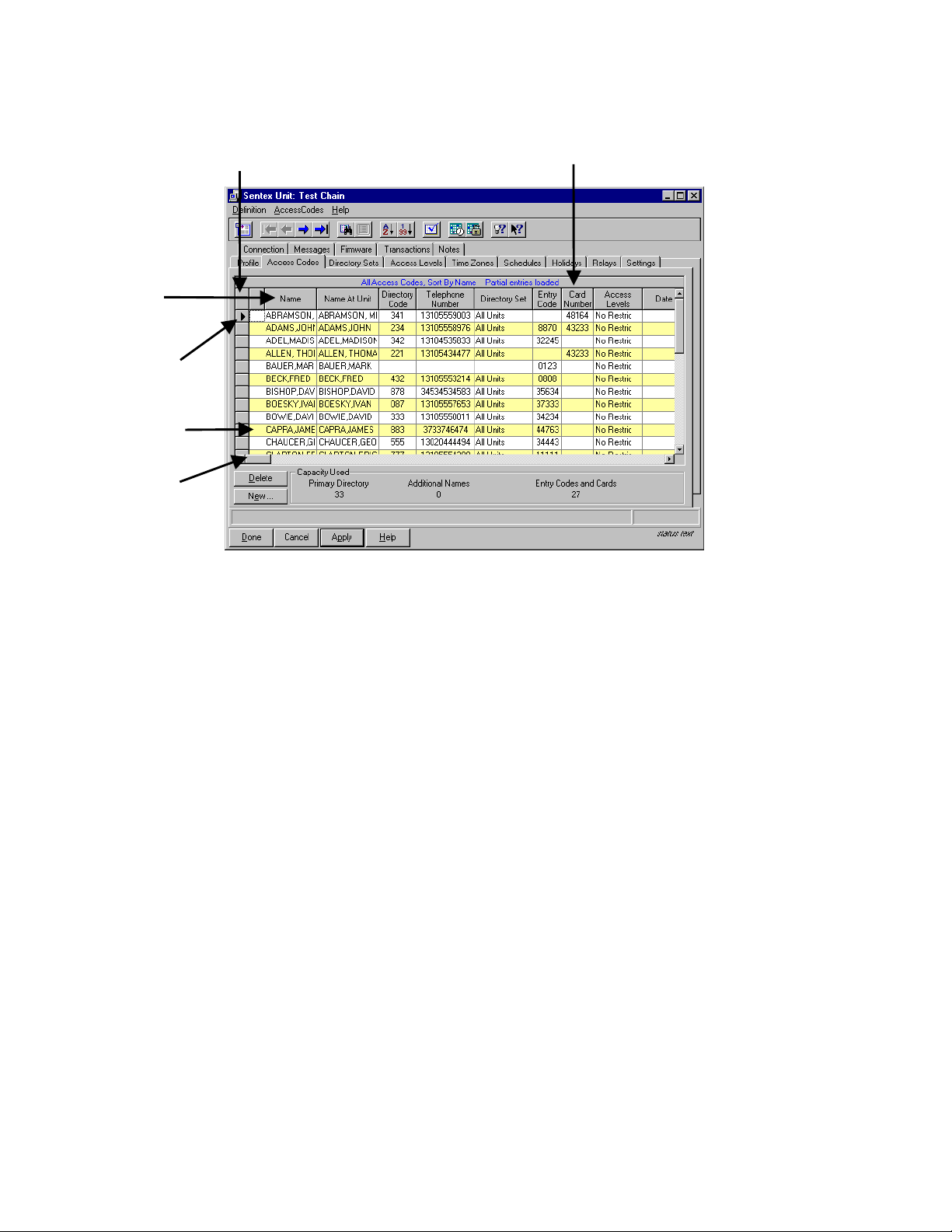
Access Codes
The Access Codes page (see Figure 36) allows you to enter access codes and create your directory from the
same window, since data entered here becomes part of the database.
A
BOUT DISPLAY SETS
Before entering data or searching for entries, understand the way SPSWin displays its access code entries.
SPSWin displays these entries in “Display Sets”. Similar to an Internet search that yields too many records to
display all at once, a display set is a defined amount of entries displayed on the grid at one time. You can
define the amount of entries yourself, definable at the E
bar option (see Figure 34 and Figure 35).
Let’s look at an example. Imagine that you have roughly 1000 Access Code entries and you’ve set the Entries
to Load at 100. You will end up with roughly ten display sets, each containing 100 entries. To view different
display sets, you can jump from set to set with the Get First, Get Previous, Get Next, and Get Last buttons (see
Searching & Sorting Entries on page 35).
TIP: As with any software application, the more entries the application tries to load at one time, the
longer the application will take to load them. Enter the number of Entries to Load accordingly.
ntries to Load option under the Access Codes menu
Figure 34: Entries to Load Location
Figure 35: Entries to Load Window
Figure 36: Unit Definition Window Access Codes Page
Page 32 of 69
Doc 6001647, Rev B
Page 33

ENTERING ACCESS CODES
Entering and Editing Unit Data
1. Name: Enter the tenant's full name, using up
to 50 characters.
2. Directory Name/Name at Unit: The name
that will be sent to the unit. When you click on
this field, SPSWin automatically enters the
tenant's name in uppercase letters; you can
enter an alternate name (i.e., MANAGER) or
delete the entry. The number of characters
allowed is as follows:
For Horizons, Infinity L, Infinity S, and Infinity
M: 13.
For Infinity L and Infinity M (both with
Commercial Firmware): 35.
3. Directory code: Enter the code visitors will
key in to dial the tenant's telephone number, if
the tenant will need a directory code.
4. Telephone number: Enter the tenant's
telephone number (required if you entered a
Directory code for the tenant).
5. Entry code/card: Enter the entry code or
card code the tenant will use to gain access to
the building, if required.
6. Access levels: Enter the access levels by
clicking on the data field. A drop-down menu
will appear, listing all access levels available.
Select the desired level and the menu will roll
up and display your choice.
7. Date Limit (optional) – Infinity and Multi-
Link Only : You have the option of limiting the
time an Access Code can be used. Enter the
last date on which you want the Access Code
used. The Access Code will grant access
from the time you send data to the unit, until
the end of the date you entered. For example,
if you enter “09/30/2003”, the Access Code will
grant entry until midnight, 1 October, 2003.
8. To the right of the Access Levels column are
five user-defined columns or fields (see Figure
40), which can be used to store any type of
(optional) data the user wants to track. This
data will not be sent to the unit. This data
field is for user purposes only.
9. Enter all additional access codes, then select
either the Apply or Done button to save the
data. If the data is not saved, by leaving this
window, you will lose all entered data.
Important: You must click Apply to save any
changes.
Also, if your entry disappears after you select
the Apply button, this behavior is normal. The
application may (depending on your
search/sort and Entries to Load settings) move
the entry out of view (see About Display Sets
on page 32 for more information).
Note: You must first create Access Levels
(see Access Levels on page 30); AND you
must enter an Entry Code to use Access
Levels.
M
ULTI-LINK
Use Limit (optional): You can place a limit on the number of times an Access Code can be used. Enter the
number of times (1-9) you want the Access Code to grant access. After you send the data to the unit, the
number of uses will begin counting down. For example, if you enter “6”, the Access Code will deny access on
the 7th try.
Note: Only the Multi-Link has the capability of specifying either a Date Limit or a Use Limit for any one
Access Code.
Page 33 of 69
Doc 6001647, Rev B
Page 34

Entering and Editing Unit Data
BULK-LOADING CODES
The Enter Range of Codes feature allows you to bulk-load a large number of entry codes/cards into the system
at one time. Names cannot be associated with entry codes/cards when entered as a group, but may be added
to individual records later.
Example: You have just received 250 cards to enter into
the system. Why bulk-load them? Every time someone
needs a card, you won't have to individually generate a
Note: All cards entered in the
same group will have the same
access level.
new card in SPSWin right away. You can give someone
the group card, which has its own code, and then return
later to assign a name to that card.
1. At the Unit Definition window, under the
A
ccess Codes menu option, select New -->
Code G
roup. You will arrive at the Enter
Range of Codes window (see Figure 37 and
Figure 38).
2. From/To: Enter the code range in the From
and To boxes.
3. As: If your system supports both entry codes
and cards, select to enter Entry Codes or
Card Codes.
Figure 37: Enter Range of Codes Window (Units
Supporting Entry Codes and Cards)
4. Access Level: Assign an access level to the
group of cards/codes. Refer to page 30 for
more information on access levels.
5. Click the D
one button.
D
ELETING ACCESS CODES
The Delete Access Codes feature allows you to . . .
Delete a single access code record.
Delete all access codes from the current
display set (see page 32 for more information
on display sets).
Delete all of the directory codes, entry codes,
and/or card codes from the current display set.
1. At the Unit Definition window, under the
A
ccess Codes menu option, select Delete.
You will arrive at the Delete Access Codes
window (Figure 39).
2. Select your delete options.
3. Click O
K.
Figure 38: Enter Range of Codes Window (Units
Supporting Entry Codes Only)
Figure 39: Delete Access Codes Window
Page 34 of 69
Doc 6001647, Rev B
Page 35

Entering and Editing Unit Data
USER DEFINED COLUMNS
You may wish to track additional information about each person listed in the directory. SPSWin gives you five
additional columns (fields) in which to enter such information.
1. Click on the Access Codes menu at the top of
the Unit Definition Window (Figure 36).
2. Click on the User-Defined Fields … .
3. The User-Defined Fields Entry screen
displays.
4. Click in one of the boxes under User-Defined
Field Name. Enter the name of the field you
wish to use. For example, “No. of persons
using unit”. You may enter up to five field
names.
5. When you are finished, click on the Done
button. This will save the fields. If you do not
wish to save the field names, click on the
Cancel button. The Access Codes Page will
be displayed. You may now continue editing
the access code and directory information
Figure 40: User Defined Fields Entry Window
including your new fields.
S
EARCHING & SORTING ENTRIES
When you’re working with a large number of entries, SPSWin provides search and sort features that allow you
to locate a specific group of entries or one particular entry.
Use the reference section below to perform all the related search/sort functions:
Get First
Sort By Code
Get Previous
Get Next
Get Last
Search
Get All
Sort By Name
Toolbar Button Press This Button To . . .
Get First
Get Previous
Get Next
Get Last
Search
Get All
Move to the first display set if you have multiple sets.
Move to the previous display set if you have multiple sets.
Move to the next display set if you have multiple sets.
Move to the last display set if you have multiple sets.
Perform an entry search (see Figure 41).
Re-retrieve all entries. This function is useful after you finish
validating data, bulk-loading entries, or performing an entry search.
Sort By Name
Sort By Code
Sort the display by tenant name (see Figure 42).
Sort the display by directory, entry, or card code (see Figure 43).
Page 35 of 69
Doc 6001647, Rev B
Page 36

Entering and Editing Unit Data
Step 1: Select the type of data
you want to search.
Step 2: Select the comparison
value (e.g., begins with, contains,
etc.).
Step 3: In the Value field, enter
the name, code, etc. you are want
to locate.
Step 4: Click OK.
Step 1: Select the Sort By option.
Step 2: Select the Sorting Order.
Ascending sorts from A to Z.
Descending sorts from Z to A.
Step 3: Click OK.
Figure 41: Record Search Window
Figure 42: Sorting by Name
Step 1: Select the Sort By option.
Step 2: Select the Sorting Order.
Ascending sorts from 1 to > 1
(greater than 1). Descending sorts
from > 1 (greater than 1) to 1.
Step 3: Click OK.
Figure 43: Sorting by Code
Search Tips:
Explore the different ways of searching and sorting access code records by reviewing the Data and
Comparison drop-down boxes on the SPSW in Specify Access Code Record Subset screen (Figure
41).
Sorting Only Directory
Codes: To view a list of directory codes, click the Search button (see page
35), select “Directory Code” from the Data drop-down box, select “is greater than or equal to” from the
Comparison drop-down box, and enter “0” in the Value text box.
Sorting Only Entry
Code” from the Data drop-down box, select “is greater than or equal to” from the Comparison dropdown box, and enter “0” in the Value text box.
Sorting Only Card
Number” from the Data drop-down box, select “is greater than or equal to” from the Comparison dropdown box, and enter “0” in the Value text box.
Codes: To view a list of entry codes, click the Search button, select “Entry
Codes: To view a list of card codes, click the Search button, select “Card
Page 36 of 69
Doc 6001647, Rev B
Page 37

Entering and Editing Unit Data
VALIDATING DATA
When you validate your data, SPSWin checks for conflicting or erroneous data and displays the invalid entries
on the Access Codes page (see Figure 44).
= Validate
Sentex Systems recommends that you
validate your data if:
You have added a significant amount
of entries.
You are experiencing system
difficulties.
To return to the normal view after validating
your data, click Get All.
Note: After correcting any invalid
entries, re-do the validation to ensure
all problems have been corrected.
Figure 44: Validating Data
E
RROR MESSAGES
Incorrect or insufficient data is indicated either by a yellow exclamation mark or a lined red circle, and
explanatory messages appear on the status bar at the bottom of the grid as follows:
Invalid dir code – no phone number:
Directory codes must have telephone numbers
to be valid.
Mismatched directory code & telephone
number: Once directory code and telephone
number have been entered, if entered again
(i.e., for another person in the apartment), they
must match. To group the mismatched entries
together, sort by directory code.
Duplicate entry code / card number for at
least one of the access level member units:
Duplicate entry codes / card numbers exist. To
group the duplicate codes together, sort by
card or entry code.
Note: An entry code and a card code with an
equal numeric value (e.g., entry code 0001
and card code 00001) are considered
duplicate numbers (since the value of the
aforementioned example equals “1”).
Dir code size exceeded: The directory code
has too many digits.
Entry code size exceeded – (Stand-Alone
Units): The entry code has too many digits.
Entry code size exceeded for at least one
of the access level member units – (Multi-
Link): The entry code has too many digits for
one of the units in this particular access level.
Both a date limit & use limit are defined –
(Multi-Link only): Date limits and use limits
cannot both be specified. Choose one.
Invalid Entry/Card – An entry or card code
exceeded 65534. Enter a lesser number.
Page 37 of 69
Doc 6001647, Rev B
Page 38

Entering and Editing Unit Data
Accessing Unit and Multi-Link Data Fields
1. Stand-Alone Units: In the SPSWin Main Window, double click on the desired unit name in the Unit
Site Name column of the list of Existing Sentex Units, OR click on the Open Unit icon (see Figure 45).
Multi-Link Chains: In the SPSWin Main W indow, double click on the desired Multi-Link chain name in
the Unit Site Name column of the list of Existing Sentex Units, OR click on the Open Multi-Link Chain
icon (see Figure 45).
2. The Unit or Multi-Link Chain Definition window will be displayed.
The Unit and Multi-Link Chain Definition Windows contain all the functions necessary to manage a
unit or chain, and are indexed like a card file with "tabs".
The Profile Page appears first. You may then select the tab or tabs for the unit information you wish
to enter or edit.
3. Enter or edit data as desired. When you are finished, remember to save the data by selecting the
Apply button, then click on the Done button to return to the SPSWin Main Window.
>> New Unit
>> Open Unit
>> New Multi-Link Chain
>> Open Multi-Link Chain
Figure 45: SPSWin Main Window Unit Site Name Selection
Page 38 of 69
Doc 6001647, Rev B
Page 39

Entering and Editing Unit Data
Creating and Editing Directory Sets (Multi-Link Only)
Directory sets are a Multi-Link feature that allow you to define which directory codes and telephone numbers will
be sent to and be valid at which units.
The first step in using directory sets is to create the subset of units, or Directory Set, in this window.
The second step is to enter all the desired the codes and telephone numbers in the Access Codes
window, which displays ALL codes for ALL units.
The third step is to select which tenants will be part of which directory sets in the Access Levels
window.
Create directory sets as follows:
1. Select the Directory Sets tab from the MultiLink Definition Window.
2. Click on New, below the directory sets list, to
create a new directory set.
3. Enter the directory set name in the Directory
Set Name column. This is the name you will
select in the Directory Set column of the
Access Codes page.
4. Enter the directory set description (optional).
5. To enter a unit in a directory set, click on that
number unit’s column. A check mark in that
column means that unit has been selected for
that directory set (pressing any key on your
keyboard toggles between selected and not
selected).
6. To alter an existing directory set, click on the
desired name in the Directory Set Name
column, then select or deselect units as
desired.
7. When directory set selection is finished, select
either the Apply or Done button to save the
data. If the data is not saved, leaving this
window will lose all data entered.
Note: In the example shown in Figure 46, any
directory code assigned to the directory set
named Entry Tenants will be displayed at units
4, 5, 6 and 7.
Figure 46: Unit Definition Window Directory Set Page
Page 39 of 69
Doc 6001647, Rev B
Page 40

Entering and Editing Unit Data
Relays
From the Multi-Link Chain Definition Window, select the Relays tab to display the Relays page (see Figure 47).
A
BOUT RELAYS
The Relays page allows you to set or edit relay
settings. When setting your relays, ask yourself:
"How do I want the door (via the relay) to respond to a
card or entry code?"
“Is the door set up to sound an alarm, if forced open?"
"How long an activation time (e.g., door open time) do
I want to assign the relay(s)?"
S
TAND-ALONE UNITS
Definition: A relay is a device that responds to an
electric current by activating other devices.
Relay Control Options: You may set the Infinity
or Horizon system, for example, to lock or unlock a
door/gate (Control), re-route alarm contacts
(Shunt), signal an alarm (Alarm), or turn on a
closed circuited television (CCTV).
1. Relay Name: Enter the relay name and any
other short notes (this data is not sent to unit).
2. Activation Time: Enter the desired activation
time in seconds. Relays can be set to activate
from zero (0) to 99 seconds.
3. Controls: Select the desired relay function:
For Infinity and Multi-Link: Relay 1 and
Relay 2 are set to control and cannot be
changed.
Select the relay function for relay 3 and relay 4
from the drop-down menu. Click on the data
field and an arrowhead will appear. Click on
the arrowhead and the drop-down menu will
appear. Click on the desired function (control,
shunt, alarm or CCTV), and your choice will be
displayed.
For Horizon: Relay 1 is set to control and
cannot be modified.
Select the function for relay 2 from the dropdown menu. Click on the data field and an
arrowhead will appear. Click on the
arrowhead and the drop-down menu will
appear. Click on the desired function (control,
shunt, alarm or CCTV), and your choice will be
displayed.
4. When you are done entering relay settings,
click on the Apply button to save the data.
M
ULTI-LINK CHAINS
Setting relays for Multi-Link chains is the same as
for stand-alone units, except that the Multi-Link
relays page has a separate row for each unit of
the chain.
Figure 47: Multi-Link Chain Definition Window Relays Page
Page 40 of 69
Doc 6001647, Rev B
Page 41

Entering and Editing Unit Data
Settings
From the Unit Definition Window, select the Settings tab to display the settings page (see Figure 48).
The Settings page allows you to set or edit the unit settings.
Settings can be retrieved from the unit by connecting with the unit and selecting either Receive Settings
or Receive All (see Receiving Data from Unit on page 21).
H
ORIZON (STAND-ALONE UNITS)
1. Number of Digits in a Directory Code: Input
the number of digits used in directory codes
(usually 3).
Note: Decreasing the number of digits may
make longer directory codes invalid. You will
need to change the longer directory codes to
fit the shorter directory code length.
2. Number of Digits in an Entry Code: This
number is displayed for reference only.
3. Maximum Number of Keypad Errors: Sets
the number of keypad errors before the unit
stops accepting codes for 3 minutes and
closes a relay or places an alarm call if options
are enabled.
4. Number of Rings Before Answer: Set the
number of rings before answering the
phone/modem.
5. Talk Time (in seconds): Input how long you
want a visitor to be able to talk to a tenant.
6. Zero Dials Directory Codes: Check this box
if you want the unit to automatically dial the
person currently listed on the unit’s display.
7. Jump to Middle of Display: You may wish to
use this option if your directory is very long.
The first time a visitor presses the pound key
(#), the middle of the directory name/name at
unit will be displayed.
8. Auto-Prefix Long Distance Phone Numbers
With 1: Check this box if you must dial 1 to
make long distance telephone calls in your
area.
9. Alarm Phone Number: If the unit has been
programmed to make an alarm call, the
telephone number is displayed. Otherwise,
“Alarm call disabled” is displayed.
Note: Alarm calling must be programmed at
the unit. See Horizon Programming and Use,
document # 6001036.
10. PBX Digit: If calls to unit will go through a
PBX system, enter PBX prefix number.
11. Dialing Type: Select tone dialing unless pulse
is the only type available to you.
12. Answer Method: If multiple stand-alone
units/entrances share one phone line, select
Shared Line. Default is Standard.
Figure 48: Horizon Unit Definition Window Settings Page
Page 41 of 69
Doc 6001647, Rev B
Page 42

Entering and Editing Unit Data
INFINITY (STAND-ALONE)
1. Number of Digits in a Directory Code: Input
the number of digits used in directory codes
(usually 3).
Note: Decreasing the number of directory or
entry code digits may make longer directory or
entry codes invalid. You will need to change
the longer directory/entry codes to fit the
shorter directory/entry code length.
2. Number of Digits in an Entry Code: Input
the number of digits used in entry codes
(usually 4).
3. Cards = Codes: Enabling this Infinity and
Multi-Link function allows card numbers to be
used as entry codes. When enabled, the
Number of Digits in an Entry Code box will be
set at “5”.
4. Maximum Number of Keypad Errors: Sets
the number of keypad errors before the unit
stops accepting codes for 3 minutes and
closes a relay or places an alarm call if options
are enabled.
5. Number of Rings Before Answer: Set the
number of rings (1-7) before answering the
phone/modem.
6. Talk Time (in seconds): Input how long you
want a visitor to be able to talk to a tenant.
7. Auto-Prefix Long Distance Phone Numbers
With 1: Check this box if you must dial 1 to
make long distance telephone calls in your
area.
8. Alarm Phone Number: If the unit has been
programmed to make an alarm call, the
telephone number is displayed. Otherwise,
“Alarm call disabled” is displayed.
Note: Alarm calling must be programmed at
the unit. See Programming Infinity Systems
with Multi-Link Firmware, document #
6001014.
9. Facility Code (Cards Only): Enter the 3-digit
facility code for this unit. If you don’t know the
facility code, enter “000”.
10. Anti-Passback: Select either Disabled, Fully
Enabled, or Timed (and enter time in minutes).
11. PBX Digit: If calls to unit will go through a
PBX system, enter PBX prefix number.
12. Dialing Type: Select tone dialing unless pulse
is the only type available to you.
13. Answer Method: If multiple stand-alone
units/entrances share one phone line, select
Shared Line. Default is Standard.
Figure 49: Infinity (Stand-Alone) Unit Definition Window Settings Page
Page 42 of 69
Doc 6001647, Rev B
Page 43

INFINITY (MULTI-LINK)
You will need to enter settings for each unit in the chain.
Entering and Editing Unit Data
1. Select the unit you wish to view.
2. Number of Digits in a Directory Code: Input
the number of digits used in directory codes
(usually 3).
Note: Decreasing the number of directory or
entry code digits may make longer directory or
entry codes invalid. You will need to change
the longer directory/entry codes to fit the
shorter directory/entry code length.
3. Number of Digits in an Entry Code: Input
the number of digits used in entry codes
(usually 4).
4. Cards = Codes: Enabling this Infinity and
Multi-Link function allows card numbers to be
used as entry codes.
5. Maximum Number of Keypad Errors: Sets
the number of keypad errors before the unit
stops accepting codes for 3 minutes and
closes a relay or places an alarm call if options
are enabled.
6. Talk Time (in seconds): Input how long you
want a visitor to be able to talk to a tenant.
8. Alarm Phone Number: If the unit has been
programmed to make an alarm call, the
telephone number is displayed. Otherwise,
“Alarm call disabled” is displayed.
Note: Alarm calling must be programmed at
the unit. See Programming Infinity Systems
with Multi-Link Firmware, document #
6001014.
9. Facility Code (Cards Only): Enter the 3-digit
facility code for this unit. If you don’t know the
facility code, enter “000”.
10. Anti-Passback: Select either Disabled, Fully
Enabled, or Timed (and enter time in minutes).
11. PBX Digit: If calls to unit will go through a
PBX system, enter PBX prefix number.
12. Dialing Type: Select tone dialing unless pulse
is the only type available to you.
13. Answer Method: Multi-Link firmware uses the
Standard Answer Method.
7. Auto-Prefix Long Distance Phone Numbers
With 1: Check this box if you must dial 1 to
make long distance telephone calls in your
area.
Figure 50: Multi-Link Chain Definition Window Settings Page
Page 43 of 69
Doc 6001647, Rev B
Page 44

Entering and Editing Unit Data
Messages
From the Unit Definition Window, select the Messages
tab to display the messages page (see Figure 51). Use
this page to select and edit unit messages.
Messages can be programmed automatically
by selecting the appropriate unit model and
clicking on the Defaults button.
You can convert the instructions messages to
the language required for your installation site,
but we do not recommend changing the
content of the instruction messages unless
your application requires special instructions.
Note: It is extremely important that you select
the correct display type for your unit.
Selecting the wrong display type may cause
user-defined messages to be incorrect or
scrambled.
E
DITING A MESSAGE
Figure 51: Unit Definition Window Messages Page
1. Setting messages for Multi-Link chains is the
same as for stand-alone units, except that the
Multi-Link Message page has a Units Box.
The user must select the unit that he wishes to
address, select the correct display type, and
then change any messages desired.
2. Select Model: Click on the arrow and the
menu will drop down. Click on the appropriate
display size and the menu will roll up and
display your selection:
Display Size/Unit:
< none > For units without displays
Small: 2 lines x 16 characters
Medium: 2 lines x 20 characters
Large: (Sharp)
Large: (Optrex)
3. Select Message: Click on the arrow and the
menu will drop down. Click on the desired
message type (see below). The menu will roll
up and display your selection, and the
message content will be displayed in the Edit
Message Content field.
M
ESSAGE TYPES
4. Edit Message Content: To edit message
content, select row to edit by moving the
cursor over either the Top or Bottom field.
When the cursor turns into a down-pointing
arrow, click the mouse button and the desired
field will be highlighted. Make your changes,
then select the other field.
5. To preview your message, click on the Play
Message button. The message will appear on
the dark blue field below the Edit Message
Content field for several seconds, then blank.
6. To select and edit additional unit messages
return to Step 2.
7. Save your messages by clicking on either the
Apply or Done buttons at the bottom of the
window.
Important Note: The display type for Infinity
and Multi-Link units must be selected before
connecting with a unit.
Welcoming Message: Also referred to as the "Banner" message, the Welcoming Message is displayed
when a visitor is not using the system. It should greet visitors and tell them where they are (e.g.,
Welcome to Seashore Apartments).
Instructions Message: This message provides instructions for system use.
After Dialing Message: This message provides the user with instructions about what to do while the
system is dialing and after the conversation.
All Other Messages: These messages are used to prompt and direct the user through various steps of
the system. Unless your application requires it, we strongly advise against changing any of the
remaining messages not previously discussed.
Page 44 of 69
Doc 6001647, Rev B
Page 45

Entering and Editing Unit Data
Firmware
Firmware identification is made when you connect with a unit and select either Receive Settings or Receive All
(see Receiving Data from Unit on page 21). SPSW in automatically queries the unit about its firmware settings
and displays the data in the Firmware tab. These settings cannot be altered. From the Unit Definition Window,
select the Firmware tab to display the firmware Levels page (see Figure 52).
Note: This page contains read-only information. Data cannot be changed or edited.
Figure 52: Unit Definition Window Firmware Page
M
ULTI-LINK CHAINS
Viewing firmware settings for Multi-Link chains is the same as for stand-alone units, except that the Multi-Link
firmware page has a units drop-down box. The user must select the unit that he wishes to address in order to
view that unit’s firmware settings. Only one unit firmware page may be viewed at a time.
Updates
This feature has not yet been implemented.
Page 45 of 69
Doc 6001647, Rev B
Page 46

Entering and Editing Unit Data
Transactions
The transactions page allows you to select which transactions the unit will record for later downloading and
report creation. From the Unit Definition Window, select the Transactions tab to display the transactions page
(see Figure 53).
Note: To receive transactions, connect to the unit (see page 15 and use the control panel (see page
58).
Figure 53: Unit Definition Window Transactions Page
TAND-ALONE UNITS
S
1. Click on the desired transaction tracing option boxes.
2. Click the Apply button, or select the Done button to save your data and return to the Main Window.
M
ULTI-LINK CHAINS
Selecting transactions for Multi-Link chains is the same as for stand-alone units, except that the Multi-Link
transactions page has a Units drop-down box.
To select a unit’s transactions, use the drop-down box.
Only one unit transactions page may be viewed at a time.
Page 46 of 69
Doc 6001647, Rev B
Page 47

Entering and Editing Unit Data
Notes
The notes page allows you to keep a log of notes on the unit you wish to retain for later reference. From the Unit
Definition Window, select the Notes tab to display the notes page (see Figure 54).
Note: This data is not sent to the unit, and is retained only in the SPSWin database.
Figure 54: Unit Definition Window Notes Page
S
TAND-ALONE UNITS AND MULTI-LINK CHAINS
1. Click on the Enter Notes Here data field and key in any desired notes.
2. If you wish to timestamp the entry, click on the Timestamp It button.
3. If you wish to erase part of an entry, simply highlight it and press the DELETE key on your keyboard.
4. If you wish to erase everything since the last save, click on the Undo button.
5. If you wish to clear the entire log of notes, click on the Clear button.
6. When you are done entering and timestamping your notes, click the Apply button to save the entry, or
select the Done button and the data will be saved and SPSWin will return you to the Main Window.
Page 47 of 69
Doc 6001647, Rev B
Page 48

Sending Data to a Unit
Sending Data to a Unit
SPSWin gives you a choice of how much data you wish to send to the unit:
Send Changes: Sends only the data that has changed since the last Receive or Send, and checks to
see if any data has been changed directly at the unit. If SPSWin detects a possible change at the unit,
it must
Send All: All data is uploaded whether or not it has changed since the last Receive or Send.
1. At the Connect to Unit screen (Figure 55), select either Send Changes or Send All, depending on how
much data you wish to send. If you don’t know how to connect to a unit, refer to page 15.
Once selected, the unit data is uploaded directly into the SPSWin database and no further action is
required of the operator.
Note: If SPSWin detects a possible change at the unit, a message will notify you with the following
choices for action:
CONTINUE: Continue with Send and SPSWin will Send All.
CANCEL: Stop Send and disconnect. If you want to keep the data that was changed at the unit,
CANCEL the send and perform a Receive All command.
SPSWin automatically disconnects from the unit when uploading is completed.
Send All to prevent memory scrambling.
2. When uploading is completed, click the Done button to return to the SPSWin main Window.
Figure 55: Connect to Unit Screen
Page 48 of 69
Doc 6001647, Rev B
Page 49

Merging Unit Data
Merging Unit Data
Merging of data happens whenever data is received from a unit. The Merge option allows you to specify how
conflicts between unit data and SPSWin data are resolved.
This chapter will cover . . .
Accessing the Merge Feature
Setting Merge Priority
Viewing Update Results
Page 50
Page 49
Page 50
Accessing the Merge Feature
1. From the SPSWin Main Window Toolbar, click on Database, then Options to display the Database
Options window (Figure 57).
2. The Housekeeping tab is displayed first, so click on the Merge tab to display the merge page.
Figure 56: SPSWin Main Window Database Drop-Down Menu
Figure 57: Merge Feature Window
Page 49 of 69
Doc 6001647, Rev B
Page 50

Merging Unit Data
Setting Merge Priority
The Merge Database Option allows you to select the desired merge priority for handling data conflicts.
Merge options are as follows:
SPSWin database overrides conflicting unit
data.
Unit data overrides any conflicts in the
SPSWin database.
Unit data only — discard SPSWin data.
Query Merge Priority whenever I receive data
from a unit.
Report data conflicts — I'll view the report and
input the correct data. This is valuable in
determining if a data upload (Send Settings or
Send All) was successful.
Note: Merge option 4 is not yet supported.
Refer also to Merge Options (Data Results
Reference) on page 66 for additional merge
option information.
1. Select the desired merge option (see Figure 57).
2. If you wish to have Merge Feature Window automatically displayed whenever you receive data, make
sure there is a check (“”) in the box next to Ask me again whenever I receive data from a unit.
3. Click the Apply button to save the data, or select the Done button and the data will be saved and
SPSWin will return you to the Main Window.
Viewing Update Results
1. From the SPSWin Main Window (see Figure
58), select Reports, and from the drop-down
menu select Unit Update Status Report. The
Selecting Unit Update Revisions window will
be displayed.
2. On the Selecting Unit Update Revisions
window (see Figure 59), click in the row
selector box (where the “” is in the figure).
3. If you wish to view the results before they are
printed, make sure the View Before Printing
box (at the bottom right of the window) is
checked, then click on the OK button. The
Unit Update Status Report (see Figure 60) will
be displayed.
Note: Each time you send or receive data,
SPSWin gives the set of information a revision
number. Revision numbers are sequential the most recent revision has the highest
number.
Figure 59: Selecting Unit Update Revisions
Window
Figure 58: SPSWin Main Window With Reports
Drop-Down Menu
Figure 60: Unit Update Status Report Window
Page 50 of 69
Doc 6001647, Rev B
Page 51

This chapter will cover . . .
Printing or Exporting Reports
Printing or Exporting Reports
Accessing Reports
Printing Reports
Exporting Reports
Reports Description
Page 51
Page 52
Page 52
Page 53
Accessing Reports
S
TAND-ALONE UNITS
The reports may be accessed from the SPSWin Main
Window.
1. Select Reports from the toolbar, then select
the desired report from the drop-down menu
(see Figure 61). The Report Selection
window will be displayed.
2. From the Report Selection window (see Figure
62), select one or more units from which you
wish to view or print a report, then click on the
right-pointing arrow button. The desired units
will move from the left field to the right field.
3. To view the report before printing, make sure
the Preview Report Before Printing box is
checked.
Figure 61: SPSWin Main Window Reports Drop-
Down Menu
4. Click the OK button to create the report. The
report will then be displayed.
M
ULTI-LINK CHAINS
You may use the U
report on stand-alone units in a chain.
To report on a single chain in its entirety, use
M
ulti-Link System Report … .
nit Detail Report … to
Figure 62: SPSWin Main Window Report Selection
Menu
Page 51 of 69
Doc 6001647, Rev B
Page 52

Printing or Exporting Reports
Printing Reports
You may print a report from one of two screens: the Report Selection screen or the report's preview screen. All
reports have a default print layout (e.g., portrait or landscape). Please note that changing report layouts from
landscape to portrait (when landscape is the default setting of a particular report) may truncate areas of the
report.
RINTING FROM THE REPORT SELECTION SCREEN
P
Remove checkmark
here and click OK to
print the selected
report without
previewing it.
Figure 63: Printing from the Report Selection Screen
P
RINTING FROM THE REPORT’S PREVIEW SCREEN
Click the printer icon to
print the report without
changing printer settings.
Click this icon to change
printer settings (e.g., paper
orientation) before you print.
Figure 64: Printing from the Report’s Preview Screen
Exporting Reports
1. Select the envelope icon on the toolbar at
the top of the report's preview screen.
2. Select the desired data Format and
Destination of the file from the Export screen.
3. Click OK.
Figure 65: Export Screen
Page 52 of 69
Doc 6001647, Rev B
Page 53

Printing or Exporting Reports
Reports Description
UNIT DETAIL REPORT
The Unit Detail Report (see Figure 66) contains a summary of unit information, including:
Basic Unit Information (unit name, type,
and description)
User Adjustable Settings
Auto-Unlock Schedule
Access Levels
Holiday Schedule
Access Codes Summary (number
used/number available)
Time Zone Schedule
Access Codes List
Factory Installed Settings
Figure 66: Unit Detail Report
ULTI-LINK SYSTEM REPORT
M
The Multi-Link System Report (see Figure 67) contains a summary of Multi-Link chain information, including:
Basic Unit Information (unit name, type,
and description)
Factory Installed Settings
User Adjustable Settings
Holiday Schedule
Auto-Unlock Schedule displays this
information for the entire chain
Access Codes Summary (number
used/number available)
Time Zone Schedule
Directory Sets
Access Codes List
Access Levels
Figure 67: Multi-Link System Report
Page 53 of 69
Doc 6001647, Rev B
Page 54

Printing or Exporting Reports
UNIT STATUS REPORT
This report provides the following information:
Unit Updates Pending: Displays when the
unit’s data has been edited in SPSWin and
has not been sent to the unit.
Unit Last Updated: Displays the date the
unit was last updated (e.g., a “Send
Changes” or “Send All” command was
issued).
Data Last Received From Unit: Displays the
date SPSWin last received data from the unit.
A
CCESS DIRECTORY
Accessing the unit directory (see Figure 69) allows
you to view and print the directory. The right and leftfacing arrows allow you to page through multiple
page directories.
Figure 68: Unit Status Report
P
HONE DIRECTORY
The phone directory (see Figure 70) is the same as
the access directory, but also contains phone
numbers for each tenant, and so can be used to view
and print the phone directory. The right and leftfacing arrows allow you to page through multiple
page directories.
Figure 69: Access Directory
Figure 70: Phone Directory
Page 54 of 69
Doc 6001647, Rev B
Page 55

ENTRY CARDS AND CODES REPORT
The Entry Cards and Codes Report (see Figure
71) contains information about entry cards and
codes, including:
Name at unit/directory name, full name
(if different), code, code type (card or
entry code), and access level.
If Time Zones have been used to
restrict access, a summary of the Time
Zones is included at the end of the
report
When you select this report, a dialogue box will
pop up, asking whether you wish the report to
be sorted by name or code. Click Yes to sort by
Name; or, No to sort by code.
U
NIT UPDATE STATUS REPORT
Each time you send or receive data, SPSWin
gives the set of information a revision number.
Revision numbers are sequential—the most
recent revision has the highest number.
The Unit Update Status Report (see Figure 72)
contains the status of the selected unit update,
including:
Printing or Exporting Reports
Figure 71: Entry Cards and Codes Report
Unit Update Outcome Summary (unit
name, unit type, update revision, update
type) and update outcome).
Unit Update Outcome Details (unit
name, update revision, any hardware or
data warnings).
If the data transferred between SPSWin and the
unit conflict (e.g., the Firmware ID number
differs), this information will appear in the
Outcome Details area of the report. See page
68 for more information.
Figure 72: Unit Update Status Report
Page 55 of 69
Doc 6001647, Rev B
Page 56

Viewing and Printing Transactions
Viewing and Printing Transactions
Downloading Transactions
You must be connected to a unit before downloading transactions. For more information on connecting to a
unit, refer to page 15.
1. Select the Control Panel button. The control
panel will be displayed.
2. On the Control Panel window, you may select
from the Unit Actions field:
Retrieve All Transactions
Retrieve Selected Transactions: You will
then be asked to specify the date and time
for transactions.
3. Click on the Send button.
4. When you are connected to the unit, the
Connect Status box will turn green. Click on
any part of the Connect to Unit window to
watch the progress of the transaction
download.
5. When the download is finished, click on the
Done button to return to the Connect to Unit
window.
6. Click on the Disconnect button to disconnect
from the unit.
The transactions will be retrieved and stored in
separate database. To view and print the
transactions, see Viewing and Printing
Transactions on page 56.
Figure 73: Control Panel Window
Viewing and Printing Transactions
Retrieved transactions are automatically copied into a Microsoft ACCESS database type file (default name
trxwin32.mdb - this name may be changed) for use with the Sentex Windows-based database program called
ERMAWin (Event Record Monitoring and Analysis software for Windows).
ERMAWin supports several different types of reports for retrieved transactions. See your ERMAWin manual or
help file for details.
To start ERMAWin:
From your keyboard - press CTRL-E. OR
From the Toolbar, select Tools, then ERMA for W indows. OR
From Windows START button, click Programs – Sentex Applications – ERMAWin.
Page 56 of 69
Doc 6001647, Rev B
Page 57

On-Line Programming
On-Line Programming
You may use SPSWin 4.0 to program a unit in “real-time” using the On-Line Programmer or to directly control
various unit functions using the Control Panel.
This chapter will cover . . .
Using the On-Line Programmer
Using the Control Panel
Changing the Unit Password
Page 58
Page 57
Page 59
Using the On-Line Programmer
The On-Line Programmer allows you to connect to a unit (or a multi-link chain) and program it in “real-time”.
This means that as you modify data, SPSWin immediately stores the data at the unit. You do not have to send
the data as you normally would after modifying data in the SPSWin database.
To use the On-Line Programmer:
1. At the Unit Definition window, select the
“Connection” tab.
2. Click the
3. At the Connect to Unit screen (see Figure 74),
click the
begin to connect with the unit or multi-link
chain.
button.
button. SPSWin will
4. If SPSWin successfully connects, the On-line
Programmer window will appear (see Figure
75).
5. All programming on the On-line Programming
window is character-based. For information
and instructions on navigation and use, refer
to the SPS DOS and SPSWin (4.0) On-Line
Programmer User’s Guide.
Figure 74: Connect to Unit Window
:
Notes
The above instructions assume that you have already set up a connect set to the unit(s) you want
to program. If not, refer to Setting Your Modem Configuration and Connect Set on page 12.
If connecting with a multi-link chain, you do not have to specify a unit. SPSWin will automatically
connect to the first unit. During programming, you will be asked which unit you wish to program.
Important
downloading (receiving) data from the unit so that the SPSWin and Unit databases correspond. Refer
to Receiving Data from Unit on page 21 for more information.
: After editing the unit’s database with the On-Line Programmer, Sentex recommends
Page 57 of 69
Doc 6001647, Rev B
Figure 75: On-line Programmer Window
Page 58

On-Line Programming
DIFFERENCE BETWEEN THE ON-LINE PROGRAMMER AND THE CONTROL PANEL
The On-Line Programmer provides many more programming options (e.g., adding, editing, or deleting
access codes) than the Control Panel. However, all of the programming must be performed in a
character-based environment. In addition, the unit database is updated immediately whenever you
make a change. There is no need to send commands (e.g., latch relay) or modified data.
The Control Panel allows you to control various unit functions in a visual-based environment. There are
only a select number of programming options and controls that may be performed with the Control
Panel. Also, the data must be sent to the unit; the changes are not implemented immediately as with the
On-Line Programmer.
Using the Control Panel
The Control Panel allows you to directly control many unit functions. You must be connected to a unit before
using the control panel. For more information on connecting to a unit, refer to page 15.
1. In the Unit Actions field, select the action you
wish the unit to perform. Use the scroll bar or
the up and down arrows to view all your
choices. For a brief description of the Control
Panel actions, refer to Control Panel Actions
Reference on page 65.
2. When an action is selected, the Send button
becomes active. Click on the Send button to
send the command to the unit.
Figure 76: Control Panel Window
Notes:
Sending the Reset Unit command will restart
the unit(s) and automatically end the
connection.
Multi-Link Chains Only
only to those units selected in the Connection
window.
: Commands are sent
3. Repeat steps 1 and 2 until all desired unit
actions have been accomplished.
4. Click on the Done button to return to the
Connect To Unit window.
Figure 77: Using the Connect and Control Panel
Windows simultaneously
To save time while using the Control Panel
with a Multi-Link chain, have both the
Connection and Control Panel Windows
open simultaneously.
Use the Connect window to select the UNIT
where you will send the command.
Once you are connected, send commands as
quickly as possible. Otherwise, the unit will
time out and disconnect.
Page 58 of 69
Doc 6001647, Rev B
Use the Control Panel window to select the
COMMAND to send.
Page 59

Changing the Unit Password
TAND-ALONE UNITS
S
On-Line Programming
1. In the Unit Actions field, use the scroll bar or
the up and down arrows to display the action:
“Change Unit Access Code (password)”.
Select this action.
2. In the “New Programming Access Code:”
box, enter the password.
3. When the action is selected, the Send button
becomes active. Click on the Send button to
send the command to the unit.
4. Click on the Done button to return to the
Connect To Unit window.
Figure 78: Changing Unit Password (Unit Access Code)
M
ULTI-LINK CHAINS
Commands are sent only to those units selected in the Connection window.
Only the first unit’s password is used to connect to any or all of the units in the chain.
Page 59 of 69
Doc 6001647, Rev B
Page 60

Appendix
Appendix
This chapter will provide brief explanations of the SPSWin Windows-style menu bars, the Control Panel Actions,
and the Merge Conflict Messages. To save space, any functions covered elsewhere will be referenced out.
Those functions not covered elsewhere will be detailed here.
This chapter will cover . . .
SPSWin Main Window Menu Bar
Unit Definition Window Menu Bar
Control Panel Actions Reference
Merge Options (Data Results Reference)
Conflict Definitions (Unit Update Status Report)
Page 60
Page 63
Page 65
Page 66
Page 68
SPSWin Main Window Menu Bar
U
NIT
Function Description
New
Open
Copy
Rename
Status
Delete
Exit
Opens up a unit definition window for a new unit.
Opens up a unit definition window for an existing unit.
Copies an existing unit definition.
Renames an existing unit definition.
This command provides unit status information on the selected unit.
Deletes an existing unit definition.
Exits SPSWin.
Table 3: Unit Menu Reference
COMMUNICATION
Function Description
Connect Sets
Auto Configure
Custom
Configure
Options
Displays the Connect Sets and Modem Configuration window (refer to Setting Your
Modem Configuration and Connect Set on page 12).
Displays the Communications Auto Configuration window.
Displays the Connect Sets and Modem Configuration window.
Opens the Communications Options screen. Refer to page 16.
Table 4: Communication Menu Reference
Page 60 of 69
Doc 6001647, Rev B
Page 61

Appendix
REPORTS
Function Description
This report contains a summary of unit information, including Basic Unit Information (unit
Unit Detail
Report
name, type, and description), Factory Installed Settings, User Adjustable Settings, Holiday
Schedule, Auto-Unlock Schedule, Time Zone Schedule, Access Codes Summary (number
used/number available), and the Access Codes List. Refer to Unit Detail Report on page 53.
Multi-Link
System
Report
Unit Status
Report
Access
Directory
Phone
Directory
Entry Cards
and Codes
Report
Unit Update
Status
Report
This report is a unit detail report for a Multi-Link chain, but also contains directory set data,
and displays information for the whole chain. Refer to Multi-Link System Report on page
53.
This report informs you of the date data was last received from a unit, last sent to a unit, and if
data changes to be sent are pending. Refer to Unit Status Report on page 54.
Accessing the unit directory allows you to view and print the directory. Refer to Access
Directory on page 54.
The phone directory is the same as the access directory, but also contains tenant phone
numbers and directory codes, allowing you to view and print a phone directory. Refer to
Phone Directory on page 54.
This report contains information about entry cards and codes, including name at unit/
directory name, full name (if different), code, code type (card or entry code), and access level.
If Time Zones have been assigned to any cards or codes, a summary of the Time Zones is
included at the end of the report. Refer to Entry Cards and Codes Report on page 55.
This report contains the status of the most recent unit update, including Unit Update Outcome
Summary (unit name, unit type, update revision and update type), and the Unit Update
Outcome Details (unit name, update revision, any hardware or data warnings). Refer to Unit
Update Status Report on page 55.
Table 5: Reports Menu Reference
D
ATABASE
Function Description
Select
Database
This feature allows you to select an existing database or create a new database by selecting
a name that doesn’t exist.
SPSWin creates a backup file of your SPSWin or ERMAWin database. You may specify the
Backup
backup database name and directory. If your backup fails, your directory may not have
enough disk space to hold a copy of the database. Delete the failed copy and back up your
database again.
This feature displays the Database Options window, which contains two functions:
Housekeeping and Merge. The Housekeeping function allows you to tell SPSWin how many
Options
revisions of the unit memory to keep, which is a handy tool for keeping the database size to a
minimum. The Merge function is used with the Receive function, and allows you to tell
SPSWin which data overrides if conflicting data is received. See Sending Data to a Unit on
page 48.
Use the following functions only under the qualified guidance of your local Sentex Systems dealer.
Repair It
Compact It
Rebuild It
Create It
Delete It
Upgrade
Utility
This and the following function (Compact It) are used to clean up a sluggish or hard-to-open
database. This feature should only be used after trying Compact.
This function allows you to compact an existing database in order to minimize memory usage
and speed up data access. A faulty database must be compacted before it can be repaired.
Deletes the current database and recreates it, but all data is lost in the process.
This function allows you to create a new database.
This function allows you to delete the current database.
Launches the database upgrade utility. Once the utility has completed its task, you must
either re-“Select” the database (from the database menu) or close SPSWin and re-launch it.
Table 6: Database Menu Reference
Page 61 of 69
Doc 6001647, Rev B
Page 62

Appendix
VIEW
Function Description
Toolbar
Unit Listing
Selecting this feature displays or hides the SPSWin icon-based toolbar.
Selecting this feature displays or hides the Existing Sentex Units grid in the SPSWin
Main Window.
Selecting this feature enables or disables the display of the initial SPSWin help screen,
Getting Started
Help
which is seen the first time SPSW in is started. Refer to Starting SPSWin on page 10.
This screen can be removed by un-checking the Show Next Time box, and replaced by
checking this feature in the drop-down menu.
Table 7: View Menu Reference
OOLS
T
Function Description
Security
ERMA for
Windows
Database
Upgrade Utility
This feature displays the SPSWin Password screen, which allows you to require, select
or change a password. Refer to Starting SPSWin on page 10.
This starts Event Record and Monitoring and Analysis software for Windows.
Launches the database upgrade utility. Once the utility has completed its task, you must
either re-"Select" the database (from the database menu) or close SPSWin and relaunch it.
Table 8: Tools Menu Reference
H
ELP
Function Description
Contents
Search for Help
On
What Next
Keep Help on Top
Displays a list of Help topics.
Displays a find window to search help topics.
Provides help on your next step.
When enabled, SPSW in Help will remain in front of all other SPSWin windows.
Selecting this help feature displays a drop-down menu as follows:
How to Contact: Advises contacting local dealer for technical support.
Trace: Displays the Trace Options window, a list of program functions that can be
selected to create a log of SPSWin program activity, and creates a file named
"spswin32.dbg". Note: The factory default for Trace functions is None.
Technical Support
Dump Unit Revision: Displays the Select Unit Update Revision screen, used by tech
support to select the unit update revision to be dumped to file "shortname.dbg".
Dump Transition Image: Displays a list of transactions received from a unit or Multi-
Link chain. This feature can be used for troubleshooting.
Note: These features should only be used under the guidance of qualified technical
support personnel.
About SPSWin
Displays the software's revision, release date, and full path of the EXE files and
databases.
Table 9: Help Menu Reference
Page 62 of 69
Doc 6001647, Rev B
Page 63

Unit Definition Window Menu Bar
EFINITION
D
Function Description
Save
Delete
Add Unit to Set
(Multi-Link Only)
Delete Unit from Set
(Multi-Link Only)
Save As
Clear All
Close
This command saves Unit Definition data entered in the window.
This command deletes the current Unit Definition.
Adds unit into multi-link chain.
Removes unit from multi-link chain.
This command saves an existing Unit Definition data as another unit name. This is a
valuable tool when several similar units must be entered in the SPSWin database.
This command deletes all unit data from an existing Unit Definition.
This command closes the Unit Definition window and returns you to the SPSWin Main
Window.
Table 10: Definition Menu Reference
A
CCESS CODES
Refer also to page 32.
Function Description
New
Clear All Unsaved
Codes
This command allows you to create a new entry code or code group.
This command deletes all directory, entry and card codes that were entered but not
yet saved.
This command displays the Delete Access Codes screen. The Delete Access Codes
screen gives you a choice of:
Delete the Current Access Code Record
Delete
Delete All Access Code Records
Delete All of the Following Checked Items:
Directory Codes
Entry Codes
Card Codes
This feature allows you to specify up to 5 User Defined notation fields on the Access
User-Defined Fields
Codes page, and is useful for keeping track of and recording information on highprofile clients.
Search
Sort
Entries to Load
Commercial Display
Enabled
This is an access code search function that allows you to specify both the data field
and the condition (is equal, begins with, ends with, greater than, or less than).
This function allows you to sort access codes by name, directory name, directory
code, entry code and/or card code.
Enables you to set the number of viewable entries on the Access Codes page.
Enables you to enter “long” directory names that have more than 13 characters. Use
only if the unit’s firmware supports commercial display capability.
Table 11: Access Codes Menu Reference
Page 63 of 69
Doc 6001647, Rev B
Appendix
Page 64

Appendix
ACCESS CONTROL
Function Description
Access Levels
Time Zones
Schedules
Holidays
Selecting this function displays the Access Levels page of the Unit Definition Window.
Refer to Access Levels on page 30.
Selecting this function displays the Time Zones page of the Unit Definition Window.
Refer to Time Zones on page 25.
Selecting this function displays the Schedules page of the Unit Definition Window.
Refer to Schedules on page 27.
Selecting this function displays the Holidays page of the Unit Definition Window. Refer
to Holidays on page 29.
Table 12: Access Control Menu Reference
C
OMMUNICATION
Function Description
Selecting this feature displays the Connection page of the Unit Definition Window.
Connect
Refer to Receiving Data from Unit (page 21), Connecting to a Unit (page 15),
Viewing and Printing Transactions (page 56)).
Table 13: Communication Menu Reference
H
ELP
Function Description
Contents
Search for Help On
Displays a list of Help topics.
Displays a find window to search help topics.
Displays the Trace Options window, containing a list of program functions which can
Trace
be selected to create a log of SPSWin program activity. Note: The factory default for
Trace functions is None.
Dump Unit
Revision
Displays the Select Unit Update Revision screen, which allows you to select the
desired unit update revision, which will then be dumped to a file at <spswin
path><shortname.dbg>.
Use these features only under the guidance of qualified technical support personnel.
Show Hints
What Next
Displays a window with tips on how to use the function of the relevant page.
Provides help on your next step.
Table 14: Help Menu Reference
Page 64 of 69
Doc 6001647, Rev B
Page 65

Control Panel Actions Reference
Action Item Action Description
Set Unit Clock
Latch Relay 1/2/3/4
Cycle Relay 1/2/3/4
Retrieve All Transactions
Retrieve Selected
Transactions
Set Answer Method to
Standard (or Old)
Set Answer Method to Shared
Line (or New)
Toggle Display Setting
Change Unit Access Code
(password)
Resort Directory
Reset Unit
Enable / Disable 26 bit Cards
Enable / Disable Prefix 1
Enable / Disable Speech
Enable / Disable Multi-Entry
Enable / Disable Large
Transaction Memory
Enable / Disable BatteryBacked Clock
Enable / Disable Alarm
Calling
Allows you to set the clock at the unit. An accurate clock is critical to the
proper use of Time Zones and Schedules.
Relay 1/2/3/4 will activate until you send a Cycle Relay command.
Relay 1/2/3/4 will activate (turn on) and then de-activate (turn off).
Downloads all the transactions to the SPSWin database. For more
information, refer to Downloading Transactions on page 56.
Allows you to specify which transactions to receive. For more
information, refer to Downloading Transactions on page 56.
One of two answer modes. Enable with a stand-alone unit, Multi-Link
system, or stand-alone units not sharing the same telephone line. For
more information, refer to Connecting to a Unit on page 15.
One of two answer modes. Not supported in Multi-Link systems. Use
when more than one stand-alone unit shares one telephone line. For
more information, refer to Connecting to a Unit on page 15.
For units with large displays: Toggles between Sharp and Optrex.
For units with small displays: Toggles between 2x20 and 2x14.
Use this command if the text on your display is illegible.
Allows you to change the unit’s password. For more information, refer to
Changing the Unit Password on page 59.
Use this command if the directory names are not displaying in
alphabetical order.
Sending the Reset Unit command will restart the unit(s) and
automatically end the connection.
Enables or disables the use of 26 bit cards. This feature will not affect
30 bit cards if used.
Enables or disables the Prefix 1 feature. When enabled, the Infinity
system will automatically dial a leading “1” when dialing a telephone
number that is exactly 10 digits in length.
This optional feature enables you to remotely program a unit with voice
feedback via a touch-tone phone. This feature is not an option for newer
telephone interface boards (e.g., 329 board).
This command must be enabled for units linked to the same telephone
line.
If your system’s transaction memory capacity has been upgraded, this
command must be enabled.
Enables or disables the battery-backed clock. When enabled, the
battery-backed clock will continue to function when power is disrupted.
Enables or disables the alarm call feature. An alarm call causes a unit
to call a pre-programmed number and indicate that an alarm condition
exists. This feature is not available in Canada.
Table 15: Control Panel Actions Reference
Page 65 of 69
Doc 6001647, Rev B
Appendix
Page 66

Appendix
Merge Options (Data Results Reference)
This section will aid you in understanding how the merge options differ from one another. SPSWin’s merge
feature enables you to resolve data conflicts that occur when you merge data received from a unit with data
already stored in the SPSWin database. Table 16 (next page) provides data results for three download
scenarios (one for each merge option). Refer to the table to better understand what will happen to downloaded
data with a particular merge option enabled.
R
EADING THE TABLE
The top half of the table contains data types (under Settings and Access Codes) and sample data (under Data
in SPSWin and Data in Unit).
Settings: This column reflects the type of data that will
be downloaded when you perform a Receive Settings
or Receive All command. When you Receive Settings,
SPSWin will download only
the type of data listed in
this column. When you Receive All, SPSWin will
download the type of data listed in the Settings and
Access Codes columns.
Access Codes: This column reflects the type of data
that will be downloaded when you perform a Receive
All command. W hen you Receive Settings, SPSWin
will not
download the type of data listed in this column.
Data in SPSWin: This is sample data that exists in an
SPSWin database before data is received. When this
data merges with the Data in Unit column, the resulting
data appears in the bottom half of the table (depending
the selected Merge Option and Receive Method).
Data in Unit: This is sample data that exists at a unit.
When this data merges with the Data in SPSWin
column, the resulting data appears in the bottom half
of the table (depending the selected Merge Option and
Receive Method).
When you Receive All, SPSWin will download the type
of data listed in the Settings and
Access Codes
columns.
The bottom half of the table contains the results of the sample merged data (from the Data in SPSWin and Data
in Unit columns). The results differ based on the selected Merge Option and the Receive Method (Receive
Settings or Receive All).
SPSWin Database Overrides: Values stored
in the SPSWin database will override any
conflicting
Example:
data received from the unit.
Fred has directory code 100 in SPSWin.
Sam has directory code 200 in SPSWin.
Fred has directory code 101 at the unit.
Sam has no directory code at the unit.
Outcome
:
Use Unit Data Only: Use only the data stored
in the unit. All values stored in the SPSWin
database will be discarded.
Example:
Fred has directory code 100 in SPSWin.
Sam has directory code 200 in SPSWin.
Fred has directory code 101 at the unit.
Sam has no directory code at the unit.
Outcome
:
Fred's directory code will be 100.
Sam's directory code will be 200.
Unit Data Overrides: Data received from the
unit will override any conflicting
values stored
in the SPSWin database.
Example:
Fred has directory code 100 in SPSWin.
Sam has directory code 200 in SPSWin.
Fred has directory code 101 at the unit.
Sam has no directory code at the unit.
Outcome
:
Fred's directory code will be 101.
Sam's directory code will be 200.
Page 66 of 69
Doc 6001647, Rev B
Fred's directory code will be 101.
Sam will have no directory code.
Page 67

Appendix
Settings Access Codes Data in SPSWin Data in Unit
Directory Code Length 3 4
Number of Keypad Errors 4 5
Rings Before Answer 6 3
Talk Time (in seconds) No Data (Blank) 250
PBX Digit 7 9
Dialing Type Tone Dial Pulse Dial
Relay Activation Time
Messages Default Non Default
Directory Code (1) Dir. Code 4332, P# 555-1234 Dir. Code 4332, P# 555-0090
Directory Code (2) Dir. Code 8990, P# 555-4545 Dir. Code 8990, P# 555-4545
Directory Code (3) Dir. Code 1010, P# 555-1111 ---
Directory Code (4) --- Dir. Code 2222, P# 555-4321
Entry Code (1) Entry Code 332, Time Zone 1 Entry Code 332, Time Zone 2
Entry Code (2) Entry Code 500, Time Zone 0 ---
Entry Code (3) --- Entry Code 600, Time Zone 1
Relay1 10
Relay2 08
Relay1 05
Relay2 05
Merge Option ➔➔➔➔ SPSWin Unit Unit Only
Receive Method
Directory Code Length 3 3 4 4 4 4
Number of Keypad Errors 4 4 5 5 5 5
Rings Before Answer 6 6 3 3 3 3
Talk Time (in seconds) 250 250 250 250 250 250
PBX Digit None None 9 9 9 9
Dialing Type Tone Tone Pulse Dial Pulse Dial Pulse Dial Pulse Dial
Relay Activation Time
Messages Default Default Non Default Non Default Non Default Non Default
Directory Code (1)
Directory Code (2)
Directory Code (3)
Directory Code (4)
Entry Code (1)
Entry Code (2)
Entry Code (3)
➔➔➔➔
Receive
Settings
Relay1 10
Relay2 08
No Codes
Received
No Codes
Received
No Codes
Received
No Codes
Received
No Codes
Received
No Codes
Received
No Codes
Received
Receive All
Relay1 10
Relay2 08
Dir. Code 4332
P# 555-1234
Dir. Code 8990
P# 555-4545
Dir. Code 1010
P# 555-1111
Dir. Code 2222
P# 555-4321
Entry Cde 332
Time Zone 1
Entry Cde 500
Time Zone 0
Entry Cde 600
Time Zone 1
Receive
Settings
Relay1 05
Relay2 05
No Codes
Received
No Codes
Received
No Codes
Received
No Codes
Received
No Codes
Received
No Codes
Received
No Codes
Received
Receive All
Relay1 05
Relay2 05
Dir. Code
4332
P# 555-0090
Dir. Code
8990
P# 555-4545
Dir. Code
1010
P# 555-1111
Dir. Code
2222
P# 555-4321
Entry Cde 332
Time Zone 2
Entry Cde 500
Time Zone 0
Entry Cde 600
Time Zone 0
Receive
Settings
Relay1 05
Relay2 05
No Codes
Received
No Codes
Received
No Codes
Received
No Codes
Received
No Codes
Received
No Codes
Received
No Codes
Received
Receive All
Relay1 05
Relay2 05
Dir. Code
4332
P# 555-0090
Dir. Code
8990
P# 555-4545
---
Dir. Code
2222
P# 555-4321
Entry Cde
332
Time Zone 2
---
Entry Cde
600
Time Zone 1
Table 16: Merge Data Results for Different Download Scenarios
Note: Merge Option four (4) is not yet supported.
Page 67 of 69
Doc 6001647, Rev B
Page 68

Appendix
Conflict Definitions (Unit Update Status Report)
If the data transferred between SPSWin and the unit conflict (e.g., the Firmware ID number differs), this
information will appear in the Outcome Details area of the report. The conflicting data type may appear as a
vague combination of characters and numbers (e.g., DirDial0, MaxNameCharsDC, etc.). To understand the
meanings of these data types, use the table below as a reference.
F
IRMWARE SETTINGS
Conflict Description Data Type Conflict Description Data Type
FIDNumber
MaxDirectoryCodes
MaxPrimaryPhones
MaxCodes
CardsEnabled
CodesEnabled
FullFunctionCodes
NamesEnabled
MaxAdditionalNames
Firmware Identification Number
Maximum Directory Code
Capacity
Maximum Number of Unique
Directory Codes
Maximum Entry and Card Code
Capacity
Card Feature Enabled
Entry Code Feature Enabled
Full Function Codes support
cards, codes, and time zones.
Names Stored in Entry Code/Card
Records
Maximum Number of Additional
Names with Directory Codes
U
SER SETTINGS
Conflict Description Data Type Conflict Description Data Type
CardsEqualCodes
TalkTime
MaxKeypadErrors
PBXDigit
FacilityCode
SystemOptions
PasswordBuffer
AlarmCallEnabled
AlarmCall
Rings
AntiPassback
DialingType
Feature that enables cardholders
to enter card number at keypad
as an entry code.
Length of time visitor can talk to
tenant.
Number of keypad errors before
unit stops accepting codes for 3
minutes and, if enabled, closes a
relay or places an alarm call.
The digit to dial for PBX system.
Facility Code associated with a
group of cards.
Options such as enabling 26-bit
cards, extended transaction
buffer, prefix 1, etc.
Unit Password
If enabled, alarm condition that
produces an alarm call to a
specified number.
Number to call when alarm
condition occurs.
Rings Before Answer - Number of
rings before unit answers the
phone/modem.
Anti-Passback - Enabled or
Disabled
Pulse or Tone
MaxNameCharsDC
MaxNameCharsEC
NumDir
NumCodes
BegCod
LstRec
NumPrimaryPhones
NumPhones
NumCardsCodes
MaxDirectoryDigits
MaxCodeDigits
TransactionOptions
ExecutiveOptions
DirDial0
LongPhoneNumbers
RelayConfig
DisplayTypeSetting
EmergencyPhone
JumpMiddleDisplay
AnswerMethod
Maximum Number of Characters in
Name of Directory Code
Maximum Number of Characters in
Name of Entry Code
Number of Directory Codes Used
Number of Entry Codes Used
Memory Integrity Issue
Memory Integrity Issue
Number of Unique Directory Codes
Used
Number of Directory Codes Used
Number of Card Codes Used
Maximum Number of Digits in
Directory Code
Maximum Number of Digits in
Entry Code
Controls types of transactions
stored at the unit.
Only applies if system uses
Executive Codes
Horizon Systems Only: 0 dials
displayed directory code.
Phone Numbers with 10 Digits
Relay Settings
Sharp or Optrex, Medium or Small
Horizon Systems Only: Alarm Call
Number
Horizon Systems Only: Navigation
Feature for Directory Codes
Old or New, Standard or Shared
Line
Page 68 of 69
Doc 6001647, Rev B
Page 69

COPYRIGHT 2002-2003, ALL RIGHTS RESERVED
This document is protected by copyright and may not be copied or adapted without the prior written consent of
Sentex Systems. This documentation contains information proprietary to Sentex and such information may not
be distributed without the prior written consent of Sentex. The software and firmware included in the Sentex
product as they relate to this documentation are also protected by copyright and contain information proprietary
to Sentex.
Microsoft and Windows are registered trademarks of Microsoft Corporation. Other brands and their products are
trademarks or registered trademarks of their respective holders and should be noted as such.
FOR TECHNICAL SUPPORT, PLEASE CONTACT YOUR LOCAL SENTEX SYSTEMS DEALER
Page 69 of 69
Doc 6001647, Rev B
 Loading...