

Page 1
-
Installation and Maintenance
Instructions
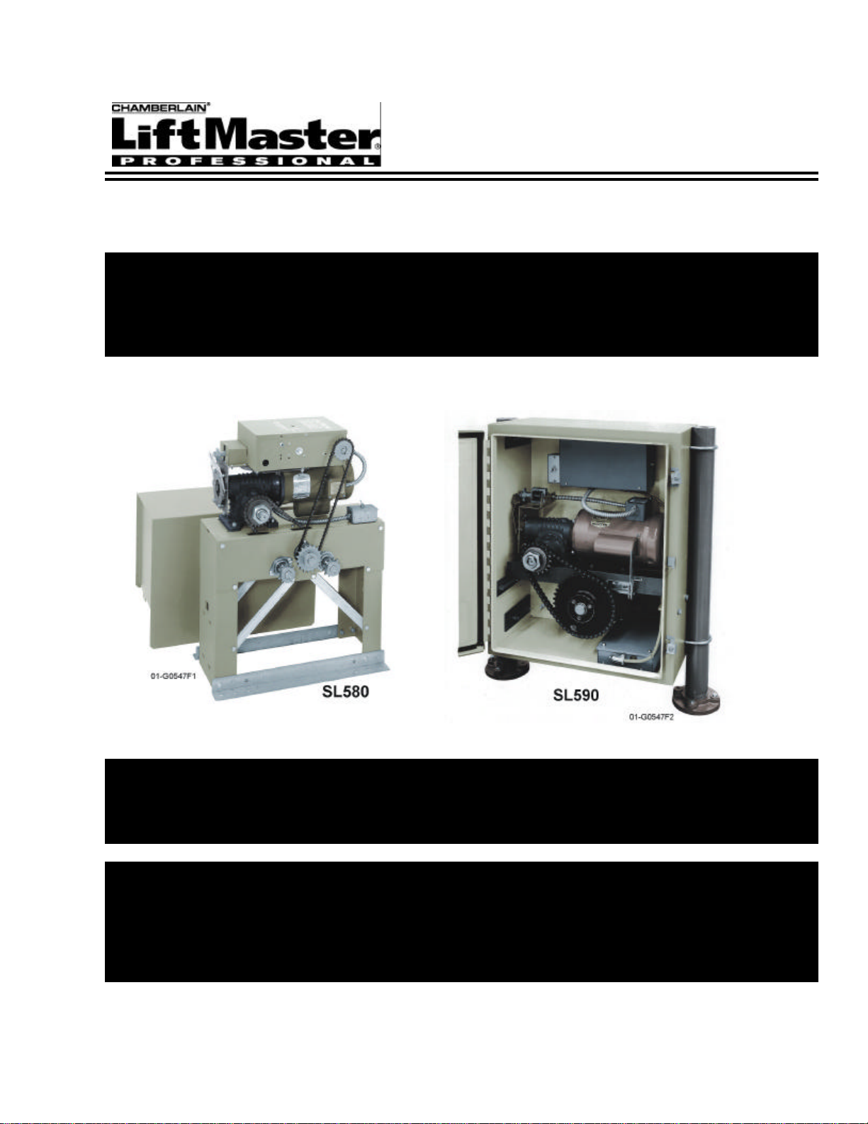
Model SL580
Heavy Duty Slide Gate Operator
Model SL590
Heavy Duty, Harsh Environment
Slide Gate Operator
Doc 01-G0547
Rev D
Page 2

2 Contents
Contents
General Information________________________________________________________ 4
Supplied Parts _______________________________________________________________________ 4
Model Classifications _________________________________________________________________ 4
Specifications _______________________________________________________________________ 5
Operator Dimensions__________________________________________________________________ 6
Cycle Rates _________________________________________________________________________ 6
Safety Information _________________________________________________________ 7
Safety Instructions____________________________________________________________________ 7
Safety Precautions for Open-Roller Gates and Ornamental “Grill Type” Gates ____________________ 9
Pre-Installation Check-List _________________________________________________ 11
Wiring Specifications ________________________________________________________________ 11
Features_________________________________________________________________ 13
Operator Features ___________________________________________________________________ 13
System Features_____________________________________________________________________ 15
Installation ______________________________________________________________ 17
Step 1: Set Up Post or Pad Mounting ___________________________________________________ 17
Step 2: Mounting the Operator________________________________________________________ 19
Step 3: Gate Brackets _______________________________________________________________ 19
Step 4: Drive Chain_________________________________________________________________ 20
Electrical Disconnect Switch___________________________________________________________ 21
Step 5: Electrical Power Connections ___________________________________________________ 21
Step 6: Limit Switch Adjustments _____________________________________________________ 22
Programming ____________________________________________________________ 23
Switch #1: Operator Programming ______________________________________________________ 23
Switch #2: Timer to Close_____________________________________________________________ 24
Adjustments and Check Out_________________________________________________ 25
Clutch Adjustment___________________________________________________________________ 25
Preliminary System Check Out_________________________________________________________ 25
Controls and Accessory Installation __________________________________________ 26
Doc 01-G0547
Rev D
Page 3

Contents 3
Troubleshooting___________________________________________________________27
1. Power___________________________________________________________________________ 27
2. Accessories ______________________________________________________________________ 28
3. Primary Voltage Circuit ____________________________________________________________ 28
4. Low Voltage Circuit _______________________________________________________________ 29
Gear Reducer _______________________________________________________________________ 30
General Reference Information_________________________________________________________ 30
Features and Program Troubleshooting Review____________________________________________ 30
Required Maintenance – Normal Usage _______________________________________31
SL580/590 Parts List & Drawings ____________________________________________32
SL580 Exploded View _______________________________________________________________ 32
SL580 Parts List ____________________________________________________________________ 33
SL590 Exploded View _______________________________________________________________ 35
SL590 Parts List ____________________________________________________________________ 36
Warranty Policy___________________________________________________________38
Doc 01-G0547
Rev D
Page 4

4 General Information
General Information
Supplied Parts
Inspect the operator for possible shipping damage and shortage of parts. Some ordered accessories
may be packed separately.
For Models SL580 & SL590
PART # DESCRIPTION QTY. PART # DESCRIPTION QTY.
01-G0547 SL580 & SL590 MANUAL 1 82-QN43-12
01-G0582 GATE SAFETY INSTR. 1 84-RH-50 1/2-13 HEX NUT 4
02-401-SP STOP BUTTON 1 84-WH-31
10-3209 GATE BRACKET 2 84-WH-38
11-3503 TAKE UP BOLT 2 85-FW-38 3/8 FLAT WASHER 8
19-3025 #50 CHAIN 1 85-FW-50 1/2 FLAT WASHER 4
80-3001 5/16-18 U-BOLT 4 85-LS-50 1/2 SPLIT LOCK WASHER 4
80-3002 3/8-16 U-BOLT 4 40-3505 WARNING SIGN 2
7/16-14 x 3/4 SQUARE
HEAD BOLT
5/16-18 SERRATED
FLANGED LOCK NUT
3/8-16 SERRATED
FLANGED LOCK NUT
4
8
8
Model Classifications
RESIDENTIAL VEHICULAR GATE
OPERATOR: CLASS 1
A vehicular gate operator or system intended
for use in a home of one to four single family
dwelling or a garage or parking area.
COMMERCIAL/GENERAL ACCESS
VEHICULAR GATE OPERATOR:
CLASS 2
A vehicular gate operator or system intended
for use in a commercial location or building
such as a multi-family housing unit of five or
more single family units, hotel, garages, retail
store, or other building servicing the general
public.
MODEL CLASS 1 CLASS 2 CLASS 3 CLASS 4
SL580
SL590
â â â â
â â â â
Table 1
INDUSTRIAL/LIMITED ACCESS VEHICULAR
GATE OPERATOR: CLASS 3
A vehicular gate operator or system intended for use
in an industrial location or building such as a factory
or loading dock area or other locations not intended
to service the general public.
RESTRICTED ACCESS VEHICULAR GATE
OPERATOR – CLASS 4
A vehicular gate operator or system intended for use
in a guarded industrial location or building such as
an airport security area or the other restricted access
location not servicing the general public, in which
unauthorized access is prevented via supervision by
security personal.
TYPES OF SLIDE GATES
These gate operators are intended t be used with slide gates of the following type: Track
mounted, overhead, cantilever, and track guided v-track.
Doc 01-G0547
Rev D
Table 2
Page 5

Specifications
General Information 5
Model H.P. Gate Speed
SL580 ½ 11”/sec. 1000 lbs. 25 ft. 45 ft. 35 ft.
SL580
SL580
SL580
SL590 ½ 12”/sec. 1100 lbs. 25 ft. 45 ft. 35 ft.
SL590
SL590
SL590
SL590
¾ 11”/sec. 1300 lbs. 30 ft. 60 ft. 45 ft.
1 11”/sec. 1600 lbs. 35 ft. 70 ft. 50 ft.
1-1/2 11”/sec. 1900 lbs. 40 ft. 80 ft. 60 ft.
¾ 12”/sec. 1400 lbs. 30 ft. 60 ft. 45 ft.
1 12”/sec. 1700 lbs. 35 ft. 70 ft. 50 ft.
1-1/2 12”/sec. 2100 lbs. 40 ft. 80 ft. 60 ft.
2 12”/sec. 2500 lbs. 45 ft. 90 ft. 70 ft.
Max. Gate
Weight
Max. Cant’l.
Width
Max. O/H
Width
Max. V-Track
Width
Table 3
Doc 01-G0547
Rev D
Page 6
6 General Information
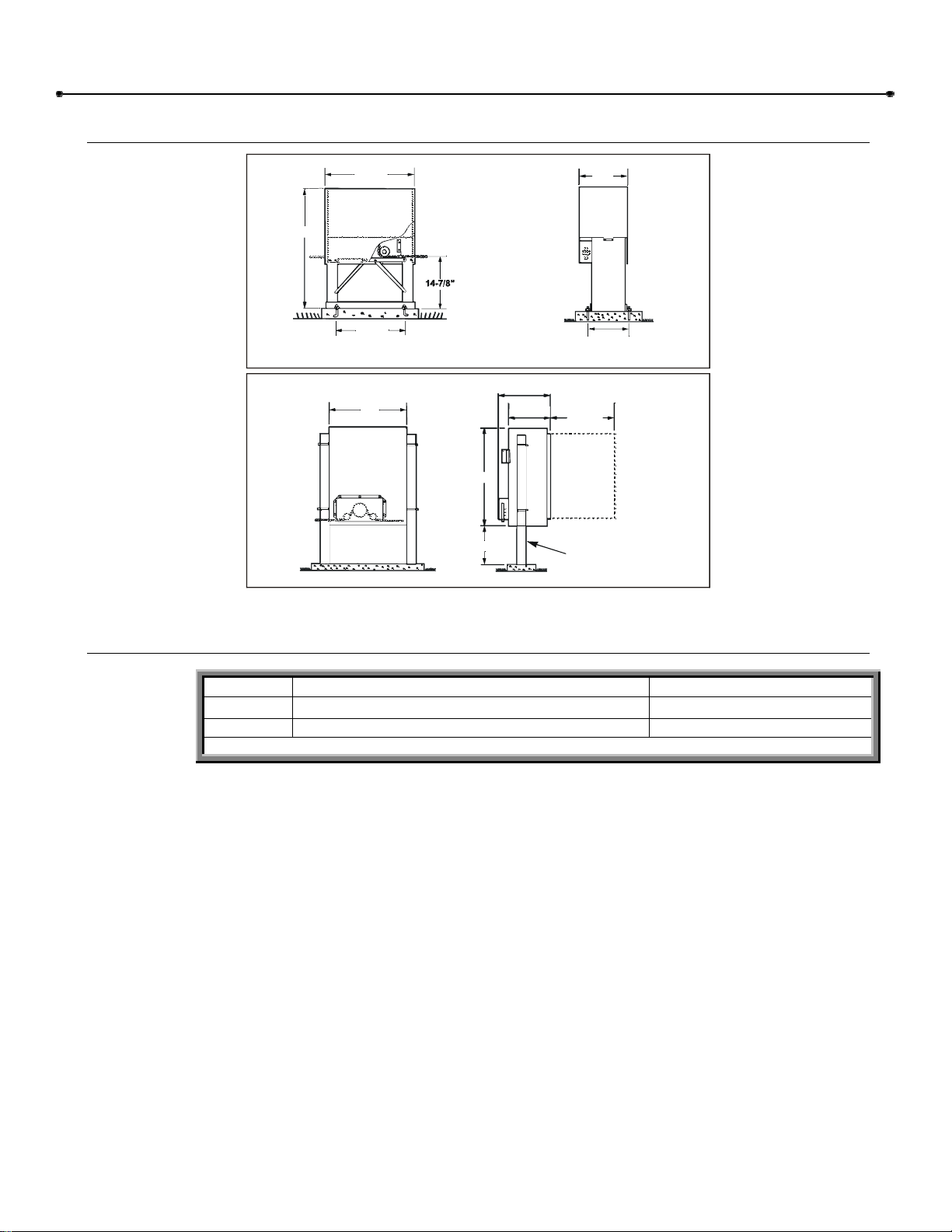
NOTE: Diagonal support braces shown are standard only on 1-1/2hp operators.
01-G0547F5
3” DIA. PIPE
(Not Supplied with Operator)
Operator Dimensions
MODEL SL580
34-3/4”
MODEL SL590
25-7/8”
21-1/8”
24”
30”
12” MIN.
Figure 1
16-1/2”
13-1/2”
13”
10-7/8”
22-1/2”
ALLOW FOR
DOOR
OPENING
Cycle Rates
â Cycle = One full open and one full close.
MODEL APPLICATIONS
SL580 Heavy Duty, Industrial
SL590 Heavy Duty, Industrial with Harsh Environment
Table 4
â CYCLE RATE PER HOUR
20
25
Doc 01-G0547
Rev D
Page 7

7 Safety Information
Safety Information
Vehicular gate systems provide convenience and security. Gate systems are comprised of many
component parts. The gate operator is only one component. Each gate system is specifically
designed for an individual application.
Gate operating system designers, installers and users must take into account the possible hazards
associated with each individual application. Improperly designed, installed or maintained systems can
create risks for the user as well as the bystander. Gate systems design and installation must reduce
public exposure to potential hazards.
A gate operator can create high levels of force, in its function as a component part of a gate system.
Therefore, safety features must be incorporated into every design. Specific safety features include:
Gate Edges Enclosed Track Vertical Posts
Guards for exposed
rollers
Screen Mesh
Important instructions follow. These instructions are intended to highlight certain safety related issues.
These instructions are not intended to be comprehensive. Because each application is unique, it is the
responsibility of the purchaser, designer, installer and end user to ensure that the total gate system is
safe for its intended use.
Photo-electric Sensors Instructional and
Precautionary Signage
Safety Instructions
Select instructions are highlighted with this precautionary symbol (see left margin). Failure to follow
these selected instructions can result in serious injury or death.
STEP 1: BEFORE INSTALLATION
1 Confirm gate operator model is specified by Installation and Maintenance Manual for
application type, gate size and frequency or use.
2 Confirm ALL appropriate safety features, such as gate edges, photo-electric sensors,
vertical posts and enclosed tracks, are specified.
3 Confirm gate system design reduces pinch points and protects against entrapment.
4 Confirm gate system design has pedestrian access separate from vehicular entrance.
5 Confirm gate system design reduces traffic backup.
6 Confirm warning signage is included in design.
7 Confirm gate moves freely before installation of operator
8 Repair or service worn or damaged gate hardware before installation of operator.
9 To avoid installation hazards, review the gate system operation and installation
10 Confirm control design prohibits unauthorized use.
Doc 01-G0547
Rev D
procedures, such as manual disconnect mechanism procedure.
Page 8

8 Safety Information
STEP 2: DURING INSTALLATION
1 Disconnect power at service panel before making any electrical connection.
2 Avoid pinch points, be aware of all moving parts.
3 Adjust clutch or load sensing device to minimum force setting.
4 Do not over-tighten cutch or adjust force setting above minimum.
5 Install controls where user cannot touch gate while operating controls.
6 Install controls where user has full view of gate operation.
7 Install two or more warning signs on the gate to alert persons in the area of automatic gate
operation. Warning signs must be conspicuous.
8 Install operator inside fence line. DO NOT install operator on public side of fence line.
9 Secure gate operator cover.
STEP 3: AFTER INSTALLATION
1 Test all safety features.
2 Train end user about basic functions and safety features of gate system.
3 Leave Installation and Maintenance Manual and Safety Instructions with end user.
Doc 01-G0547
Rev D
Page 9
Safety Information 9
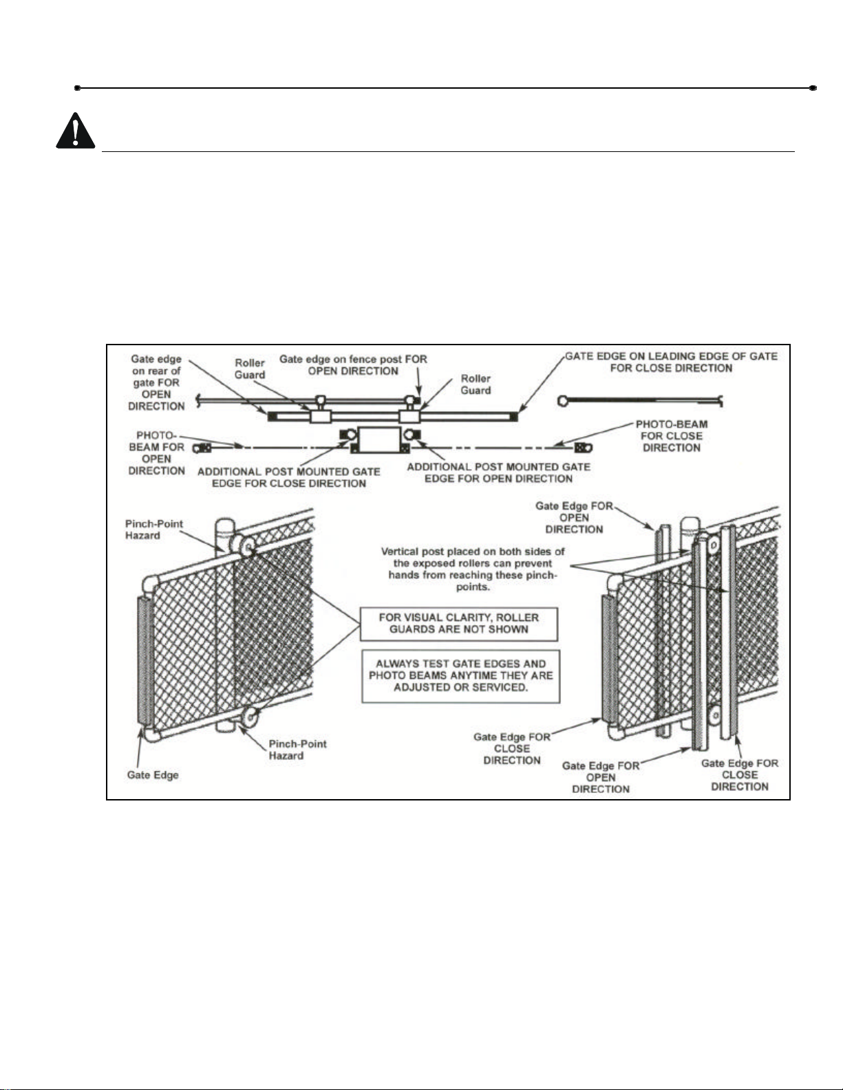
Safety Precautions for Open-Roller Gates and Ornamental “Grill
OPEN-ROLLER GATES
Injuries occur when people get their or feet caught between the top or bottom of the gate and the
gate roller. This potential pinch-point should be guarded against at all times. Enclosed style gate
tracks are available for refitting of these rollers from many fence suppliers. Also, roller guards are
available for installing over the rollers.
One more contact sensors shall be located at the leading edge, trailing edge, and post-mounted
both inside and outside of a vehicular horizontal slide gate.
Figure 2
Doc 01-G0547
Rev D
Page 10
10 Safety Information
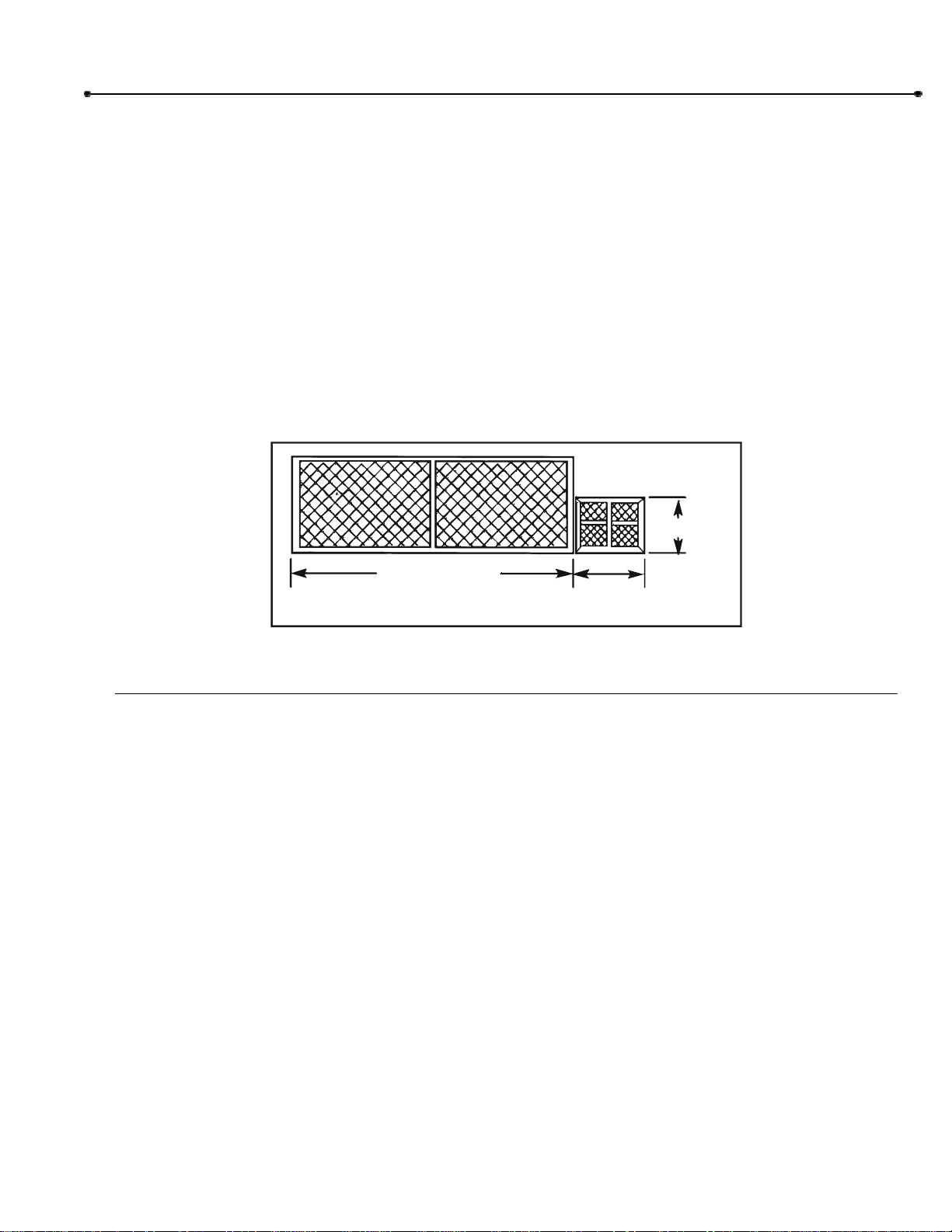
ORNAMENTAL “GRILL TYPE” GATES
Injuries occur when people put their hands and arms through openings in the grill and the gate is
operated. They cannot retract their arm and it gets caught between the moving gate grill and the
stationary fence post or fence. This potential hazard can be averted by placing a 4’ screen mesh
on the gate to prevent access through openings anywhere the gate may travel. See Safety
Brochure for details.
Figure 3
Doc 01-G0547
Rev D
Page 11
11 Pre-Installation Check-List
01-G0685F2
Pre-Installation Check-List
Φ Check the gate. It must operate smoothly and freely. If necessary, lubricate, adjust, or repair the
gate prior to operate installation. The gate must be level and plumb.
Φ Some gates may only be as wide as the gate opening. They may require a back frame to be
constructed to allow for chain attachments.
Φ Double check the size and weight of the gate to make sure that this operator is proper for this
application.
Φ If wiring has already been installed, check to make sure it meets the following specification and
requirements.
BACKFRAME
2 FT.
GATE OPENING
Figure 4
3 FT. MIN.
Wiring Specifications
Refer to Table 5.
A. The distances shown in Table 5 are measured in feet from the operator the power source.
B. These calculations are based on the National Electrical Code and allows for a 5% voltage
drop.
C. Supply voltage must be within 10% of the operator’s rating under load conditions.
D. There calculations are based on stranded copper wire.
E. It is highly recommended that only 90% of the distances shown be used; this will allow for a
10% safety factor.
F. For dual units, the distance shown should be cut in half.
G. Permanent wiring is to be employed as required by local codes.
Doc 01-G0547
Rev D
H. All local codes must be strictly adhered to. It is very important that operator is properly
grounded.
I. Do not run control wires in the same conduit with power wires.
J. Do not run multi conductor or parallel conductor cable for controls.
K. All power wiring should be dedicated and protected.
Page 12

12 Safety Information
WIRE
GAUGE
6
8
10
12
HP 115 VAC 230 VAC 230 VAC 460 VAC 575 VAC
1/3
1/2
3/4
1
1-1/2
2
1/3
1/2
3/4
1
1-1/2
2
1/3
1/2
3/4
1
1-1/2
2
1/3
1/2
3/4
1
1-1/2
2
Single Phase 3 Phase
684
473
324
237
158
-432
299
204
149
100
-271
187
128
94
62
-170
117
80
59
39
--
3,077
2,051
1,231
947
648
437
1,942
1,295
777
597
409
299
1,218
812,
487,
375,
256
187
763
509
305
235
161
117
4,737
2,842
2,030
1,421
947
711
2,990
1,794
1,281
897
589
448
1,876
1,125
804
563
375
281
1,175
705
503
352
235
175
14,211
14,211
7,105
5,684
4,060
2,842
8,969
8,969
4,484
3,587
2,562
1,794
5,627
5,627
2,814
2,251
1,608
1,125
3,524
3,524
1,762
1,410
1,007
705
35,527
17,764
11,842
8,882
5,921
4,441
22,422
11,211
7,474
5,605
3,737
2,803
14,068
7,034
4,689
3,517
2,345
1,758
8,810
4,405
2,937
2,203
1,468
1,101
Table 5
NOTE: Calculated using NEC guidelines. Local codes and conditions must be reviewed for suitability
of wire installation. Master/Slave units must be installed on separate circuits.
Control Wiring
Volt Max. Dist. (Ft.) Wire Gage
24 1000 18
Table 6
Doc 01-G0547
Rev D
Page 13

13 Features
SOLENOID
IMPORTANT: A clutch that is set too loose
Features
Operator Features
SOLENOID ACTIVATED, CALIPER
DISC BRAKE
The brake (Figure 5) minimizes overtravel
caused by gate coasting. An added
feature of the brake is to assist in
preventing backdriving of the gate.
The brake is spring applied whenever the
motor is not running. Anytime the motor is
running, the electric solenoid physically
releases the brake.
Important: periodically check and adjust
the brake mechanism. See page 31.
PRESSURE TYPE SLIPPING
CLUTCH
The operator clutch mechanism (Figure 6)
works similar to that of a clutch in a car. It
allows the operator to gradually start the
gate moving, rather than trying to
instantaneously start moving the gate.
BRAKE
BRAKE
01-G0547F6
Figure 5
CLUTCH
This clutch mechanism must be adjusted
properly. During the installation of the
operator, you must tighten the clutch
spring lock nut so it is tight enough to
operate the gate, yet loose enough so that
if the gate meets an obstruction, the clutch
will slip easily.
This clutch system will require periodic
maintenance. See page 31.
WARNING
This friction clutch system is not an automatic reversing device. It only serves to minimize
damage to the gate operator and gate, and also to hopefully minimize vehicle damage. If you
need an external automatic obstruction sensing device, items such as gate edges and photo
beams are available to help protect pedestrians.
Doc 01-G0547
Rev D
will give false inherent entrapment
and reverse or stop the gate.
Figure 6
01-G0547F7
Page 14

14 Features
G
0
5
4
7
F
8
MANUAL OPERATION
The gate cannot be moved manually when the operator drive mechanism is connected to it. To
disconnect the gate from the drive system, follow the directions below and refer to Figure 7.
DISCONNECT
SL580
SL590
0
1
-
Figure 7
MODEL SL580 – Slide out the lock bar located underneath the cover and remove the cover.
Pull the disconnect chain and engage it in the slot provided. The gate may now be moved
manually.
To re-engage the operator, release the chain from the slot. The lock bar has provisions for a
padlock to prevent tampering with the operator.
MODEL SL590 – Open the hinged door and pull the disconnect lever and lock it in place.
The gate may now be moved manually.
To re-engage the operator, release the lever and close the door. The door has provisions for
a padlock to prevent tampering with the operator.
NOTES: On both models, when the operator is under load, you may find it necessary to
relieve the tension on the drive chain before disengaging the system. This may be
accomplished by firmly applying pressure in a downward motion to the drive chain with
your foot. You may also relieve pressure by rotating the external gear reducer shaft,
extending through the brake.
Doc 01-G0547
Rev D
Manual Disconnect does not prevent motor from running.
Page 15

System Features
01-G0685F5
ACTIVITY LED
Features 15
Steady indication when gate is at
either open or close limit.
1 flash per second when gate is off
a limit in normal operation
2 flashes per second when
entrapment level one has occurred.
SL580 CONTROLLER
SHOWN
AUDIBLE WARNING DEVICE
If the operator should have a second
inherent obstruction in sequence with the
first; i.e. back to back, the sounder will
activate. Also the sounder can be
programmed to come on 2 seconds prior to
gate movement and stay on during gate
movement.
THREE BUTTON CONTROL (SEQUENCE OF
OPERATION)
Open, stop, close, close is programmable. Stop will override
all other functions. If closing, open will cause the operator to
stop and reverse to full open. Will close from open limit or
midstop only. If SW1 pin 1 is on three button station will only
close the operator from the open limit or from mid-stop. If
SW1 pin 1 is off, the input will work as a single button (open,
close, stop).
01-G0547F9
Figure 8
SWITCH #1
Figure 9
SINGLE BUTTON CONTROL (SEQUENCE OF OPERATION)
Open to open limit, close open. If power has been interrupted, will always open with first
activation.
CLOSE SINGLE BUTTON SELECT
The single button (programmable) control can be programmed to either function as a single button
control or to function as a close button only.
DIGITAL MICROPROCESSOR
This is the main circuit board for the operator. It contains all the logic and intelligence for the
system. All the system programming is done on this circuit board. All solid state, with an
emergency back-up system that works even if the processor is missing.
INHERENT OBSTRUCTION PROTECTION
The limit shaft is equipped with an R.P.M. sensor. When the gate meets an obstruction, the loss
of r.p.m’s. will cause the gate to reverse. A second obstruction will cause the gate to stop. A
renewed wired input will restart the gate.
Doc 01-G0547
Rev D
Page 16

16 Features
EXTERNAL OBSTRUCTION CIRCUIT
This circuit can be used with either a gate edge or a photo beam system. When either of the two
devices mentioned are activated, the operator will react in a similar manner to the inherent
obstruction described above.
SPECIAL NOTE ABOUT OBSTRUCTION SENSING FROM EITHER INTERNAL OR
EXTERNAL SYSTEMS
The operator will stop if it senses two sequential obstructions. If will not activate form any
automatic system, including the built in time delay to close. Either a manual device such as a
pushbutton within site of the gate and operator, or the stop button supplied with the operator must
be activated to resume the operator back to its normal operation.
OPEN ONLY CIRCUIT
Separate open circuits for line-of sight devices and out-of-sight devices such as open loops or
radio controls.
LOOP CONTROL CIRCUITS
Vehicle control devices such as opening or security loop detectors are connected to this circuit
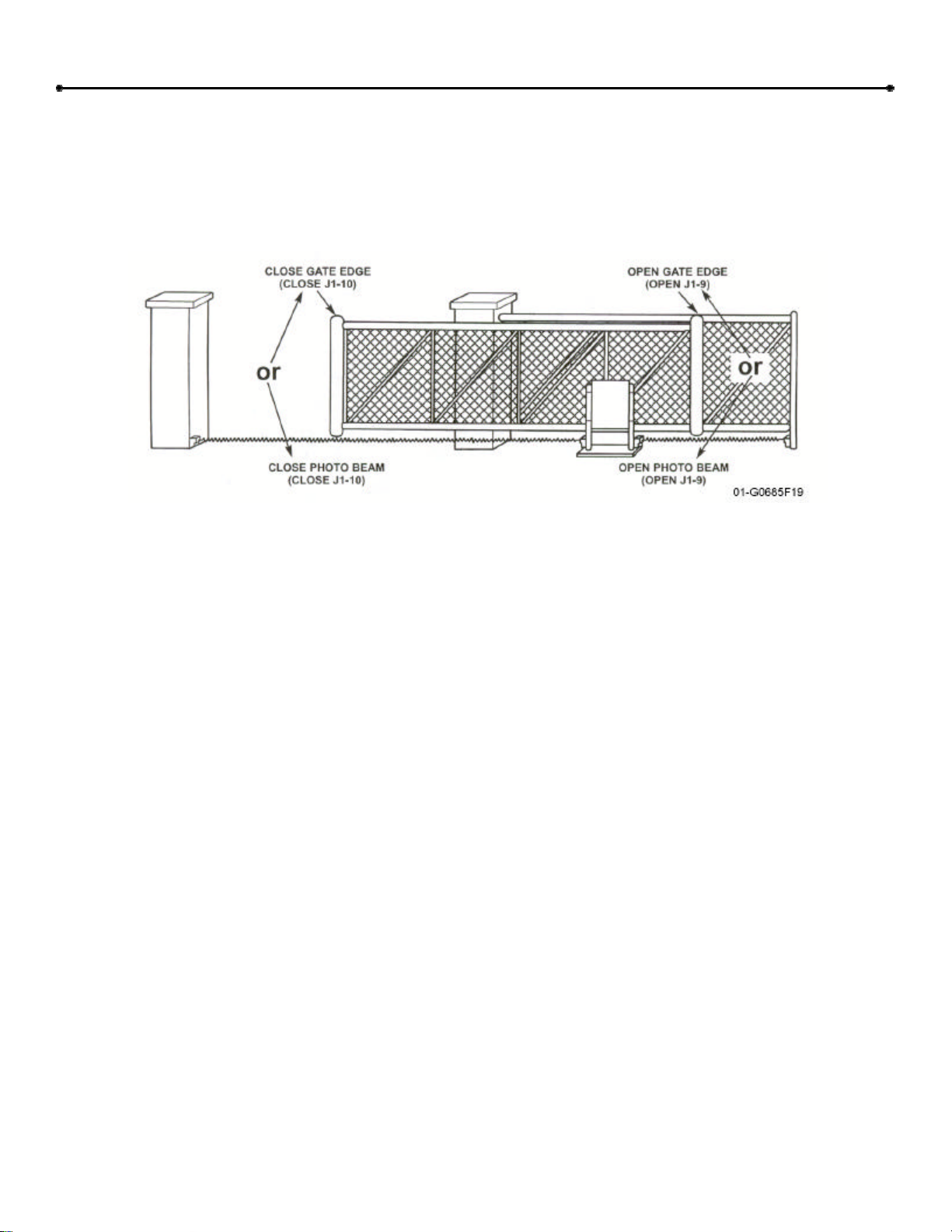
NOTE: If external entrapment protection is required by the class of operator, both an open
and closed protection device must be used.
TIME DELAY TO REVERSE CIRCUIT
Allows the gate to come to a complete stop before reversing direction. Approximately ½ second
between stop and reverse.
NOTE: This feature is defeated when either the inherent or external obstruction circuits
are activated.
Doc 01-G0547
Rev D
Page 17

17 Installation
REAR OF GATE
OR BACKFRAME
Installation
Please note that there are two basic types of power unit mounting, concrete pad or post mounting.
Choose the proper mounting for your application. The installation illustrations shown are for right hand
units; for left hand units, everything will be just the opposite.
If there is existing concrete at the area of power unit mounting, use the dimensioning procedure called
out in pad mounting instructions. It is suggested that ½” threaded anchors (not supplied) be used to
secure the unit. If needed, shim the unit to ensure that it is level and parallel with the gate.
Step 1: Set Up Post or Pad Mounting
CONCRETE PAD: SL580 ONLY
1 Layout concrete pad as detailed.
2 Locate electrical conduit, as required, prior to pouring concrete.
3 Pour concrete, insuring that pad is level and above the ground line.
4 Locate four (4) 1/2” threaded anchors, not supplied, as detailed. Important: Anchors
must be positioned accurately and securely in concrete.
5 Allow concrete to set for at least two days before installing power unit.
4-1/4”
10-7/8”
7-1/2”
1/2” MOUNTING BOLTS
OR ANCHORS
1” MIN.
2”-4”
FENCE LINE
21-1/8”
28”
REQUIRED BY
LOCAL CODES
3/4”
18”
DEPTH AS
OR BELOW
FROST LINE
Doc 01-G0547
Rev D
01-G0547F10
Figure 10
Page 18

18 Installation
REAR OF GATE
OR BACKFRAME
REAR OF GATE
OR BACKFRAME
POST MOUNTING: SL580 ONLY
1 Locate and secure two posts, 3” O.D.
heavy wall pipe.
2 Remove the mounting angles from base
of power unit. Use the angles to maintain
the proper distance between posts.
Secure the angles to the posts using Ubolts.
3 Check that:
FENCE LINE
9-1/2”
4-1/2” 24-1/8”
3” O.D.
ü Each post is the same distance
from the gate.
ü That the distance between the
posts is 24-1/8”.
ü The post height is at least 15” from
the ground.
ü Tops of posts are level with each
other.
4 Locate conduit, as required.
5 Allow concrete to set at least two days
before installing power unit.
POST MOUNTING: SL590 ONLY
1 Locate and secure two posts, 3” O.D.
heavy wall pipe.
2 Check that:
ü Each post is the same distance
from the gate.
DEPTH AS
REQUIRED
BY LOCAL
CODES OR
BELOW
FROST
LINE
8-3/4”
3” U-BOLTS
Figure 11
FENCE LINE
15” MIN.
01-G0547F11
ü That the distance between the
ü The post height is at least 42” from
ü Tops of posts are level with each
3 Locate conduit, as required.
4 Allow concrete to set at least two days
before installing power unit.
Doc 01-G0547
Rev D
posts is 24”.
the ground.
other.
DEPTH AS
REQUIRED
BY LOCAL
CODES OR
BELOW
FROST
LINE
7-1/2”
MIN.
Figure 12
24”
3” O.D.
42”-48”
01-G0547F12
Page 19

Installation 19
previously been located
Using the 3” U-bolts and
secure the operator to the
“OUTSIDE”
2” U-BOLTS
WITH LOCK-
Step 2: Mounting the Operator
For all mounting styles, it is very important that the operator is level and parallel to the gate.
PAD MOUNT: SL580 ONLY
After concrete has set, carefully secure
operator to the concrete pad with drive
and idler sprockets facing gate. The ½”
L-bolts will protrude through the holes in
the mounting flanges and should be
secured with lockwashers and hex nuts
(not provided).
POST MOUNT
After concrete has set, carefully secure
operator to the posts with drive and idler
sprockets facing the gate. Use the 3” Ubolts and hardware provided. Model
SL590: allow a minimum of 12” between
ground level and the bottom of operator.
PAD MOUNT DETAIL
Using suitable
hardware, secure the
operator mounting
flanges to the
L-bolts that have
in the concrete pad.
Figure 13
POST MOUNT DETAIL
GATE
hardware supplied,
mounting posts that have
previously been located
in the concrete pad.
◊
Model SL590 12” minimum
◊
from ground level.
Figure 14
GATE
01-G0547F13
01-G0547F14
Step 3: Gate Brackets
For steps 3 & 4, refer to Figures 15-17.
Secure gate bracket to the vertical front and rear
posts of the gate.
NOTE: If a back frame was added, then
secure rear gate bracket to the back frame.
Important: The large slotted holes in gate
brackets must be level and in line with the bottom
of the idler sprockets and each other. Slide the
gate to the full open and full closed positions to
check alignment.
GATE
BRACKET
SETSCREW
GATE
“INSIDE”
WASHERS &
NUTS
01-G0547F17
Figure 15
Doc 01-G0547
Rev D
Page 20

20 Installation
Gate brackets must be level and in line
01-G0547F18
INSERT CHAIN THROUGH PLASTIC GUIDES
Step 4: Drive Chain
1 If you have not already done so, remove the
operator cover.
2 Locate and engage the manual disconnect
lever and lock it in place. Refer to 14.
3 Connect one chain take-up bolt to the end of
the chain and attach to the rear gate bracket.
Refer to bracket detail below.
4 Ensure that the drive and idler sprockets are
in-line with each other. Thread the chain
through plastic chain guide, around drive and
idler sprockets, and then through the second
plastic chain guide toward front gate bracket.
CAUTION
When pulling the chain through the operator,
the limit shaft will turn. Do not drive the limit
(nuts) actuators on this shaft past their
normal positions.
5 Adjust the chain to proper length and attach
second take-up bolt to chain end. Secure the
take-up bolt to the front gate bracket as
shown.
◊
◊
with bottom of idler sprockets.
Figure 16
◊
Important: Check alignment of gate brackets
to idler sprockets in both vertical and
horizontal directions.
SAFETY BRACKET
01-G0547F19
Figure 17
6 Adjust nuts on chain take-up bolts to remove chain slack. Leave a maximum of one (1) inch
of chain slack for every 10 feet of chain length. Do not overtighten chain.
7 It is recommended that the gate brackets be welded to the gate after the chain is properly
installed, adjusted, and the operator is functioning.
SUGGESTION
To prevent excessive chain sag, LiftMaster recommends that you add some type of chain support
for gates over 20 feet in length. Please note that chain supports must be located a minimum of ¾”
below the idler sprocket shield and must note exceed ¾” beyond the centerline of the chain.
NOTE ABOUT SOME TYPES OF CANTILEVER GATES
With some cantilever gates over 20 feet long, you may need to add a brace along the length of the
gate to prevent the gate from bowing with chain is tightened. This may also be required on some
styles of gates that are constructed out of aluminum. Note that if positioned properly, this brace
can also be used as a chain support.
Doc 01-G0547
Rev D
Page 21

Installation 21
COVER
CONNECTIONS
01-G0547F21
BEFORE PROCEEDING PLEASE READ THIS
Electrical Disconnect Switch
Throughout the course of installation you will be required to disconnect electrical power. This can be
done by locating the electrical power disconnect switch and turning it on or off as desired.
MODEL: SL580
01-G0547F20
ELECTRICAL
DISCONNECT
SWITCH
Figure 18
Step 5: Electrical Power Connections
CAUTION
Make sure power is disconnected at the main power
source and at the operator’s electrical disconnect
switch before proceeding.
MODEL: SL590
WIRE NUT
Secure all electrical power connections inside the
power wiring compartment located on the outside end
of control panel. Use the electrical wiring diagram
POWER
CONDUIT
supplied with this unit.
Figure 19
All single phase operators will have – L1 (neutral), L2 (hot) and ground.
All three phase operators will have – L1, L2, L3 and ground.
It is very important that operator is properly grounded.
NOTE: Permanent wiring is to be employed as required by local codes.
Important: On the phase operators the power connections must be properly phased. If they are
phased wrong, the gate operator will run backwards. To correct this situation, disconnect power at
main power source and at the operator’s electrical disconnect switch. Then, reverse any two of the
three power leads.
Doc 01-G0547
Rev D
Page 22

22 Installation
Step 6: Limit Switch Adjustments
1 By using the mechanical disconnect, manually open the gate to its full open position (Note
direction of limit nut travel).
2 Remove control panel cover and locate the rotary limit switch assembly. Disengage the
retaining bracket from the limit nuts.
3 Depending on the “hand” of the operator, rotate the open limit nut until it makes contact with
the open limit switch lever and trips the open limit switch activation button.
4 Adjust the other limit nut so that it is near the open limit nut but not touching.
5 Manually close the gate to its full closed position.
6 Disengage the retaining bracket and rotate the close limit nut until it makes contact with the
close limit switch lever and trips the close switch.
7 Re-engage the retaining bracket into both limit nuts and also re-engage the mechanical
disconnect.
MODEL: SL580
LIMIT A
LIMIT NUT
RETAINING BRACKET
DIRECTION OF
GATE TO OPEN
RIGHT A B
LEFT B A
OPEN LIMIT CLOSE LIMIT
MODEL: SL590
LIMIT B
LIMIT B
RETAINING BRACKET
LIMIT NUT
LIMIT A
01-G0547F22
Doc 01-G0547
Rev D
Figure 20
Page 23

23 Programming
01-G0610F13
Programming
Figure 21
Switch #1: Operator Programming
POLE #1: SINGLE/CLOSE BUTTON
ON = Close button only
OFF = Open/Close button
POLE #2: RIGHT HAND / LEFT HAND
ON = Left Hand (gate will open to the left)
OFF = Right Hand (gate will open to the right—inside of
fence looking out)
POLE #3: WARNING DEVICE
ON = Warning device will turn on 3 seconds before gate
starts to move in either direction.
OFF = Warning device disabled.
POLE #4: MASTER/SLAVE – SINGLE UNIT
ON = Master or Single Unit
OFF = Slave Unit
RED LED INFORMATION
Figure 22
Continuous ON = Unit is on a limit.
Blinking 1 flash per second = Normal operation (gate travel or midstop).
Blinking 2 flashes per second = Entrapment level 1 (operator reverse to limit).
Doc 01-G0547
Rev D
Page 24

24 Programming
01-G0610F14
TOTAL TIME
POLE #1 POLE #2 POLE #3 POLE #4
ON ON ON ON DISABLED DISABLED
OFF ON ON ON 1 SEC. 4 SEC.
ON OFF ON ON 13 SEC. 16 SEC.
OFF OFF ON ON 26 SEC. 2 SEC.
ON ON OFF ON 40 SEC. 43 SEC.
OFF ON OFF ON 52 SEC. 55 SEC.
ON OFF OFF ON 65 SEC. 68 SEC.
OFF OFF OFF ON 78 SEC. 81 SEC.
ON ON ON OFF 104 SEC. 107 SEC.
OFF ON ON OFF 117 SEC. 120 SEC.
ON OFF ON OFF 129 SEC. 132 SEC.
OFF OFF ON OFF 141 SEC. 144 SEC.
ON ON OFF OFF 155 SEC. 158 SEC.
OFF ON OFF OFF 167 SEC. 170 SEC.
ON OFF OFF OFF 180 SEC. 183 SEC.
OFF OFF OFF OFF 194 SEC. 197 SEC.
WARNING
DEVICE
DISABLED
TOTAL TIME
WARNING
DEVICE
ENABLED
Table 7
Switch #2: Timer to Close
Timer to close is locked out at the factory. To activate the timer to close, follow steps below:
Figure 23
1 Move safety jumper from bottom two pins to top two pins. Then set time per the chart.
2 During normal operation, if the operator stops on a limit (except the close limit), or mid travel,
the operator will time out per the chart and automatically close.
3 To lock the timer to close program and disable, simply return the jumper to the bottom two
pins, or turn on all pins of SW#2.
IMPORTANT NOTE: When using master/slave, only set the time for the master operator.
The slave operator must be set to disabled position (all poles on).
Doc 01-G0547
Rev D
Page 25

25 Adjustments and Check Out
CLUTCH LOCATION
Adjustments and Check Out
Clutch Adjustment
An adjustable friction type clutch is standard on the models
SL580 and SL590. It is important that you properly adjust
the clutch to obtain proper operator performance.
1 Loosen the 3 set screws on the clutch nut.
2 Back off the clutch nut until there is very little tension
on the clutch spring.
3 Tighten the clutch nut gradually until there is just
enough tension to permit the operator to move the
gate, but will allow the clutch to slip if the gate is
obstructed.
When the clutch is properly adjusted, it should
generally be possible to stop the gate by hand
during travel.
4 Re-tighten a set screw on the clutch nut that is
directly over a flat portion of the shaft.
Figure 24
MODEL: SL580
01-G0547F23
CAUTION
The friction clutch is not an automatic reversing device. It
minimizes damage to the gate operator and gate. It can also
limit major vehicle damage, if adjusted properly. This
operator incorporates an internal obstruction sensor system,
but it is highly recommended that external obstruction
sensing devices such as gate edges or photo beams
systems be incorporated into the gate system to aid in the
protection of any possible pedestrian traffic. Periodic
inspection of the clutch system and all internal and external
sensor systems is required to ensure their proper operation.
MODEL: SL590
01-G0547F24
Figure 25
Preliminary System Check Out
Before adding any options, accessories or adaptations, it is highly recommended that you check out
the system and its programs. If you have not already done so, temporarily connect a three button
station to the operator. Test for proper open, stop and closing of the gate. Test the internal
obstruction sensor system. Test for proper operation of all programs that were programmed into the
system. Once everything checks out okay, then proceed to adding on the accessory items for this job
site.
NOTE: LiftMaster recommends that if more than one accessory item is used, after each one is
attached, check it for proper operation before adding the next.
Important: Make sure that the two (2) gate warning signs are secured to the gate. One on the
inside and one on the outside. They must be easily seen.
Doc 01-G0547
Rev D
Page 26

Controls and Accessory Installation26
GATE LOCK
provide UL secondary safety for persons. This
OPEN BUTTON
Note, on a second inherent obstruction, this
5
7
5
4
gate will stop. May defeat the timer to close.
9
10
CLOSE
3
5
13
14
11
11
12
12
Controls and Accessory Installation
See wiring diagram for more information. See p. 11 for wiring distances and wire gauge
information.
All inputs are normally open and momentary, except the stop (NC), and emergency close and
emergency open (constant pressure). The following instructions are based upon UL 325, dated March
of 1999 and include recommendations for significant increase in safety.
We strongly recommend that you follow the UL guidelines presented throughout the manual.
Installation device instructions – always follow the instructions provided by the manufacturer when
installing and adjusting any control device. If these instructions are contrary to the advice given here,
call for assistance.
5 6
SUPERVISED
(WIRELESS) UNSUPERVISED
OPEN BUTTON
Caution - Only wired devices in sight of the
gate may be used with this input.
Any device can be used here and the radio
(R2) is wired here internally by the factory.
input will not function (disabled).
CLOSE/SINGLE BUTTON
OPEN
5
EXTERNAL ENTRAPMENT OPEN
Will reverse (close) the gate if active. If
entrapment is sensed during a reversal, the
5 8
INTERRUPT LOOP
This input is for vehicles only and does not
functions as an wireless open unless on the
close limit where it is defeated - thus preventing
R1
R2
R3
C
A
V
4
2
vehicles from entering freely.
TERMINAL STRIP
ON SIDE OF
1 2 3
RADIO
RECEIVER
CONTROL PANEL
SECONDARY SAFETY
It is recommended that secondary
safeties always be used for both
the open and close directions.
Use safety edges. In
the
device must sense people.
Loops cannot be used.
3
These are constant pressure inputs that
bypass the processor and may be used only
in an emergency if the processor fails.
Note left/right switch does not effect direction.
MASTER/SLAVE
Use shielded twisted pair.
do not run with power wiring.
any case,
1
E- OPEN
2
E- CLOSE
5
EXTERNAL ENTRAPMENT CLOSE
Will reverse (open) the gate if active. If
entrapment is sensed during a reversal the
gate will stop. May defeat the timer to close.
STOP BUTTON
- REQUIRED -
This is a normally closed input and the operator
will not run unless this is installed!
POWER
USE POWER TO MATCH GATE LOCK
REQUIREMENTS, NOT TO EXCEED
115V 10A.
For warning devices,
call the factory
01-G0665F19
Figure 26
NOTE: Numbers shown inside a box are on the J1 terminal strip on the circuit board.
Connections shown here are field connections. The radio receiver may be ordered factory
installed.
Doc 01-G0547
Rev D
Page 27

27 Troubleshooting
Troubleshooting
When troubleshooting, one of the first things to do is try to isolate the problem area. The four (4) main
areas to check out are:
Power
Accessories
Operator’s Primary Voltage
Operator’s Low Voltage
1. Power
Always use extreme caution! Some possible symptoms of power problems include:
The obvious one is – the operator will not run.
The operator runs slow.
Circuit breakers or fuses keep tripping.
Motor overload keeps tripping.
Operator starts but then stops
1A.
Using a V.O.M. take a voltage reading at the control transformer’s primary terminals. You should
get a reading as follows:
Nominal Volt. Min. Max.
120v. 108 132
230v. 207 253
460v. 414 506
Table 8
If you get a reading that does not fall into the minimum/maximum area, then check out your main
power supply. Also, make sure that the operator was ordered with the proper voltage and phase.
Another item to check is the wire run from the power supply to the operator. Double check the
gauge of the wire versus the distance.
1B.
If the voltage reading is O.K. from 1A, then take the same voltage reading with the operator
running. If voltage drops below the minimum with this reading, then there could be an excessive
current draw somewhere.
1C.
In some cases, power drops can occur at only specific times during the day or night. This can be
caused by increased power demands in a general area at a specific time.
Doc 01-G0547
Rev D
Page 28

28 Troubleshooting
2. Accessories
Add-on accessories can create many of the problems that are credited to the operator. Many
applications have more than one accessory item attached to the operator and some of these items
even draw their power from the operator.
Some of the symptoms that can show up because of accessories:
The operator won’t close.
The operator won’t open.
The operator will not run.
The operator begins to run then stops or reverses.
2A.
Whenever the problem is thought to be an accessory and there are more than one connected to
the operator, always disconnect one accessory at a time and then test the system. This will
hopefully isolate which item is causing the problem.
2B.
If an accessory item is being used as an access control device (used to open or close), falls in the
closed position or sends out a continuous signal. The operator will hold the gate in one position
until the signal from the accessory is removed.
2C.
In some applications, the gate may begin to move then either stop or stop and reverse within a
couple of seconds. This can be caused by an external obstruction device that has failed.
2D.
If there are many accessories attached to and powered by the operator, there may be too much
current draw for the operator’s control transformer. This operator can only supply approximately 2
amps @ 24 vac. Double check all accessories for their current requirements.
3. Primary Voltage Circuit
Use extreme caution when troubleshooting the primary voltage circuit! There are three (5) items
in this circuit that could be causing trouble, and they are:
Motor
Transformer
Brake solenoid
Contactor
Power disconnect switch
3A.
The first thing to check is the incoming power. Is it there at the incoming side of the power
disconnect switch?
Doc 01-G0547
Rev D
Page 29

Troubleshooting 29
3B.
If there is power, then check for it at the transformer primary terminals. If there is voltage at the
switch and none at the transformer, then you probably have a bad power disconnect and it should
be replaced.
3C.
If 3A and 3B check out O.K., then manually disconnect the operator from the gate. Very
carefully, using a screwdriver with an insulated handle, press down on the open side of the
contactor. Then, do the same to the close side of the contactor. Then, do the same to the close
side of the contactor. Did the operator run in both directions? If it did, the problem may be in the
low voltage control circuit, if it did not, then the problem is either in the contactor or the motor.
NOTE: Some motors have the overload built into the motor itself, while other units have a
separate overload in the controller.
3D.
If the contactor is suspected to be causing the problem, first carefully check all wiring connections
at the contacts. DISCONNECT POWER! USING A V.O.M. take continuity readings across the
contacts of the contactor. Place one probe on 1 and the other on 2. You should get NO
continuity, now press down on the contactor, you should get a continuity reading. Repeat this on
all the of the contactor’s contact points.
Figure 27
4. Low Voltage Circuit
4A.
The first thing to check is the circuit breaker.
4B.
The secondary voltage must be between 22 and 30 vac. This voltage can be checked at the
circuit board at terminals J1-3 & J1-11.
4C.
The contactor coils receive 24 vac. to activate the motor in either the open or close direction.
There are two contactor coils (one for open and one for close).
4D.
The limit switches are S.P.D.T. (single pole, double throw). These limit switches are what tells the
operator to shut off at either the full open or full close position.
Doc 01-G0547
Rev D
Page 30

30 Troubleshooting
4E.
The R.P.M. Sensor is counting the r.p.m ‘s of the wheel that is attached to the shaft. There are no
repairable parts for the sensor of wheel. The only thing that should be checked is the wire
harness. Make sure that the wires are crimpled and fully seated into the housing. Also make sure
that the housing is fully seated into the circuit board.
4F.
The circuit board is the “brains” of the entire system. It is a non-repairable item. In many cases,
un-awareness of the different programs and their functions can make it look like there is a
problem when in actuality it is just a missed or wrong program setting. Make sure that all the
connections wires on the “J1” terminal board are installed correctly. There MUST also be a stop
button connected to J1-3 and J1-5.
Gear Reducer
If physical signs show a seal has broken in the gear reducer, it may be necessary to replace
the reducer.
When replacing the gear reducer oil, use Mobil SHC 630 or equivalent. The oil level for the
gear reducer allows gear to be dipped but not submerged in oil.
Do not overfill gear reducer oil reservoir. Reducer oil – Part #04-DUP220HT
General Reference Information
THE GATE
Double check the gate and its related hardware. Does the gate move freely? If it doesn’t, this can
affect the internal obstruction sensor.
WIRING DIAGRAM
Always reference the wiring diagram that was supplied with the operator. Note that some of the
accessory items may have their own wiring diagram.
If you cannot correct the problem or if you feel you will require technical assistance, contact your
local distributor or dealer. If you do not have a distributor or dealer, then contact us for technical
assistance. Please when calling for assistance, make sure you have the gate operator model
number, voltage, phase, horsepower and a list of all accessories that are attached to the operator.
Features and Program Troubleshooting Review
The internal obstruction sensor (r.p.m. sensor) will cause the operator to either stop or reverse if it
senses a slow down in gate speed. A damaged or poorly working gate can trip the sensor and cause
“phantom” reversing or stopping. Also if the operator’s clutch is slipping too much, this can cause the
same situation.
Doc 01-G0547
Rev D
Page 31

31 Required Maintenance – Normal Usage
Complete Check Out
Required Maintenance – Normal Usage
Check at least once every
1
month3months6months12months
Internal speed
sensor
External safety
systems
Gate caution signs
Clutch systemá
Brake system Check & adjust if required
Manual disconnect Check & operate
Drive chain (D) (E)
Sprockets & pulleys
Gate Inspect for wear or damage
Accessories
Electrical Inspect all wire connections
Frame bolts Check for tightness
Total unit Inspect for wear or damage
Check for proper operation
Check for proper operation
Make sure they are present
Check & adjust if required
Check for excessive slack &
lubricate
Check for excessive slack &
lubricate
Check all for proper
operation
á
á
á
á
á
á
á
á
á
á
á
á
Table 9
áá Important: A clutch that is set too loose will give false, inherent entrapment and reverse
or stop the gate.
NOTES:
A. Caution: When servicing, always
disconnect operator from electrical power
supply.
B. Severe or high cycle usage will require
more frequent maintenance checks.
C. Inspection and service should always be
performed anytime a malfunction is
observed or suspected.
D. Limit switches may have to be reset after
any major drive chain adjustments.
E. If lubrication chain, use only a proper
chain lub spray or a lightweight motor oil.
Never use grease or silicone spray.
F. When servicing, please do some “home
cleaning” of the operator an the area
around the operator. Pick up any debris in
the area. Clean the operator if needed.
G. It is suggested that while you are at the
site, you take some voltage readings of
the operator. Using a VOM, double check
the incoming voltage to the operator to
make sure it is within ten percent of the
operator’s rating.
H. While you are at the site, now would be a
good time to let the owner or manager
know about any new items available or
any safety items that could and should be
added to the site.
Doc 01-G0547
Rev D
Page 32

SL580/590 Parts List & Drawings 32
SL580/590 Parts List & Drawings
SL580 Exploded View
Figure 28
Doc 01-G0547
Rev D
Page 33

SL580/590 Parts List & Drawings 33
SL580 Parts List
Part No. Qty. Description Part No. Qty. Description Part No. Qty. Description
02-401-SP (N) 1 STOP BUTTON 15-9020 2 50B12 SPROCKET 82-HN38-16 (N) 2 3/8-16 x 1 HEX BOLT
03-8024 1 24V REVER. CONTACT. 18-10036 (N) 2 DEPRESS PLATE SPRING 82-HN38-18 (N) 4 3/8-16 X 1-1/4 HEX BOLT
03-ABDIN-4 1 DIN RAIL 18-10194 4 .875L COMPRESS. SPRING 82-HW25-06T (N) 2 1/4-20 x 3/8 HEX BOLT
07-10179 1 BRAKE HUB 18-10467 1 COMPRESSION SPRING 82-HX10-08T (N) 18 10-32 x 1/2 HEX SCREW
07-11418 1 DISCONNECT 18-511 1 DISCONNECT SPRING 82-NH25-06CP (N) 6
07-5514 1 PRESSURE PLATE 18-5514 4 3" BELL WASHER 82-NH31-06CP (N) 7 5/16-18 x 3/8 SET SCREW
07-5515 2
10-10181 (N) 1
10-10190-C 1
10-10191 1 DISC BRAKE 19-48001 (N) 1 #48 CHAIN 82-PX06-16 (N) 2
10-10707 2
10-11045 1 EBOX MTNG. BRACKET 19-5040 1 #40 CHAIN MASTER LINK 82-PX08-04T (N) 10
10-3209 2 GATE BRACKET 19-9010-2 1 8A SASH CHAIN 82-PX08-06G (N) 1
10-3501-B 1 GSL CHASSIS 19-9024-NP 1 #50 CHAIN MASTER LINK 82-PX08-08 (N) 2
10-3502-B 2 LEG CHANNEL 23-2016 2 LIMIT SWITCH N.C. SPST 82-PX08-08T (N) 2
10-3503-B 1 GSL BOTTOM COVER 28-G0518 1 CONDUIT BOX 82-PX08-10T 5
10-3504-B 2 MOUNTING ANGLE 29-09028-2 1 TERM. BOARD FOR RADIO 82-QN43-12 4
10-3505-T (N) 1 COVER 29-18200 1 HALL EFFECT SENSOR 82-SH10-14 (N) 2 10-32 x 7/8 SCREW
10-3509-B 1 STIFFENER 79-18142 1 HALL EFFECT PCB 83-HS08-04 (N) 4 #8 SHEETMETAL SCREW
10-3510 1 CHAIN GUARD 29-18163 1 16 POLE MAGNET 84-LH-06 (N) 2 6-32 LOCK NUT
10-3511-B 1 LOCKING BAR 29-G0537 (N) 1 HIGH OUTPUT ALARM 84-RH-50 (N) 4 1/2-13 HEX NUT
10-3512 1 BAR GUIDE 310-84JH150 1 1-1/2-12 HEX JAM NUT 84-WH-25 (N) 12
10-3515 2 RETAINER GUIDE 31-10186 2 .20 ID x .31 l SPACER 84-WH-31 (N) 28
10-3522 2 REDUCE SHIM 31-113 (N) 4 LIMIT SWITCH SPACER 84-WH-38 (N) 26
10-3523 1 DISCONNECT LEVER 31-10024 2 1/2-20 LIMIT NUTS 85-FW-06 (N) 2 #6 FLATWASHER
10-3526-B 1 CONTROL BOX 32-10540 1 GEAR REDUCER 85-FW-08 (N) 4 #8 FLAT WASHER
10-3527 1 BRACKET LOOP 39-10182 4 BRAKE PAD 85-FW-25 (N) 4 1/4 FLATWASHER
10-3528-B (N) 1 ELEC. BOX COVER 39-5504 2 CLUTCH DISC 85-FW-31 (N) 2 5/16 FLATWASHER
10-10185 1 BRAKE PLATE 41-G0538 (N) 1 S3 ALARM SPACER 85-FW-38S (N) 17
10-5207 1 BRAKE SOL. COVER 42-8116-1 1 16 POS. TERM. BLOCK 85-FW-50 (N) 4 1/2 FLATWASHER
10-7020 1
10-7022 1 DEPRESS PLATE 69-G2000 1 S3 PCB ASSEMBLY 85-LS-10 (N) 2 #10 LOCKWASHER
10-9011 1 BEVEL RELEASE YOKE 71-416-7NH 1 24V LOOP BOARD (OPTL.) 85-LS-31 (N) 1 5/16-18 SPLI. LCKWSHER
10-G0326 1 SWITCH BOX COVER 74-G0487-M 1 HALL EFFECT SENSOR 85-LS-38 (N) 4 3/8 SPLIT LOCKWASHER
10-G0483 (N) 1
11-3501 1 DRIVE SHAFT 75-075514 (N) 1 CLUTCH 86-CP04-112 (N) 3 1/8 x 1-3/4 COTTER PIN
11-3502 2 IDLER SHAFT 76-G0537 1 ALARM ASSEMBLY 86-DP10-16 (N) 2 5/16 x 1 DOWL PIN
11-3503 2 TAKE-UP BOLT 80-207-19 3 1/4 x 1-1/2 KEY 86-RP04-100 (N) 1 1/8 DIA x 1" L ROLL PIN
11-3505 1 SHAFT DISC 80-207-35 2 1/4 x 1/4 x 1 KEY 87-E-038 (N) 1 3/8 E-RING
11-3506 1 DISCONNECT HANDLE 80-207-36 1 1/4 x 1/4 x 1-1/4L DIS. KEY 87-E-100 1 E-RING
11-5206 4 SPRING CUP 80-3001 (N) 4 5/16-18 U-BOLT 87-P-062 (N) 1
11-5207 4 BRAKE STUD 80-3002 (N) 4 3/8-16 U-BOLT 91-G0142 1 BRAKE PLATE ASSEMBLY
11-G0484 (N) 1 LIMIT SHAFT 80-5001 (N) 1 3/16 x 3/16 x 1-3/4L KEY 91-G0143 1
12-3534 (N) 1 SLEEVE BEARING
12-4164 6
12-5516 (N) 1 BEARING 82-CB31-26 (N) 4 5/16-18 x 2-1/2 CARR. BOLT 91-G0530 1 LIMIT SHAFT ASSEMBLY
12-9031 2 LIMIT SHAFT BEARING 82-CB38-24 (N) 4 3/8-16 X 2 CARRIAGE BOLT 15-5514 1
13-3510 4 CHAIN GUIDE 82-FX25-20 (N) 4 1/4-20 X 1-1/2 FH SCREW MG6400103 (N) 1 #8 EX. TOOTH WASHER
15-3516 1 50B16 SPROCKET 82-HN25-08 (N) 4 1/4-20 x 1/2 HEX H. BOLT MG6400104 (N) 1 #10 EX. TOOTH WASHER
15-3534 (N) 1 40B34 SPROCKET 82-HN25-12 (N) 4 1/4-20 x 3/4 HEX H. SCREW
15-48B18LGE
(N)
15-9014 (N) 1 48B18 SPROCKET 82-HN38-12 (N) 14 3/8-16 x 3/4 HEX BOLT
PRESSURE PLATE
GT&GSL REV A
BRAKE MOUNTING
PLATE
BRAKE RELEASE
LEVER
DISCONN. SUP.
BRACKET
S2 BRD. MNTG.
BRACKET
SENSOR MNTG.
BRACKET
SELF-ALIGN. FLANGE
MNT.
1 48B18 SPROCKET 82-HN31-16 (N) 8
19-3025 1 #50 CHAIN 82-PX04-04 (N) 2
19-3501 1 #40 CHAIN 82-PX06-06 5
19-3502 1 LIMIT CHAIN 82-PX06-06T (N) 2
19-48ML 1 #48 CHAIN MASTER LINK 82-PX06-19 (N) 4
42-G0509 1 TERM. BLOCK 7 POSITION 85-LS-06 (N) 2 #6 LOCKWASHER
75-075502 1 DISCONNECT KIT 85-LS-50 (N) 4 1/2 SPLIT LOCKWASHER
81-21CGS00600
(N)
82-CB31-16 (N) 6 5/16-18 x 1 CARR. BOLT 91-G0384 1
1 6" PLASTIC CARD GUIDE 91-G0146 1 LIMIT SPROCKET
5/16-18 x 1 HEX HEAD CAP
SCREW
Parts designated (N) are not shown on drawing.
Parts having one or more X in the part No. vary from model to model. See “Variable parts” below.
Parts designated (3PH) are present on 3 ph operators only.
Quantities shown in parenthesis are used only on 1 and 1 ½ HP operators.
1/4-20 x 3/8 CONE POINT
SET SCREW
4-40 X 1/4 PAN HEAD
PHILLIPS SCREW
6-32 x 3/8 SELF TAPPING
SCREW
6-32 x 3/8 SELF TAPPING
SCREW
6-32 x 1 PAN HEAD PHILLIP
SCREW
6-32 x 1-3/8 PAN HEAD
PHILLIP SCREW
8-32 x 1/4 SELF TAPPING
PHILLIP SCREW
8-32 x 3/8 PAN HEAD GREEN
SCREW
8-32 x 1/2 PAN HEAD
PHILLIP SCREW
8-32 x 1 SELF TAPPING
PHILLIP SCREW
8-32 x 5/8 SELF TAPPING
PHILLIP SCREW
7/16-14 x 3/4 SQUARE HEAD
SET SCREW
1/4-20 SERRATED FLANGED
NUT
5/16-18 SERRATED
FLANGED LOCK NUT
3/8-16 SERRATED FLANGE
NUT
13/16 OD x 13/32 ID
FLATWASHER
SELF-LOCKING EXT.
RETAINING RING
DISCONNECT SPROCKET
ASSEMBLY
BRAKE PRESSURE PLATE
ASSEMBLY
TORQUE LIMITER
SPROCKET ASSEMBLY
Doc 01-G0547
Rev D
Page 34

34 SL580/590 Parts List & Drawings
SL580 Variable Parts
Variable P/N Description Used On
20-XXXX 20-1050-T MOTOR: 1/2 HP - 115/230VAC - 1Ø - 60hz SL580-50-11-S3, SL580-50-21-S3, SL580-50-81-S3
20-1075-T MOTOR: 3/4 HP - 115/230VAC - 1Ø - 60hz SL580-75-11-S3, SL580-75-21-S3, SL580-75-81-S3
20-1100-T MOTOR: 1 HP - 115/230VAC - 1Ø - 60hz SL580-100-11-S3, SL580-100-21-S3, SL580-100-81-S3
20-3050-T MOTOR: 1/2 HP - 208/230/460VAC - 3Ø - 60hz SL580-50-23-S3, SL580-50-43-S3, SL580-50-83-S3
20-3075C-4T MOTOR: 3PH 3/4HP CFC 230/460VTEFC SL580-75-23-S3, SL580-75-43-S3, SL58-75-83-S3
20-3100M-5T MOTOR: 1 HP - 575VAC - 3Ø - 60hz SL580-100-53-S3
20-3100-T MOTOR: 1 HP - 208/230/460VAC - 3Ø - 60hz SL580-100-23-S3, SL580-100-43-S3, SL580-100-83-S3
20-3200-5T MOTOR: 2 HP - 575VAC - 3Ø - 60hz SL580-150-53-S3
20-3200C-4T MOTOR: 2 HP - 208/230/460VAC - 3Ø - 60hz SL580-150-23-S3, SL580-150-43-S3, SL580-83-S3
21-XXXX 21-3260 24V TRANSFORMER, 50VA ALL 115/230/208VAC - 1Ø and 208/230/460VAC - 3Ø MODELS
21-10298 24V TRANSFORMER, 100VA ALL 575VAC - 3Ø MODELS
22-XXX 22-120 120VAC BRAKE SOLENOID ALL 115VAC - 1Ø MODELS
22-240 230VAC BRAKE SOLENOID ALL 208/230/460VAC - 1Ø and 3Ø MODELS
22-575-1 575VAC BRAKE SOLENOID ALL 575VAC - 3Ø MODELS
23-XXXX 23-3001 POWER LINE SWITCH ALL 1Ø MODELS
23-3005 POWER LINE SWITCH ALL 3Ø MODELS
24-XXXX 24-115-1 115VAC RELAY ALL 115VAC - 1Ø MODELS
24-230-5 208/230VAC RELAY ALL 208/230VAC - 1Ø MODELS
25-XXXX 25-2006 6A FUSE SL580-50-21-S3, SL580-50-81-S3, SL580-75-81-S3
25-2008 8A FUSE SL580-75-21-S3
25-2010 10A FUSE SL580-50-11-S3, SL580-100-21-S3, SL580-100-81-S3
25-2015 15A FUSE SL580-75-11-S3, SL580-150-21-S3, SL580-150-81-S3
25-2020 20A FUSE SL580-100-11-S3
25-2025 25A FUSE SL580-150-11-S3
25-4002-5 1.6 - 2.5A FUSE SL580-75-53-S3, SL580-100-43-S3, SL580-100-53-S3
25-4004 2.5 - 4.0A FUSE SL580-150-43-S3, SL580-150-53-S3
25-4006 4.0 - 6.0A FUSE SL580-100-23-S3, SL580-100-83-S3
25-4008 5.5 - 8.0A FUSE SL580-150-23-S3, SL580-150-83-S3
Doc 01-G0547
Rev D
Page 35

SL590 Exploded View
SL580/590 Parts List & Drawings 35
Figure 29
Doc 01-G0547
Rev D
Page 36

36 SL580/590 Parts List & Drawings
SL590 Parts List
Part No. Qty. Description Part No. Qty. Description Part No. Qty. Description
02-401-SP (N) 1 STOP BUTTON 15-3619 1 50B19 SPROCKET 82-HN25-08 (N) 8 1/4-20 x 1/2 HEX HEAD BOLT
03-8024 1
03-ABDIN-4 1 DIN RAIL 15-48B9A1 (N) 1 48B9 SPROCKET 82-HN25-18 (N) 4 1/4-20 X 1-1/4 HEX HEAD BOLT
07-10179 1 BRAKE HUB 15-5514 1
07-3611 1 DISCONNECT BUSHING 15-48B18QGH 1 48B18 SPROCKET 82-HN38-16 (N) 27 3/8-16 x 1 HEX HEAD BOLT
07-5514 1 CLUTCH 18-10194 6 COMPRESSION SPRING 82-HN38-18 (N) 4 3/8-16 X 1-1/4 HEX HEAD BOLT
07-5515 2 PRESSURE PLATE 18-3601 1 DISCONNECT SPRING 82-HN50-16 (N) 1 1/2-13 x 1 HEX HEAD BOLT
10-10181 (N) 1
10-10190-C 1 BRAKE RELEASE LEVER 19-3025 1 #50 CHAIN 82-HX10-08T (N) 9 10-32 x 1/2 HEX HEAD SCREW
10-10191 1 DISC BRAKE 19-4071 1 #40 CHAIN
10-10707 2
10-3209 2 GATE BRACKET 19-5001 1 #48 LIMIT CHAIN 82-PX04-04 (N) 2
10-3515 2 GUIDE RETAINER 19-5040 1 #40 MASTER LINK 82-PX06-04T (N) 2
10-3601-T 1 TAN ENCLOSURE 19-9024-NP 1 #50 MASTER LINK 82-PX06-19 (N) 4
10-3602 1 MOUNTING SHELF 23-2016 2 NC SPST LIMIT SWITCH 82-PX08-04T (N) 12
10-3603 2 SHELF BRACKET 28-G0518 1 CONDUIT BOX 82-PX08-06G (N) 1 8-32 x 3/8 PAN HEAD SCREW
10-3606 1 STIFFENER PLATE 29-09028-2 1 RADIO TERMINAL BOARD 82-PX08-06T 2
10-3607-T 1 TAN CHAIN GUIDE 29-18200 1 HALL EFFECT SENSOR 82-PX08-10T (N) 3
10-3609 2 ANGLE PLATE 79-18142 1 HALL EFFECT PCB 82-PX10-18 (N) 2
10-3610 1 CHAIN GUARD 29-18163 1 16 POLE MAGNET 82-PX25-28 (N) 4
10-3611 1 LIMIT SWITCH BOX 29-G0537 (N) 1 HIGH OUTPUT ALARM 82-QN43-12 4
10-3612 1 BOX COVER 305-153613 2
10-3613 1 L/S PANEL 310-153636 1
10-3614 1
10-3615 2 MOUNTING BRACKET 31-10186 2 SPACER 84-WH-25 (N) 16
10-3616 1 DETENT PLATE 31-113 4 LIMIT SWITCH SPACER 84-WH-31 (N) 8
10-3617 1 DISCONNECT LEVER 13-10024 2 1/2-20 LIMIT NUT 84-WH-38 (N) 30
10-3620 1 S3 MOUNTING BRACKET 31-3601 4 1/4-20 COUPLING NUT 84-WN-25 (N) 4 1/4-20 WING NUT
10-3622 (N) 1 CONTROL BOX COVER 31-G0555 1 ALUM. HEX STANDOFF 85-FW-06 (N) 3 #6 FLATWASHER
10-5207 1
10-9011 1 RELEASE YOKE BEVEL 39-10182 (N) 4 BRAKE PAD 85-FW-25 (N) 4 1/4 FLATWASHER
10-G0326 1 SWITCH BOX COVER 39-5504 2 CLUTCH DISC 85-FW-38 (N) 8 3/8 FLATWASHER
10-G0483 (N) 1
10-G0638 1 ELECTRIC. ENCLOSURE 42-110 1
11-3503 2 TAKE-UP BOLT 42-110 1 16 POS. TERM. BLOCK 85-LS-25 (N) 4 1/4-20 LOCKWASHER
11-3505 1 DISCONNECT SHAFT 69-G2000 1 S3 BOARD 85-LS-38 (N) 8 3/8 SPLIT LOCKWASHER
11-3601 1 DRIVE SHAFT 74-G0589 1
11-3602 2 IDLER SHAFT 75-075514 1 CLUTCH KIT 86-CP04-112 (N) 4 COTTER PIN
11-5206 4 SPRING CUP 76-G0537 1 ALARM ASSEMBLY 86-DP12-20 (N) 3 3/8 x 1-1/2 DOWL PIN
11-5207 4 BREAK STUD 80-10026 1 3/8 SHIM WASHER 86-RP04-100 (N) 1 1/8 x 1 L ROLL PIN
11-G0484 (N) 1 LIMIT SHAFT 80-1003 2 6-32 TINNERMAN NUT 87-E-038 1 3/8 E-RING
12-3601 2
12-3605 (N) 1
12-3612 (N) 1 SLEEVE BEARING 80-3001 (N) 4 5/16-18 U-BOLT 91-G0142 1 BRAKE ASSEMBLY
12-5516 (N) 1 1-1/2 X 1-3/4 BEARING 80-3002 (N) 4 3/8-16 U-BOLT 91-G0149 (N) 2 IDLER BOLT
12-9031 2 LIMIT SHAFT BEARING 80-5001 2 3/16 x 3/16 x 1-3/4L KEY 91-G0384 1 BRAKE PRESS. PLATE ASSY.
13-3510 4 CHAIN GUIDE
15-3613 (N) 1 50B13 SPROCKET 82-FX25-20 (N) 4 1/4-20 x 1-1/2 FH SCREW MG4101514 1 STRIP, POWER TERMINAL
24V REVERSING
CONTACTOR
BRAKE MOUNTING
PLATE
DISCONNECT SUPPORT
BRACKET
LIMIT SWITCH
ADJUSTMENT PLATE
BRAKE SOLENOID
COVER
SENSOR MOUNTING
BRACKET
PILLOW BLOCK
BEARING
1-1/4 X 1-1/2 X 1
BEARING
PARTS HAVING ONE OR MORE X IN THE PART NO. VARY FROM MODEL TO MODEL. SEE “VARIABLE PARTS” BELOW.
15-3636 (N) 1 40B36 SPROCKET 82-HN25-12 (N) 6 1/4-20 x 3 HEX HEAD BOLT
40A25 TORQUE LIMITER
SPROCKET
18-5514 4
19-48001 1 #48 MASTER LINK
310-84JH150 1 1-1/2 -12 JAM NUT 84-RH-50 (N) 8 1/2-13 HEX NUT
32-10540 1 GEAR REDUCER 85-FW125 (N) 4
41-G0538 (N) 1 S3 ALARM SPACER 85-FW-38S (N) 27
80-207-36 1 1/4 x 1-1/2 KEY 87-E-118 5 1-3/16 E-RING
80-207-36 4
8121CGS00600
3 OD x 1-1/2 ID x .093
BELL WASHER
IDLER SPROCKET
ASSEMBLY
40B36 SPROCKET
ASSEMBLY
10 POSITION TERMINAL
BLOCK
HALL EFFECT SENSOR
ASSY.
1/4 x 1/4 x 1/4
DISCONNECT KEY
1 6 PLASTIC CARD GUIDE 91-G0531 1 LIMIT SHAFT ASSEMBLY
82-HN38-12 (N) 4 3/8-16 x 3/4 HEX HEAD BOLT
82-HN50-22 (N) 4 1/2-20 x 1-3/4 HEX HEAD BOLT
82-NH25-06CP
(N)
82-NH31-06CP
(N)
82-SH10-12 (N) 2
84-LH-10 7 10-32 NYLON INSERT NUT
85-FW-50 (N) 8 1/2 FLATWASHER
85-LS-50 (N) 10 1/2 SPLIT LOCKWASHER
87-P-062 (N) 1
1/4-20 x 3/8 CONE POINT SET
5
SCREW
4 5/16-18 x 3/8 SET SCREW
4-40 x 1/4 PAN HEAD PHILLIP
SCREW
6-32 X 1/4 PAN HEAD PHILLIP
SCREW
6-32 x 1-3/8 PAN HEAD PHILLIP
SCREW
8-32 x 1/4 SELF TAPPING
PHILLIP SCREW
8-32 x 3/8 PAN HEAD SELF
TAPPING SCREW
8-32 X 5/8 SELF TAPPING
PHILLIP SCREW
10-32 X 1-1/4 PAN HEAD
SCREW
1/4-20 x 3 PAN HEAD PHILLIP
SCREW
7/16-14 x 3/4 SQUARE HEAD
SET SCREW
10-32 x 3/4 SOCKET HEAD
SCREW
1/4-20 SERRATED FLANGE
NUT
5/16 SERRATED FLANGE
LOCK NUT
3/8-16 SERRATED FLANGE
NUT
1-1/4 X 1-7/8 x 18 SPACER
WASHER
13/16 OD x 13/32 ID
FLATWASHER
SELF-LOCKING EXTERNAL
RETAINING RING
PARTS DESIGNATED (N) ARE NOT SHOWN ON DRAWING.
PARTS DESIGNATED (3PH) ARE PRESENT ON 3PH OPERATORS ONLY.
Doc 01-G0547
Rev D
Page 37

SL580/590 Parts List & Drawings 37
SL590 Variable Parts
Variable P/N Description Used On
20-XXXX 20-1050C-2 MOTOR: 1/2 HP - 115/208/230VAC - 1Ø - 60hz SL590-50-11-S3, SL590-50-21-S3, SL590-50-81-S3
20-1075C-2 MOTOR: 3/4 HP - 115/208/230VAC - 1Ø - 60hz SL590-75-11-S3, SL590-75-21-S3, SL590-75-81-S3
20-1100 MOTOR: 1 HP - 115/208/230VAC - 1Ø - 60hz SL590-100-11-S3, SL590-100-21-S3, SL590-100-81-S3
20-1150C-2 MOTOR: 1-1/2 HP - 115/208/230VAC - 1Ø - 60hz SL590-150-11-S3, SL590-150-21-S3, SL590-150-81-S3
20-3050C-4 MOTOR: 1/2 HP - 208/230/460VAC - 3Ø - 60hz SL590-50-23-S3, SL590-50-43-S3, SL590-50-83-S3
20-3075C-4 MOTOR: 3/4 HP - 208/230/460VAC - 3Ø - 60hz SL590-75-23-S3, SL590-75-43-S3, SL590-75-83-S3
20-3075M-5 MOTOR: 3/4 HP - 575VAC - 3Ø - 60hz SL590-50-53-S3, SL590-75-53-S3
20-3100C-4 MOTOR: 1 HP - 208/230/460VAC - 3Ø - 60hz SL590-100-23-S3, SL590-100-43-S3, SL590-100-83-S3
20-3100M-5 MOTOR: 1 HP - 575VAC - 3Ø - 60hz SL590-100-53-S3
20-3200C-4 MOTOR:2 HP - 208/230/460VAC - 3Ø - 60hz
20-3200C-5 MOTOR: 2 HP - 575VAC - 3Ø - 60hz SL590-150-53-S3, SL590-200-53-S3
21-XXXX 21-3260 24V TRANSFORMER, 50VA ALL 115/230/208VAC - 1Ø and 208/230/460VAC - 3Ø MODELS
21-10298 24V TRANSFORMER, 100VA ALL 575VAC - 3Ø MODELS
22-XXX 22-120 120VAC BRAKE SOLENOID ALL 115VAC - 1Ø MODELS
22-240 230VAC BRAKE SOLENOID ALL 208/230/460VAC - 1Ø and 3Ø MODELS
22-575-1 575VAC BRAKE SOLENOID ALL 575VAC - 3Ø MODELS
23-XXXX 23-3001 POWER LINE SWITCH ALL 1Ø MODELS
23-3005 POWER LINE SWITCH ALL 3Ø MODELS
24-XXXX 24-115-1 115VAC RELAY ALL 115VAC - 1Ø MODELS
24-230-5 208/230VAC RELAY ALL 208/230VAC - 1Ø MODELS
25-XXXX 25-2006 6A FUSE SL590-50-21-S3, SL590-50-81-S3, SL590-75-81-S3
25-2008 8A FUSE SL590-75-21-S3
25-2010 10A FUSE SL590-50-11-S3, SL590-100-21-S3, SL590-100-81-S3
25-2015 15A FUSE SL590-75-11-S3, SL590-150-21-S3, SL590-150-81-S3
25-2020 20A FUSE SL590-100-11-S3
25-2025 25A FUSE SL590-150-11-S3
25-4002-5 1.6 - 2.5A FUSE SL590-75-53-S3, SL590-100-43-S3, SL590-100-53-S3
25-4004 2.5 - 4.0A FUSE SL590-150-43-S3, SL590-150-53-S3
25-4006 4.0 - 6.0A FUSE SL590-100-23-S3, SL590-100-83-S3
25-4008 5.5 - 8.0A FUSE SL590-150-23-S3, SL590-150-83-S3
SL590-150-23-S3, SL590-150-43-S3, SL590-150-83-S3,
SL590-200-23-S3, SL590-200-43-S3, SL590-200-83-S3
Doc 01-G0547
Rev D
Page 38

Warranty Policy 38
Warranty Policy
Seller warrants that the goods are free from defect in materials and/or workmanship for a period of one
year from the date of shipment from the F.O.B. point. Goods returned to Seller for warranty repair
within the warranty period, which upon receipt by Seller are confirmed to be defective and covered by
this limited warranty, will be repaired or replaced (at Seller’s sole option) at no cost and returned prepaid. Defective parts will be repaired or replaced with new or factory-rebuilt parts at Seller’s sole
option. Authorization instructions for the return of any goods must be obtained by Buyer from Seller
before returning the goods. The goods must be returned with complete identification, freight prepaid,
and in accordance with Seller’s instructions or they will not be accepted. In no event will Seller be
responsible for goods returned without proper authorization or identification.
THIS LIMITED WARRANTY IS IN LIEU OF ANY OTHER WARRANTIES, EXPRESS OR IMPLIED,
INCLUDING ANY IMPLIED WARRANTY OF MERCHANTABILITY OR FITNESS FOR A
PARTICULAR PURPOSE, OR OTHERWISE, AND OF ANY OTHER OBLIGATIONS OR LIABILITY
ON SELLER’S PART. THIS LIMITED WARRANTY DOES NOT COVER NON-DEFECT DAMAGE,
DAMAGE CAUSED BY IMPROPER INSTALLATION, OPERATION OR CARE (INCLUDING, BUT
NOT LIMITED TO ABUSE, MISUSE, FAILURE TO PROVIDE REASONABLE AND NECESSARY
MAINTENANCE, OR ANY ALTERATIONS TO THIS PRODUCT), LABOR CHARGES FOR
DISMANTLING OR REINSTALLING A REPAIRED OR REPLACED UNIT, OR REPLACEMENT
BATTERIES. UNDER NO CIRCUMSTANCES SHALL SELLER BE LIABLE FOR CONSEQUENTIAL,
INCIDENTAL OR SPECIAL DAMAGES ARISING IN CONNECTION WITH THE USE, OR INABILITY
TO USE, THIS PRODUCT. IN NO EVENT SHALL SELLER’S LIABILITY FOR BREACH OF
WARRANTY, BREACH OF CONTRACT, NEGLIGENCE OR STRICT LIABILITY EXCEED THE COST
OF THE PRODUCT COVERED HEREBY. NO PERSON IS AUTHORIZED TO ASSUME FOR US
ANY OTHER LIABILITY IN CONNECTION WITH THE SALE OF THIS PRODUCT. Some states do
not allow the exclusion or limitation of consequential, incidental or special damages, so the above
limitation or exclusion may not apply to you. This limited warranty gives you specific legal rights, and
you may also have other rights which vary from state to state.
Doc 01-G0547
Rev D
Page 39

COPYRIGHT 2001
ALL RIGHTS RESERVED
This document is protected by copyright and may not be copied or adapted without the prior written
consent of LiftMaster. This documentation contains information proprietary to LiftMaster and such
information may not be distributed without the prior written consent of LiftMaster. The software and
firmware included in the LiftMaster product as they relate to this documentation are also protected by
copyright and contain information proprietary to LiftMaster.
FOR TECHNICAL SUPPORT
Call our toll free numbers:
(800) 323-2276
(800) 998-9197
Installation and service information is
available six days a week.
TO ORDER REPAIR PARTS
Call our toll free numbers:
(800) 528-2806
(800) 998-9197
Prepare to provide the following
information when ordering repair parts:
— Part Number
— Part Name
— Model Number
 Loading...