

Page 1

2 YEAR WARRANTY
Serial #
(located on electrical box cover)
Installation Date
Wiring Type
OWNER'S MANUAL
MODEL MT
MEDIUM DUTY DOOR OPERATOR
NOT FOR RESIDENTIAL USE
LISTED DOOR OPERATOR
41B6
FACTORY SET
C2 Wiring
See page 8 for
other wiring
configurations
Page 2

SPECIFICATIONS
MOTOR
TYPE: .................................Intermittent duty
HORSEPOWER: ................1/2 Horsepower
SPEED:...............................1000 RPM
VOLTAGE: .........................115V, 1 Phase, 60Hz
230V, 1 Phase, 50Hz
CURRENT: .........................See motor nameplate
MECHANICAL
DRIVE REDUCTION:.............Primary: Heavy duty
(4L) V-Belt. Secondary: #48 chain/sprocket. Output:
#48 chain
OUTPUT SHAFT SPEED:.....108 R.P.M.
DOOR SPEED:......................approx. 9” per sec.
depending on door
BRAKE (Optional): ...............Solenoid actuated disc
brake
BEARINGS:...........................IronCopper sintered and
oil impregnated.
ELECTRICAL
TRANSFORMER:.............24VAC
CONTROL STATION: .....NEMA 1 three button station.
OPEN/CLOSE/STOP
WIRING TYPE:.................C2 (Factory Shipped)
Momentary contact to OPEN & STOP, constant
pressure to CLOSE, plus wiring for sensing device to
reverse. See page 8 for control wiring options.
LIMIT ADJUST:................Linear driven, fully
adjustable screw type cams.
SAFETY
DISCONNECT:.............Quick disconnect door arm for
emergency manual door operation.
SENSING DEVICE: ......Accepts photo electric controls
such as CPS, or an electric / pneumatic sensing edge
can be attached to the bottom edge of door.
A SENSING DEVICE IS STRONGLY
ALL
RECOMMENDED FOR
OPERATOR INSTALLATIONS.
THE 3 BUTTON CONTROL STATION IS OUT OF
SIGHT OF DOOR OR ANY OTHER CONTROL
(AUTOMATIC OR MANUAL) IS USED.
COMMERCIAL
REQUIRED
WHEN
WEIGHTS AND DIMENSIONS
HANGING WEIGHT:.........80-110 LBS.
12-1/2”
9-1/2”
16-3/16”
Door Height Plus 4 feet (minimum)
4”
PATH OF HIGHEST POINT ON DOOR
2
Page 3

WARNING
WARNING
PREPARATION
3. Align the track so that the bolts inserted in step 2
line up with the L-Slots in the frame.
KEEP DOOR BALANCED. STICKING OR BINDING
DOORS MUST BE REPAIRED. DOORS, DOOR
SPRINGS, CABLES, PULLEYS, BRACKETS AND
THEIR HARDWARE MAY BE UNDER EXTREME
TENSION AND CAN CAUSE SERIOUS PERSONAL
INJURY OR DEATH. CALL A PROFESSIONAL DOOR
SERVICEMAN TO MOVE OR ADJUST DOOR
SPRINGS OR HARDWARE.
TRACK ASSEMBLY
1. Using the 3/8"-16 x 3/4 " bolts and flange hex
nuts supplied, assemble the operator track by
installing and tightening the track spacer brackets.
Position the spacers evenly over the length of the
track. NOTE: The nylon pad on the spacer bracket
should face up.
2. Using (2) 3/8"-16 x 1" bolts and lock washers,
install the front idler assembly to the second set of
holes of one end of the track. Refer to the illustration
below.
3. Slide the trolley carriage onto the track so that
the take-up bolt will be toward the operator.
4. Connect the track to the powerhead by fastening
two 3/8"-16 x 3/4" bolts and nuts through the frame
and the end holes in track. Tighten all four bolts to
secure the track to the powerhead.
TROLLEY CARRIAGE / CHAIN ATTACHMENT
1. Attach the take-up bolt to the trolley carriage using
3/8-16 hex nuts and lock washer, as shown below.
2. Using one of the master links, attach the chain to
the other end of the trolley carriage. Reel the chain
around the front idler shaft, over the spacer brackets,
back to the drive shaft sprocket, and then to the takeup bolt on the carriage.
3. Using the other master link, attach the chain to the
take-up bolt and tighten to the desired chain tension.
Chain Tension: With trolley positioned at either end
of the track, a properly adjusted chain will sag about 3"
at the mid-point. If necessary, remove links from the
chain to achieve proper adjustment.
POWERHEAD ATTACHMENT
1. Position the track assembly on the frame of the
powerhead so that the motor side of operator is in
back (away from door ).
2. Loosely install two 3/8"-16 x 3/4" bolts and nuts in
third hole from the end of the track .
TROLLEY CARRIAGE
SPACER BRACKET
(Mounted Nylon Pad Side Up)
L - SLOT
Take-Up Bolt
FRONT IDLER ASSEMBLY
TROLLEY ASSEMBLY
Hex Nut
Lockwasher
Reel Chain
around Idler and
over Spacer Brackets
Master Link
Trolley Carriage
Takeup Bolt
Hex
Nut
Master Link
Roller Chain
3
Straight Arm
Page 4

INSTALLATION INSTRUCTIONS
Carpenter's
Level
Header
Wall
High Arc
Point
IMPORTANT NOTE: Before the operator is installed, be sure the door has been properly aligned and is working
smoothly. Although each installation will vary due to par ticular building characteristics, refer to the following general procedures to install the operator.
MOUNT HEADER BRACKET
The trolley operator is generally mounted over the
center of the door. However, off center mounting may
be required due to interfering structures or location of
door stile / top section support. In such cases, the
operator may be mounted up to 24” off center on torsion spring doors. Extension springs require center
mounting.
1. Locate the center of the door and mark a line on
the wall directly above the door. Extend this line up
the wall.
2. Determine the highest point of door travel. Slowly
raise the door and observe the action of the top section. When the top section reaches its highest point,
use a level and project a line from this point to the
center line the of the door.
MOUNT OPERATOR
1. Allowing the motor to rest on the floor, raise the
front end of the track assembly to the front header
bracket and fasten using the 3/8”dia.x 6.40” long pivot
shaft and cotterpins supplied.
Header Attachment
Cotterpins
Pivot shaft
Door Tra v el
Projection
3. Using the projected lines for location, mount a
suitable wood block or length of angle iron to the wall
above the door opening. Refer to the illustration
below. This will provide a mounting pad for the front
header bracket of the operator. If necessary reinforce
the wall with suitable mounting brackets to ensure
adequate support of mounting pad. Using suitable
hardware, mount the (U shaped) front header bracket
to the pad.
3.50”
1.75”
4” MIN.
High Rise Point
Projection Line
2. Swing the operator to a horizontal position above
the guide rails and temporarily secure with a suitable
rope, chain, or support from the floor. Now open
garage door slowly, being careful not to dislodge the
temporary support. Using the door as a support,
place a level against the rail and shim the operator
until it is horizontal. Make sure that the operator is
aligned with the center line of the door.
Guide
Rails
Using the Door as support, shim
operator to a horizontal position.
OF DOOR
Header Bracket Drill Pattern
Operator Alignment
4
Page 5

INSTALLATION INSTRUCTIONS
WARNING
OPERATOR SUPPORT
1. The illustration below shows a typical method of
hanging the operator from the ceiling. Each
installation may vary, but in all cases side braces
should be used for additional strength.
2. For mounting of the support brace(s) to the
powerhead, Four holes (clearance up to 3/8” bolts)
are located on each side of frame.
NOTE: If the operator is longer than 15 feet, use of a
mid-span support is recommended.
WARNING
FAILURE TO SUSPEND THE OPERATOR
SECURELY MAY RESULT IN SERIOUS PERSONAL
INJURY OR DEATH, AND/OR PROPERTY DAMAGE.
STRAIGHT ARM ATTACHMENT
1. Fully close the door and move the trolley slider to
within (2”) two inches of the front idler.
2. Latch the straight door arm to the fixed roll pin in
the trolley carriage. Make sure the open side of
notch on the arm faces the doorway.
3. Attach the door bracket to the door arm using the
3/8”-16 x 1” bolt and nylon locking nut provided.
Leave the nut and bolt loose enough to allow the two
pieces to pivot freely.
4. Using 3/8” hardware provided, bolt the curved
door arm to the straight arm, aligning the mounting
holes in such a way that the door bracket pivot bolt
will be in line with the top rollers on the door.
5. Position the door bracket to the center line on the
door. Using suitable hardware, attach the door
bracket to the door. Many installations, except solid
wood doors, will require additional support for the
door. Refer to the illustration below.
IMPORTANT NOTE: At this time, ensure all bolts
and lag screws are properly secured.
Top
Roller
Mid-Span
Support Brace
Powerhead Support Brace
Straight Arm
Center Line of Door
Door Bracket
Curved
Door Arm
Pivot Bolt
5
Page 6
WARNING
ENTRAPMENT PROTECTION ACCESSORIES (OPTIONAL)
WARNING
SENSING EDGES
All types of sensing edges with an isolated normally
open (N.O.) output are compatible with your
operator. This includes pneumatic and electric
edges. If your door does not have a bottom sensing
edge and you wish to purchase one, contact the
supplier of your operator.
If not pre-installed by the door manufacturer, mount
the sensing edge on the door according to the
instructions provided with the edge. The sensing
edge may be electrically connected by either coiled
cord or take-up reel. Refer to the steps below.
Important Notes:
a) Proceed with Limit Switch Adjustments before
making any sensing edge wiring connections to
operator as described below.
b) Electrician must hardwire the junction box to the
operator electrical box in accordance with local
codes.
WARNING
THIS OPERATOR CONTAINS AN AUTOREVERSE CIRCUIT THAT REQUIRES PROPER
CLUTCH ADJUSTMENT IN ORDER TO
FUNCTION. AN IMPROPERLY ADJUSTED
CLUTCH MAY REDUCE THE LIFE OF THE
OPERATOR OR ITS COMPONENTS.
The Auto-Reverse circuit is NOT intended and
may not be used as an entrapment protection
device. A safety reversing edge or infrared
sensor should be added to door if necessary.
TAKE-UP REEL: Take-up reel should be installed
12" above the top of the door.
COIL CORD: Connect operator end of coil cord to
junction box (not supplied) fastened to the wall
approximately halfway up the door opening.
LIMIT SWITCH ADJUSTMENT
MAKE SURE THE LIMIT NUTS ARE POSITIONED BETWEEN THE LIMIT SWITCH ACTUATORS BEFORE
PROCEEDING WITH ADJUSTMENTS.
1. To adjust limit nuts depress retaining plate to allow
nut to spin freely. After adjustment, release plate
and ensure it seats fully in slots of both nuts.
2. To increase door travel, spin nut away from
actuator. To decrease door travel, spin limit nut
toward actuator.
3. Adjust open limit nut so that door will stop in open
position with the bottom of the door even with top
of door opening.
4. Repeat Steps 1 and 2 for close cycle. Adjust close
limit nut so that actuator is engaged as door fully
seats at the floor.
TO AVOID SERIOUS PERSONAL INJURY OR DEATH
FROM ELECTROCUTION, DISCONNECT ELECTRIC
POWER BEFORE MANUALLY MOVING LIMIT NUTS.
If other problems persist, call our toll-free number for
assistance - 1-800-528-2806.
Sensor for Auxiliary Reversing System
OPEN Limit Switch
Retaining Plate
WARNING
CLOSE Limit Switch
Aux. OPEN
Limit Switch
SAFETY
(Aux. Close) Limit Switch
6
Page 7

WARNING
POWER WIRING CONNECTIONS
Remove the cover from the electrical enclosure. Inside this enclosure you will find the wiring diagram(s)
for your unit. Refer to the diagram (glued on the inside of the cover) for all connections described below.
If this diagram is missing, call the number on the back of this manual. DO NOT INSTALL ANY WIRING OR
ATTEMPT TO RUN THIS OPERATOR WITHOUT CONSULTING THE WIRING DIAGRAM.
POWER WIRING
WARNING
DISCONNECT POWER AT THE FUSE BOX BEFORE
PROCEEDING.
OPERATOR MUST BE PROPERLY GROUNDED AND
PERMANENTLY WIRED IN ACCORDANCE WITH
LOCAL ELECTRICAL CODES. NOTE: THE
OPERATOR SHOULD BE ON A SEPARATE FUSED
LINE OF ADEQUATE CAPACITY.
ALL ELECTRICAL CONNECTIONS MUST BE MADE
BY A QUALIFIED INDIVIDUAL.
WARNING
1. Be sure that the power supply is of the correct
voltage, phase, frequency, and amperage to supply
the operator. Refer to the operator nameplate on the
cover.
2. Using the 1-1/16” dia conduit access hole as
shown below, bring supply lines to the operator and
connect wires to the terminals indicated on the
WIRING CONNECTIONS DIAGRAM.
DO NOT TURN POWER ON UNTIL YOU HAVE
FINISHED MAKING ALL POWER AND CONTROL
WIRING CONNECTIONS AND HAVE COMPLETED
THE LIMIT SWITCH ADJUSTMENT PROCEDURE.
TO AVOID DAMAGE TO DOOR AND OPERATOR,
MAKE ALL DOOR LOCKS INOPERATIVE. SECURE
LOCK(S) IN "OPEN" POSITION.
IF THE DOOR LOCK NEEDS TO REMAIN
FUNCTIONAL, INSTALL AN INTERLOCK SWITCH.
CONDUIT ACCESS
IMPORTANT
Do Not Run Power &
Control Wiring in the
Same Conduit
Two 7/8” and 1-1/16” knockouts
(1 each side) for control and power wiring
IMPORTANT: THIS UNIT MUST BE PROPERLY
GROUNDED. A GROUND SCREW IS SUPPLIED IN
THE ELECTRICAL BOX FOR CONNECTION OF
THE POWER SUPPLY GROUND WIRE. FAILURE
TO PROPERLY GROUND THIS UNIT COULD
RESULT IN ELECTRIC SHOCK AND SERIOUS
INJURY.
7
Page 8

CONTROL WIRING
WIRING
This Operator has
Control Wiring.
SUPPLEMENTAL WIRING DIAGRAM(S)
REPLACEMENT WIRING DIAGRAM
Note: Supplemental Wiring Diagrams are
to be used in addition to 1753 or 1754.
Replacement Wiring Diagram is to be used
in place of 1753 or 1754.
SPECIAL CONTROL
WIRING DATA
WARNING
OPEN
CLOSE
DETERMINE WIRING TYPE
Refer to the wiring diagram located on the inside cover the electrical box to determine the type of control wiring.
Standard C2 or B2 Wiring
Standard operators are shipped from the factory with
jumper set for C2 wiring, which requires constant
pressure on button to close the door. If momentary
contact on close direction is desired (B2 wiring) you
must include an entrapment protection device. See
close control settings to the right.
SPECIAL CONTROL WIRING
If your operator was shipped from the factory with
non-standard control wiring or with optional
accessories that require addition instructions, refer to
the wiring diagram(s) indicated in the special control
wiring data box. When a replacement wiring diagram
is present, wiring diagrams in this manual will not
apply. Refer only to the replacement wiring diagram
for all connections.
Constant pressure on close (C2 wiring)
In the electrical enclosure, a RED wire was placed on
terminal block #12. With this setting, the operator
will require constant pressure on close control in
order to keep door moving in the close direction.
Momentary contact on close (B2 wiring)
Move RED wire from terminal block #12 to terminal
#2. The operator will require only momentary contact
to close the door.
Wiring
Type
LOCATING THE CONTROL STATION
All operators are supplied with some type of control station. Generally a three button station
(OPEN/CLOSE/STOP) is provided. A two-position key switch or control station (OPEN/CLOSE) may be added or
substituted when requested at the time of order. Mount the control station near the door.
INSTALL THE CONTROL STATION WHERE THE
DOOR IS VISIBLE, BUT AWAY FROM THE DOOR AND
ITS HARDWARE. IF CONTROL STATION CANNOT BE
INSTALLED WHERE DOOR IS VISIBLE, OR IF ANY
DEVICE OTHER THAN THE CONTROL STATION IS
USED TO ACTIVATE THE DOOR,
EDGE MUST
THE DOOR.
BE INSTALLED ON THE BOTTOM OF
FAILURE TO INSTALL A REVERSING
EDGE UNDER THESE CIRCUMSTANCES MAY
RESULT IN SERIOUS INJURY OR DEATH TO
PERSONS TRAPPED BENEATH THE DOOR.
WARNING
A REVERSING
IMPORTANT: Mount WARNING NOTICE beside or
below the push button station.
Push
Buttons
8
Wiring Diagram label on inside cover
of electrical box
MOUNT WARNING NOTICE
Control Station
OPEN
C
LO
SE
S
T
O
P
WARNING
TO PREVENT ENTRAPMENT
DO NOT START DOOR DOWNWARD
UNLESS DOORWAY IS CLEAR
WARNING Notice
Page 9

CONTROL WIRING
WARNING
Cotterpin
Adjusting Nut
Spring
Clutch Pulley
Clutch Plate
Clutch Pad
Washer
WARNING
Radio Controls
On all models with type B2 control wiring, a terminal
bracket marked R1 R2 R3 is located on the outside of
the electrical enclosure. All standard radio control
receivers (single channel residential type) may be
mounted to this bracket. The operator will then open
a fully closed door, close a fully open door, and
reverse a closing door from the radio transmitter.
However, for complete door control from a
transmitter, a commercial three-channel radio set
(with connections for OPEN/CLOSE/STOP) is
recommended.
Additional Access Control Equipment
Locate any additional access control equipment as desired (but so that the door will be in clear sight of the
person operating the equipment), and connect to the terminal block in the electrical enclosure as shown on the
FIELD WIRING CONNECTIONS diagram. Any control with a normally (N.O.) isolated output contact may be
connected in parallel with the OPEN button. More than one device may be connected in this manner. Use 16
gauge wire or larger for all controls. DO NOT USE THE CONTROL CIRCUIT TRANSFORMER (24VAC) IN THE
OPERATOR TO POWER ANY ACCESS CONTROL EQUIPMENT OTHER THAN A STANDARD RESIDENTIAL
TYPE RADIO RECEIVER.
DO NOT USE RADIO CONTROLS WITH YOUR
OPERATOR UNLESS YOU HAVE INSTALLED
SOME TYPE OF ENTRAPMENT PROTECTION
DEVICE. THE USE OF RADIO CONTROLS
PRESENTS POTENTIAL HAZARDS DUE TO THE
USER’S ABILITY TO OPEN OR CLOSE THE
DOOR WHEN OUT OF SIGHT OF THE DOOR. IN
ADDITION, IF A SINGLE CHANNEL CONTROL IS
USED, THE USER WILL NOT BE ABLE TO STOP
THE DOOR FROM THE TRANSMITTER.
WARNING
External Interlock Switch
The operator has a terminal connection for an external interlock switch. This switch must be a normally closed
(N.C.) two-wire device with a contact rating of at least 3 amps @ 24VAC. When such a switch is connected as
shown on the FIELD WIRING CONNECTIONS diagram, the control circuit will be disabled when the switch is
actuated, thereby preventing electrical operation of the door from the control devices.
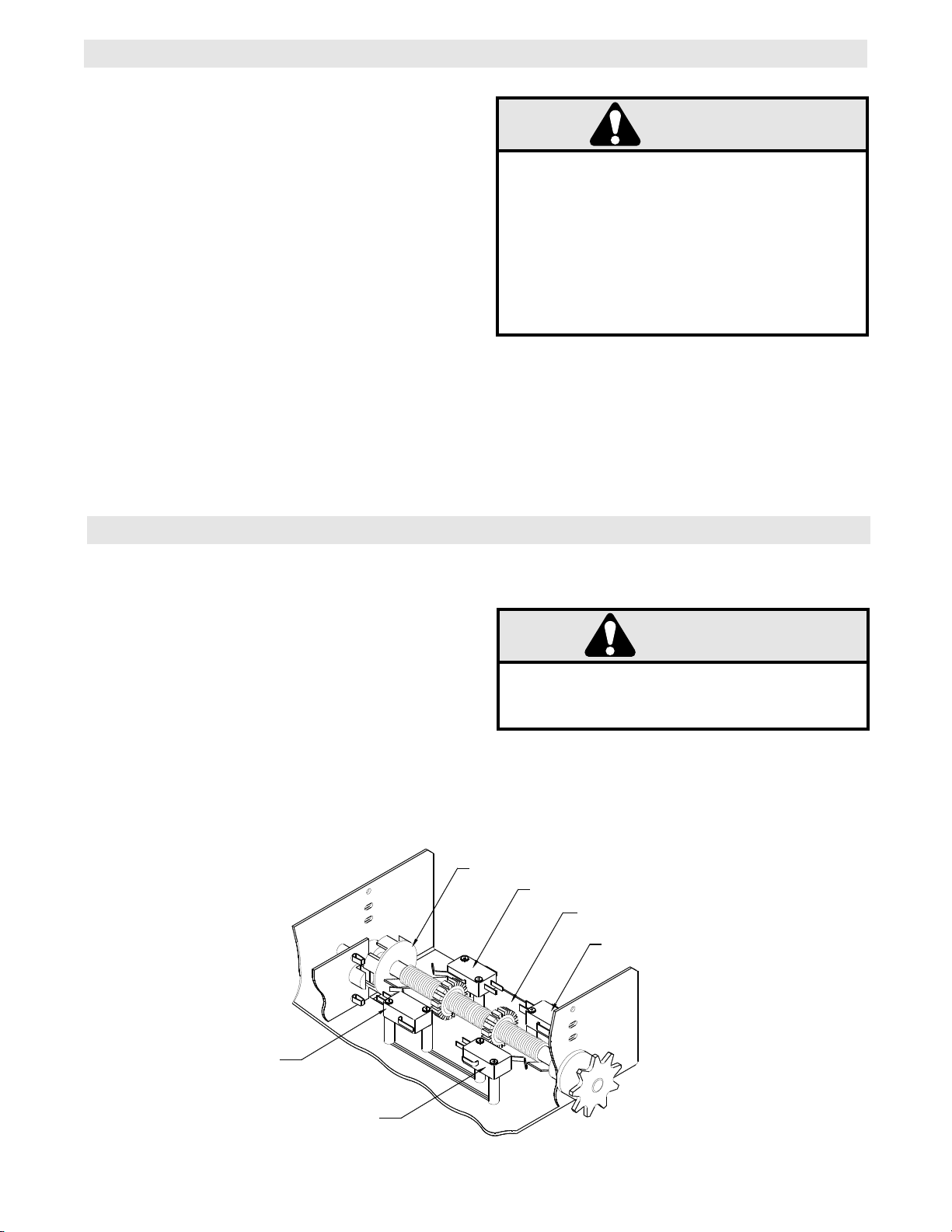
CLUTCH ADJUSTMENT
AUXILIARY REVERSE SYSTEM
WARNING
THIS OPERATOR CONTAINS AN AUXILIARY
REVERSE SYSTEM THAT REQUIRES PROPER
CLUTCH ADJUSTMENT IN ORDER TO
FUNCTION. AN IMPROPERLY ADJUSTED
CLUTCH MAY REDUCE THE LIFE OF THE
OPERATOR OR ITS COMPONENTS.
The Auxiliary Reverse System (A.R.S.) is NOT
intended and may not be used as an entrapment
protection device. A safety reversing edge or
infrared sensor should be added to door if
necessary.
1. Remove cotterpin from nut on the clutch shaft.
This operator has A.R.S., an auxiliary reverse system
to protect the door operator and its components. This
circuit recognizes change in speed of door in the
down direction caused by binding or obstructions.
Upon detection, the door will stop and return to fully
open position.
Friction Clutch Components
2. Back off clutch nut until there is very little tension
on the clutch spring.
3. Tighten clutch nut gradually until there is just
enough tension to permit the operator to move the
door smoothly but to allow the clutch to slip if the door
is obstructed. When the clutch is properly adjusted, it
should generally be possible to stop the door by hand
during travel.
4. Reinstall Cotterpin.
9
Page 10

EMERGENCY DISCONNECT SYSTEM
Header
Bracket
Straight
Door Arm
Assembly
Emergency
Release
Handle
Door
Bracket
Door
Chain
Clevis
Pin
Trolley
Emergency
Disconnect
Track
Pull emergency
release handle
straight down.
Emergency disconnect
will open.
Emergency
Disconnect
Curved
Door Arm
Door Arm
Lift free end of
door arm to trolley.
Pull emergency handle
to allow arm to engage
roll pin. Release handle.
Emergency disconnect
will close.
Emergency
Disconnect
Door Arm
N
O
TIC
E
TO DISCONNECT DOOR FROM OPENER
TO RECONNECT DOOR ARM TO TROLLEY
WARNING
WARNING
WARNING
DOOR ARM IS RELEASED FROM TROLLEY WHEN
EMERGENCY DISCONNECT OPENS.
TO AVOID BEING STRUCK BY DOOR ARM, DO NOT
STAND UNDER THE ROPE OR DOOR ARM WHEN
PULLING THE EMERGENCY RELEASE.
TEST THE SYSTEM
Turn on power. Test all controls and safety devices
to make sure they are working properly. It will be
necessary to refer back to page 6 for fine adjustment
of the limit switches.
IMPORTANT NOTES:
Do not leave operator power on unless all safety
and entrapment protection devices have been
tested and are working properly.
Be sure you have read and understand all Safety
Instructions included in this manual.
Be sure the owner or person(s) responsible for
operation of the door have read and understand
the Safety Instructions, know how to electrically
operate the door in a safe manner, and know how
to use the manual disconnect operation of the
door operating system.
WARNING
DO NOT PLACE HANDS OR TOOLS IN OR
NEAR THE OPERATOR WHEN THE POWER IS
ON OR WHEN TESTING CONTROL OR SAFETY
DEVICES. ALWAYS DISCONNECT POWER
BEFORE SERVICING OR ADJUSTING THE
OPERATOR.
10
Page 11

BRAKE ADJUSTMENT
A solenoid brake is an optional modification. If supplied, the brake is adjusted at the factory and should not need
additional adjustment for the the life of the friction pad.
Replace friction pads when necessary. Refer to the
Solenoid Brake System
illustration for identification of components for the
solenoid type brake system.
Solenoid
Release Lever
Friction Pads
Pulley
MAINTENANCE SCHEDULE
Check at the intervals listed in the following chart.
EVERY EVERY EVERY
ITEM PROCEDURE 3 MONTHS 6 MONTHS 12 MONTHS
Drive Chain Check for excessive slack.
Check & adjust as required.
Lubricate.*
Sprockets Check set screw tightness
●✔
●● ✔✔
Clutch Check & adjust as required
Belt Check condition & tension
Fasteners Check & tighten as required
Manual Disconnect Check & Operate
Bearings & Shafts Check for wear & lubricate
✳✳
Use SAE 30 Oil (Never use grease or silicone spray).
✔✔
Repeat ALL procedures.
■■
Do not lubricate motor. Motor bearings are rated for continuous operation.
■■
Do not lubricate clutch or V-belt.
■■
Inspect and service whenever a malfunction is observed or suspected.
■■
CAUTION: BEFORE SERVICING, ALWAYS DISCONNECT OPERATOR FROM POWER SUPPLY.
HOW TO ORDER REPAIR PARTS
OUR LARGE SERVICE ORGANIZATION
SPANS AMERICA
INSTALLATION AND SERVICE INFORMATION
ARE AVAILABLE 6 DAYS A WEEK
CALL OUR TOLL FREE NUMBER - 1-800-528-2806
HOURS 7:00 TO 3:30 p.m. (Mountain Std. Time)
MONDAY Through SATURDAY
●● ✔✔
WHEN ORDERING REPAIR PARTS
PLEASE SUPPLY THE FOLLOWING INFORMATION:
PART NUMBER DESCRIPTION MODEL NUMBER
ADDRESS ORDER TO:
THE CHAMBERLAIN GROUP, INC.
Electronic Parts & Service Dept.
2301 N. Forbes Blvd., Suite 104
●● ✔✔
●● ✔✔
●● ✔✔
●● ✔✔
Tucson, AZ 85745
11
Page 12

(OPTIONAL)
BIMETAL
CLOSE-A
RED AND YELLOW MOTOR WIRES.
* TO REVERSE MOTOR ROTATION INTERCHANGE
PULL SWITCH
OPEN & CLOSE
CLOSE
TO
SAFETY
EDGE
OPEN
BR
2
P
7
Y
10
GY
Y
AUX.
R1
BR
1
OR
GY
OPEN
AUX.
L/S
OPEN-B
BL
OR
12
BL
C
(OPTIONAL)
CLOSE L/S
BK
3
STOP
L2
BK
BK
4
R
OPEN-A
W
C
CAPACITOR
Y
N.O.
100W
MAX.
W
LIGHT
RELAY
C
SEC.
OPEN L.S.
CLOSE L/S
P
P
CL
OR
R
N.O.
R
OR
OP
N.C.
C
W
W
W
11
BR
L1
MOTOR *
R
Y
10VA.
PR1.
24VAC.
Y/BK
W
O/L
BK
A
B
W
WIRE NUT
R3
R2
34
215
GY
Y
R
W
RPM SENSOR BOARD
N.C.
C
MOVE JUMPER WIRE TO TERMINAL #2
FOR MOMENTARY CONTACT ON CLOSE
Y
WIRE NUT
CLOSE-B
RES.
BL
Y
SCHEMATIC DIAGRAM for MT5011
1753
12
Page 13

WIRING DIAGRAM for MT5011
S
C.
E
P
I.
R
Y/BK
W
CAPACITOR
OPEN
STOP
CLOSE
1234
PULL SWITCH TO
SAFETY EDGE
OPEN & CLOSE
1210711
120VAC
L2L1
OR P
Y
BR
BK
Y
BL
GYY
W BKBK
GROUND
OR
OP
P
CL
BL R
W
Y
BR
OR
BL
R
B
BK
R
Y
Y
NO
C
W
A
NC
NO
C
NC
BA
WIRE NUT
Y
O/L
MOTOR
BR
Y
R1
R3
R2
N.C.
N.O.
N.C.
GY
C
W
GY
P
OR
N.C.
N.C.
C
CLOSE
P
OR
C
W
OPEN
C
3
4
5
2
1
RADIO
REC'R
RPM
SENSOR
XFMR
AUX.CLOSE
AUX.OPEN
R
BR
ORP
INTERCHANGE RED & YELLOW WIRES.
TO REVERSE MOTOR DIRECTION
C2 WIRING - Constant Presssure to Close
RED WIRE ON TERMINAL #12 (Shipped from Factory)
B2 WIRING - Momentary Contact to Close
MOVE RED WIRE FROM TERMINAL #12 TO TERMINAL #2
*
CLOSE CONTROL WIRING OPTIONS
- Shipped from Factory
*
See Close Control
Wiring Options Below
RESISTOR
NUT
WIRE
Y
1753
13
Page 14

(OPTIONAL)
BIMETAL
CLOSE-A
RED AND YELLOW MOTOR WIRES.
* TO REVERSE MOTOR ROTATION INTERCHANGE
PULL SWITCH
OPEN & CLOSE
CLOSE
TO
SAFETY
EDGE
OPEN
BR
2
P
7
Y
10
GY
Y
AUX.
R1
BR
1
OR
GY
OPEN
AUX.
L/S
OPEN-B
BL
OR
12
BL
C
(OPTIONAL)
CLOSE L/S
BK
3
STOP
L2
BK
BK
CLOSE-B
4
R
OPEN-A
W
C
CAPACITOR
Y
N.O.
BL
100W
MAX.
W
LIGHT
RELAY
C
SEC.
OPEN L.S.
CLOSE L/S
P
P
CL
OR
R
N.O.
R
OR
OP
N.C.
C
W
W
W
11
BR
L1
MOTOR *
R
Y
10VA.
PR1.
24VAC.
Y
W
O/L
BK
A
B
W
WIRE NUT
R3
R2
34
215
GY
W
R
Y
A.R.S. BOARD
(When Present)
N.C.
C
MOVE JUMPER WIRE TO TERMINAL #2
FOR MOMENTARY CONTACT ON CLOSE
Y
HAND CHAIN
INTERLOCK SW.
(WHEN PRESENT)
BRAKE SOLENOID
CLOSE-C
OPEN-C
BL/BK
RES.
SCHEMATIC DIAGRAM for BMT5011
1754
14
Page 15

WIRING DIAGRAM for BMT
SECONDARY
PRIMARY
W
CAPACITOR
OPEN
STOP
CLOSE
1234
PULL SWITCH TO
SAFETY EDGE
OPEN & CLOSE
1210711
RATED LINE
VOLTAGE
L2L1
OR
P
Y
BR
BK
Y
BL
GYY
BK
BK
GROUND
OR
OP
P
CL
BL R
W
BL
BR
OR
BL
R
BK
R
Y
Y
W
WIRE NUT
Y
O/L
MOTOR
BR
R1
R3
R2
GY
W
CLOSE
P
OR
OPEN
3
4
5
2
1
RADIO
REC'R
XFMR
AUX.CLOSE
AUX.OPEN
R
BR
P
NO
C
NC
BA
NO
C
NC
C
NO
C
NC
BA
NO
C
NC
C
BRAKE
SOLENOID
N.O.
COM
INTLK.
Y
- INTERLOCK SWITCH (WHEN SUPPLIED)
WIRED N.O. HELD CLOSED.
**
**
INTERCHANGE RED & YELLOW WIRES.
TO REVERSE MOTOR DIRECTION
C2 WIRING - Constant Presssure to Close
RED WIRE ON TERMINAL #12 (Shipped from Factory)
B2 WIRING - Momentary Contact to Close
MOVE RED WIRE FROM TERMINAL #12 TO TERMINAL #2
*
CLOSE CONTROL WIRING OPTIONS
- Shipped from Factory
*
See Close Control
Wiring Options Below
W
BL/BK
BL/BK
BL/BK
A.R.S. BOARD
(When Present)
Y
W
N.C.
COM
COM
N.C.
N.O.
GY
N.C.
OR
W
COM
P
R
Y
R
RESISTOR
Y
GY
1754
15
Page 16

ELECTRICAL BOX - ILLUSTRATED PARTS
2
L2
S5
S3
S4
S5
S3
S4
S8
S2
S1
S6
L6
L4
L5
L8
L3
L1
L7
L8
L6
10
L2
7
8
5
4
L3
S7
9
3
6
1
11
16
Page 17

REPLACEMENT PART KITS
Below are replacement kits available for your operator. For replacement of electrical box, motor or brake components be sure to match model number of your unit to kit number below to ensure proper voltage requirements.
Optional modifications and/or accessories included with your operator may add or remove certain components
from these lists. Please consult a parts and service representative regarding availability of individual components
of kits specified below. Refer to page 11 for all repair part ordering information.
Complete Electrical Box
K-MT5011 Model MT5011, 115V Single Phase
K-MT5025 Model MT5025, 230V 50Hz
K-BMT5011 Model BMT5011, 115V Single Phase
K-BMT5025 Model BMT5025, 230V 50Hz
Electrical Box Sub-Assemblies
K72-12487 Limit Shaft Assembly
K75-12493 Limit Switch Assembly
K75-12489 Auto Reversal System(ARS) PCB
Motor Kits
K20-5150LD Models MT5011, BMT5011
K20-5250LD Models MT5025, BMT5025
Shaft Assemblies
K72-12471 Clutch Shaft Assembly
K72-12472 Output Shaft Assembly
Hardware, Track, and Drive Chain Kits
K75-12491 Hardware Kit
See pg. 19 Drive Chain
See pg. 19 Track
Brake Kits
K75-12492 Model BMT5011 Brake Assembly
K75-12494 Model BMT5025 Brake Assembly
VARIABLE COMPONENT KITS
Part Number
13-10024
23-10041
29-2
21-10340
21-5230
29-10338
29-12110
24-24-1
24-24-6
Component
Limit Nut
Limit Switch
Resistor, 20hm
Transformer, 115V
Transformer, 230V
Capacitor, 70MFD
Capacitor, 20MFD
Relay, DPDT
Relay, 3PDT
MT5011
MT5025
BMT5011
BMT5025
QTY
1
2
4
8
8
2
4
2
QTY
1
2
2
1
1
7
1
2
K72-12487 LIMIT SHAFT ASSEMBLY KIT
ITEM
L1
L2
L3
L4
L5
L6
L7
L8
DESCRIPTION
MT Limit Shaft
Flange Bearing 3/8” I.D.
Limit Nut
Sprocket 48B9 x 3/8” Powder Metal
RPM Sensor Rotating Cup
Washer, Shim 3/8” I.D. x .010 THK.
Rollpin 1/8 x 1” Long
E Ring, 3/8”
K75-12493 LIMIT SWITCH ASSEMBLY KIT
PAR T #
11-10321
12-10028
13-10024
15-48B9A1
29-10344B
80-10026
86-RP04-100
87-E-038
ITEM
S1
S2
S3
S4
S5
S6
S7
S8
DESCRIPTION
Depress Plate
Spring, Depress Plate
Limit Switch
Standoff, Limit Switch
Screw, #4-40 x 1-3/8” Pan Hd Phil
Screw, #6-32 x 1” Pan Hd Phil
Nut, Double Tinnerman
Locknut, #6-32 Nylon Hex
PAR T #
10-10318
18-10036
23-10041
31-10043
82-PX04-19
82-PX06-16
84-DT-04
84-LN-06
ITEM
1
2
3
4
5
6
7
8
9
10
11
PART #
10-10315
10-10316
23-10916
29-2
42-10040
42-110
001A5834
74-10352
(See Var. Comp.)
(See Var. Comp.)
(See Var. Comp.)
DESCRIPTION
MT Electrical Box
MT Electrical Box Cover
SPDT Interlock Switch (Not on MT)
Resistor, 2ohm
Terminal Assembly 3 Lug
10 Position Terminal Block
RPM Sensor Board (MT Only)
RPM Sensor Board Harness
Transformer
Relay, 24V
Motor Capacitor
QTY
1
1
1
1
1
1
1
1
1
2
1
INDIVIDUAL PARTS
17
Page 18

ILLUSTRATED PARTS
H5
H4
H6
H8
H3
O6
O9
O4
09
O10
C16
O8
09
C10
O2
C14
O3
C15
O1
C3
C2
CH
Brake Components - Model BMT Only
B17
B7
B4
B2
B14
B18
B11
B19
TR
H7
H2
H1
O2
O8
O5
MTR
B1
B15
B13
B3
B6
B9
Brake Components - Model BMT Only
B16
B12
B8
B5
EB
B10
C3
18
C9
O7
C4
C10
C6
C7
C11
C1
C13
C8
C5
C12
Page 19

REPLACEMENT PARTS LISTS
Refer to the parts lists below for replacement kits available for your operator. If optional modifications and/or accessories
are included with your operator, certain components may be added or remove from these lists. Individual components of
each kit may not be available. Please consult a parts and service representive regarding availability of individual
components. Refer to page 11 for all repair part ordering information.
BRAKE ASSEMBLY KITS
KIT PART #
K75-12492
K75-12494
Brake kits for models BMT only
ITEM PART # DESCRIPTION QTY
10-10354
B1
10-10355
B2
10-10356
B3
10-10357
B4
17-10363
B5
18-10362
B6
22-120
B7
22-240
31-10364
B8
75-10359
B9
82-NH25-03
B10
82-PX10-06T
B11
82-PX10-28
B12
82-SH06-065
B13
83-HS08-04
B14
84-LH-06
B15
84-LH-10
B16
85-FW-10
B17
85-LS-10
B18
86-CP05-108
B19
FOR OPERATOR(S)
Model BMT5011
Model BMT5025
Brake Release Arm
Solenoid Link
Brake Mounting Plate
Solenoid Bracket
Pully & Disc Assembly
Comp. Spring .360 O.D. x .045WD
115V Brake Solenoid
230V Brake Solenoid
Spacer .20 I.D. x .260 OD x 1
Brake Plate Pad Assembly
1/4-20 x 3/16 S.S. Knurled Cup
Phillips Pan Self Tap Type ZP
10-32 x 3” SLTD PN HD ZP
SH Cap Screw #6-32 W/Knrld Cup
Sheet Metal Screw AB Hex Slot
Locknut #6-32
Nylon Locknut 10-32 ZP
Flatwasher #10 ZP
Lock Washer ZP
Cotterpin 5/32” x 1-1/2” Long
K77-12486 HARDWARE KIT
ITEM PART # DESCRIPTION QTY
H1
H2
H3
H4
H5
H6
H7
H8
10-10203
10-10204
10-10205
11-10130
75-10170
75-10174
75-10214
75-10259
Curved Arm
Door Bracket
Header Bracket
Header Pivot Pin
Slider Assembly
Front Idler Assembly
Straight Arm Assembly
Track Spacer Assembly
K75-12870 STRAIGHT & CURVED ARM ASSY
H1
H7
10-10203
75-10214
Curved Arm
Straight Arm Assembly
MOTOR
See Page 17 For More Information
K72-12471 CLUTCH SHAFT ASSEMBLY KIT
ITEM PART # DESCRIPTION QTY
C1
10-10166
C2
11-10320
C3
12-10029
C4
2
1
1
1
1
4
1
1
2
1
1
4
1
4
4
2
1
4
4
1
ITEM PART # DESCRIPTION QTY
1
1
15-48B10GXX
C5
16-4L290
C6
17-10336
C7
18-10164
C8
39-10167
C9
80-10022
C10
80-10023
C11
84-SH-76
C12
85-FW-75
C13
86-CP04-112
C14
86-RP08-102
C15
86-RP08-200
C16
87-P-025
K72-12472 OUTPUT SHAFT ASSEMBLY KIT
O1
11-10319
O2
12-10029
O3
15-48B10GXX
O4
15-48B10G1
O5
15-48B24GXX
O6
19-48027M
O7
19-48033M
O8
80-10023
O9
86-RP08-102
O10
87-P-025
Clutch Plate
Clutch Shaft
Bearing 3/4” I.D.
Sprocket, 48B10 x 3/4”
Cogged Belt
4L Motor Pulley 7” O.D.
Spring, Clutch (1/3 & 1/2 HP)
Clutch Disc
Shim Washer Thick
Shim Washer Thin
Nut 3/4-16 Castle
Flatwasher 3/4” I.D.
Cotterpin 1/8” x 1-3/4” Long
Roll Pin 1/4” x 1-1/8” Long
Roll Pin 1/4” x 2” Long
Turac 3/4” Push on Fastener
Output Shaft
Bearing 3/4” I.D.
Sprocket, 48B10 x 3/4”
Sprocket, 48B10 x 3/4” Powder Metal
Sprocket, 48B24 x 3/4”
Chain #48 x 27 Links with master link
Chain #48 x 33 Links with master link
Shim Washer Thin
Roll Pin 1/4” x 1-1/8” Long
Turac 3/4” Push on Fastener
1
1
2
1
1
1
1
1
2
4
1
5
1
1
1
2
1
2
1
1
1
1
1
2
3
2
1
1
1
1
1
ITEM PART # DESCRIPTION
TR
2
CH
DOOR TRACK & DRIVE CHAIN
10-5810 Track for up to 10’ door height
10-5812 Track for 12’ door height
19-5810 #48 Chain for up to 10’ door height
19-5812 #48 Chain for 12’ door height
1
1
ELECTRICAL BOX REPLACEMENT KITS
ITEM DESCRIPTION KIT #
EB
Electrical Box Replacement Kits
See Page 17
19
Page 20

CONTROL CONNECTION DIAGRAM
c
2003, The Chamberlain Group, Inc.
All rights Reserved
01-10332L
IMPORTANT NOTES:
1) The 3-Button Control Station provided must be connected for operation.
2) If a STOP button is not used, a jumper must be placed between termianls 3 and 4.
3) Auxiliary control equipment may be any normally open two wire device such as
pullswitch, single button, loop detector, card key or such device.
3 BUTTON STATION or 3 POSITION KEYSWITCH w/ SPRING RETURN TO CENTER AND STOP BUTTON
STANDARD
1 2 3 4
Open
Close
Stop
2 BUTTON STATION or 3 POSITION KEYSWITCH w/ SPRING RETURN TO CENTER
2 OR MORE KEY LOCKOUT
1 2 3 4
Open
Close
Stop
Open
Close
Stop
ATTENTION ELECTRICIAN:
USE 16 GAUGE OR HEAVIER WIRE
FOR ALL CONTROL CIRCUIT WIRING.
1 2 3 4
Open
Close
Stop
Keyswitch
STANDARD
1 2 4
SEE NOTE #2
Open
Close
1 BUTTON STATION or ANY AUXILIARY DEVICE
3
7
To Open, Close, and Reverse while closing
SENSING DEVICE TO REVERSE OR STOP
2 OR MORE
1 2 4
SEE NOTE #2
Open
Close
RESIDENTIAL RADIO CONTROLS
OPEN TIMER TO CLOSE
R1
RADIO CONTROL
EXTERNAL INTERLOCK
R2
Open
Close
R3
TERMINAL BLOCK
EXTERNAL
3
10
Sensing Device
3
STOP
4
EXT.
INTERLOCK
 Loading...