

Page 1

V 0503
Page 2

UL Listings and Instructions 2-5
Role of Specifiers and Designers 6
Role of Dealers, Installers and Trained Gate System Technicians 6
Role of End Users / Home Owners 7
Swing Gate Systems 7
Warnings and Precautions 8
“Open to the Inside” Mounting Specifications 9
“Open to the Outside” Mounting Specifications 10
Step-by-Step Operator Mounting Instructions 11-14
Removing the Control/Surge Suppressor Boards 15
Mounting the Control Box 15
Wiring 1 Operator to the Surge Suppressor Board 16
Wiring 2 Operators (Master/Slave) to the Surge Suppressor Board 17
Choosing Gate Movement Direction 18
Sensor Adjustment 18
Adjustable Timer 19
Earth Ground Rod Installation 19
Connecting Power Supply 20
Wiring Additional Inputs 21
Single Operator Loop Size and Placement 22
Master / Slave Loop Size and Placement 23
Loop Installation and Number of Wire Turns 24
Loop Detector Wiring 25
Photocell Installation 26
Single Control Board Description 27
Master / Slave Control Board Description 28
Surge Suppressor Board Description 29
Alarm / Maglock Control Board Connections 30
UL Audio Alarm 31
Burglar Alarm and Proximity Switch 31
“Gate Opening Inside” Installation of Maglock / Solenoid Relay 32
“Gate Opening Outside” Installation of Maglock / Solenoid Relay 33
Close Delay Option (Master / Slave Only) 34-35
Emergency Key Release 36
Troubleshooting 37-39
Optional Solar Power 40
Miracle 1 Accessories 41
Miracle 1 Parts Illustration 42
Miracle 1 Parts List / Maintenance 43
Features and Specifications 45
Quick Reference Surge Suppressor Wiring Diagram 46-47
Please DO NOT
Touch me!...
Unless you are an
Authorized Service
Technician!
TABLE OF CONTENTSTABLE OF CONTENTST A B L E O F C O N T E N T S
© 1998-2003 BY ELITE ACCESS SYSTEMS, INC.
Release 3
04/03
All rights reserved. No part of this manual may be
reproduced in any means without the expressed written
permission of the publisher. Materials, components and
specifications are subject to change without notice.
Attention:
This handbook is exclusively for qualified installation personnel, and assistance and/or maintenance
service. - The performances indicated in this handbook are valid only if a correct assembly has been carried out.
For Toll Free Technical Support: 1-888-ELITE-10
1
Page 3

UL LISTINGS AND INSTRUCTIONSUL LISTINGS AND INSTRUCTIONSU L L I S T I N G S A N D I N S T R U C T I O N S
Install the gate operator only when:
The operator is appropriate for the construction and the usage Class of the gate.
All exposed pinch points are eliminated or guarded, and
Guarding is supplied for exposed rollers.
The operator is intended for installation only on gates used for vehicles. Pedestrians must be
supplied with a separate access opening.
The gate must be installed in a location so that enough clearance is supplied between the gate
and adjacent structures when opening and closing to reduce the risk of entrapment. Swinging
gates shall not open into public access areas.
The gate must be properly installed and work freely in both directions prior to the installation of
the gate operator.
Controls must be far enough from the gate so that the user is prevented from coming in contact
with the gate while operating the controls. Controls intended to be used to reset an operator after
2 sequential activations of the entrapment protection device or devices must be located in the line
of sight of the gate outdoor. Easily accessible controls shall have a security feature to prevent
unauthorized use.
All warning signs and placards must be installed where visible in the area of the gate. A minimum
of two placards shall be installed. A placard is to be installed in the area of each side of the gate
and be visible to person located on the side of the gate on which the placard is installed.
A)
B)
C)
D)
E)
F)
Installation Instructions Regarding the Gate Operator
1.
2.
3.
2
Page 4

UL LISTINGS AND INSTRUCTIONSUL LISTINGS AND INSTRUCTIONSU L L I S T I N G S A N D I N S T R U C T I O N S
For a gate operator utilizing a non-contact sensor such as a photo beam:
See instructions on the placement of non-contact sensor for each type of application.
Care shall be exercised to reduce the risk of nuisance tripping, such as when a vehicle
trips the sensor while the gate is still moving.
One or more non-contact sensors shall be located where the risk of entrapment or
obstruction exists, such as the perimeter reachable by a moving gate or barrier.
A hard wired contact sensor shall be located and its wiring arranged so that the
communication between the sensor and the gate operator is not subjected to mechanical
damage.
A wireless contact sensor such as the one that transmits radio frequency (RF) signals to
the gate operator for entrapment protection functions shall be located where the
transmission of the signals are not obstructed or impeded by building structures, natural
landscaping or similar obstruction. A wireless contact sensor shall function under the
intended end-use conditions.
One or more contact sensors shall be located on the inside and outside leading edge of a
swing gate. Additionally, if the bottom edge of a swing gate is greater than 6 inches (152
mm) above the ground at any point in its arc of travel, one or more contact sensors shall
be located on the bottom edge.
For a gate operator utilizing a contact sensor such as an edge sensor:
G)
H)
1.
2.
3.
1.
2.
3.
3
Page 5

UL LISTINGS AND INSTRUCTIONSUL LISTINGS AND INSTRUCTIONSU L L I S T I N G S A N D I N S T R U C T I O N S
READ AND FOLLOW ALL INSTRUCTIONS.
Never let children operate or play with gate controls. Keep the remote control away from
children.
Always keep people and objects away from the gate.
NO ONE SHOULD CROSS THE PATH OF A MOVING GATE!
Test the gate operator monthly. The gate MUST reverse on contact with a rigid object or
stop when an object activates the non-contact sensors. After adjusting the force or the
limit of travel, retest the gate operator. Failure to adjust and retest the gate operator
properly can increase the risk of injury or death.
Use the emergency release only when the gate is not moving. Make sure the power for
the gate operator is off.
KEEP GATES PROPERLY MAINTAINED. Read the manual. Have a qualified service
person make repairs to the gate or gate hardware.
The entrance is for vehicles only. Pedestrians must use separate entrance.
SAVE THESE INSTRUCTIONS.
1.
2.
3.
4.
5.
6.
7.
8.
Important Safety Instructions
Warning -
To reduce the risk of injury or death:
4
Page 6
UL LISTINGS AND INSTRUCTIONSUL LISTINGS AND INSTRUCTIONSU L L I S T I N G S A N D I N S T R U C T I O N S
Gate – A moving barrier such as a swinging, sliding, raising lowering, rolling, or like, barrier,
that is a stand-alone passage barrier or is that portion of a wall or fence system that controls
entrance and/or egress by persons or vehicles and completes the perimeter of a defined
area.
Vehicular horizontal slide-gate operator (or system) – A vehicular gate operator (or
system) that controls a gate which slides in a horizontal direction that is intended for use for
vehicular entrance or exit to a drive, parking lot, or the like.
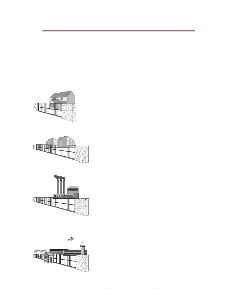
Residential vehicular gate operator – Class I – A vehicular gate
operator (or system) intended for use in a home of one-to four
single family dwelling, or a garage or parking area associated
therewith.
Commercial/General access vehicular gate operator –
Class II – A vehicular gate operator (or system) intended for
use in a commercial location or building such as a multifamily housing unit (five or more single family units) hotel,
garages, retail store or other building servicing the general
public.
Commercial/General access vehicular gate operator –
Class III – A vehicular gate operator (or system) intended for
use in an industrial location or building such as a factory or
loading dock area or other locations not intended to service
the general public.
Restricted access vehicular gate operator – Class IV – A
vehicular gate operator (or system) intended for use in a
guarded industrial location or building such as an airport
security area or other restricted access locations not
servicing the general public, in which unauthorized access is
prevented via supervision by security personnel.
5
Page 7

6
Specifiers and designers should design an automatic vehicular gate system to:
• Incorporate UL 325 compliant equipment.
• Utilize an operator suited for gate system type, size, frequency of use, location and user population
(Refer to UL 325 for usage class definitions)
• Separate pedestrian access from vehicle access.
• Reduce or eliminate pinch points.
• Reduce risk of entrapment injuries by minimizing all gaps in the gate and enclosing the area of the
travel of the gate.
• Secure controls from unauthorized use.
• Locate all controls out of reach from the gate.
• Allow the user full view of the gate when operating.
• Consider special populations, such as children or the elderly.
• Conspicuously display all warnings and instructions.
• Be consistent with DASMA’s Automatic Gate Opener System Safety Guide.
ROLE OF SPECIFIERS AND DESIGNERS
Installers, during the course of the installation proceedings for each job, should:
• Confirm that the gate operator being installed is appropriate for the application.
• Confirm that the gate is designed and built according to current published industry standards.
• Confirm that all appropriate features and accessory devices are being incorporated, including both
primary and secondary entrapment protection devices.
• Make sure that the gate works freely before installing the operator.
• Repair or service worn or damaged gate hardware before installing the operator.
• Eliminate all gaps in the sliding gate below a 4 foot height that permit a 2 1/4 inch sphere to pass
through any location, including the area of the adjacent fence covered when the gate is in the open
position.
• Install the gate operator according to the manufacturer’s installation instructions.
• Adjust the operator clutch or load-sensing device to the minimum force setting that allows reliable gate
operation.
• Install operator inside fence line (DO NOT install operator on public side of fence line)
• Install a proper electrical ground to a gate operator.
• Install keypad controls where users cannot touch, or reach through gate while operating controls.
• Install controls where user has full view of gate operation.
• Install all warning signs (In accordance with UL 325) on both sides of the gate to warn persons in the
area of potential hazards associated with automatic vehicular gate operation.
•Test all features for proper functions before placing the automatic vehicular gate into service.
• Demonstrate the basic functions and safety features of the gate system to owners/end users/general
contractors, including how to turn off power and how to operate the manual disconnect feature.
• Leave safety instructions, product literature, installation manual and maintenance manual with end
user.
• Explain to the owners the importance of a service contract that includes a routine re-testing of the
entire system including the entrapment protection devices, and explain the need for the owners to
insure that this testing is performed routinely.
• Offer the owner/end user a maintenance contract, or contact them regularly to offer maintenance.
ROLE OF DEALERS, INSTALLERS AND
TRAINED GATE SYSTEM TECHNICIANS
Page 8

7
End users should be made aware that they must:
• Contact a trained gate systems technician to maintain and repair the gate system (End users should
never attempt to repair the gate)
• Retain and utilize the installation and maintenance manual and safety instructions.
• Routinely check all gate operator functions and gate movement.
• Discontinue use if safety systems operate improperly, the gate is damaged, or the gate is difficult to
move.
• Never overtighten the operator clutch of load sensing device to compensate for a damaged or stiff
operating gate.
• Prominently display and maintain warning signs on both sides of the gate.
• Keep all obstructions clear of the vicinity of the path of the gate system.
• Actively discourage pedestrian use of the vehicular gate operating system.
• Prevent anyone from playing near any part of the gate system.
• Never allow anyone to climb under, over or through a gate or the adjacent fence area.
• Never allow children to operate gate.
• Keep portable controls out of reach of children.
• Never allow anyone to install an operating control within reach of the gate.
• Never allow anyone to install a horizontal slide gate with exposed rollers or openings large enough to
allow a sphere of 2 1/4 inches to pass through any portion of the gate below a 4 foot height, including
the area of the adjacent fence covered when the gate is in the open position.
• Always be certain that the gate area is clear of pedestrians before operating the gate.
ROLE OF END USERS/HOME OWNER
• Entrapment Zone Hazard - Body parts may become entrapped between a gate and a stationary object
when the gate begins to move, which can result in serious injury or death. Pedestrians must stay clear
of the gate path, and any area where gate motion is close to stationary objects.
• Pinch Points Hazard - The opening mechanism may have arms that can overlap with a scissoring
effect, which can result in serious injury. Pedestrians must stay clear of the opening mechanism at all
times, particularly when gate is opening.
Be sure that warning signs are prominently displayed on both sides of the gate and any other place
where danger exists.
SWING GATE SYSTEMS
Page 9
WARNINGS AND PRECAUTIONSWARNINGS AND PRECAUTIONSW A R N I N G S A N D P R E C A U T I O N S
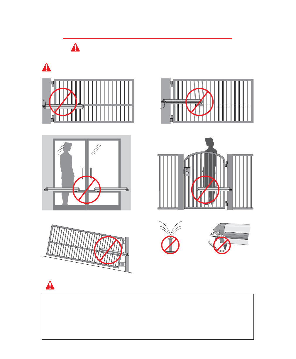
Warning - To reduce the risk of injury to persons,
The Miracle-1 is for Vehicular Gate use ONLY!
DO NOT install on ANY pedestrian gates.DO NOT install on ANY pedestrian passageways or
doorways.
DO NOT install upside down.
DO NOT install next to
sprinklers or any area that
may expose bottom of
operator to water.
Caution - If the “Timer” is to be left in the “ON” position, then add a safety loop and center loop.
DO NOT install on a few pickets, they will bend.
Weld a reinforcement bar across entire gate.
DO NOT over-bend the
cord from the operator.
Doing this will cause the
wires to eventually break.
DO NOT install on uphill or downhill gates.
Be sure to read and follow all these important instructions before installation of the gate operator. Elite
Access Systems, Inc. is not responsible for improper installation or failure to comply with local building and
electrical codes.
IMPORTANT SAFETY INSTRUCTIONS
WARNING - To reduce the risk of severe injury or death:
1. READ AND FOLLOW ALL INSTRUCTIONS.
2. Never let children operate or play with gate controls. Keep the remote control away from children.
3. Always keep the moving gate in sight and away from people and objects until it is completely closed.
NO ONE SHOULD CROSS THE PATH OF THE MOVING GATE.
4. KEEP GATES PROPERLY MAINTAINED. Read the owner’s manual. Have a qualified service person periodically inspect and
make repairs to gate hardware.
5.
SAVE THESE INSTRUCTIONS.
8
Page 10

10.25"
90° / 105°
8.5"
6"
7.75"
25.75"
Miracle
1
i
n
Closed
Posit
ion
Miracle
1
i
n
Op
e
n
Positio
n
Gate in Closed Position
Gate in Open Position
Out
In
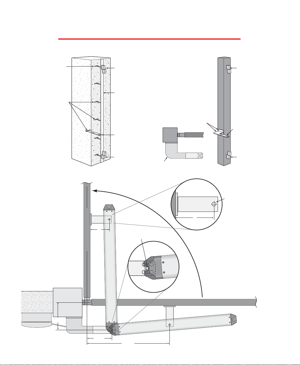
PROCEDURE FOR INSTALLATION
Typical Masonry Column Setup
Typical Steel
Post Setup
Important:
Weld Re-Bar
Behind Gate
Hinges for
Maximum
Strength
Heavy Steel
Plates for
Reinforcement
(Not Supplied)
Heavy Steel Plates for
Reinforcement
(Not Supplied)
Gate Hinge
Gate Hinge
Steel Re-Bar
10"
Minimum
Back Steel Bracket
(Reinforce if necessary)
Back Steel Bracket
(Reinforce if
necessary)
Gate Hinge
Gate Hinge
Indexing on central hole in
the back steel bracket.
Indexing on
mounting hole in
the front steel
bracket.
6"
Top View
Post Setup
Heavy
Steel
Plate
Open To The Inside
9
Page 11
Gate in Open Position
Gate in Closed Position
90° / 105°
7.75"
8.5"
25.75"
Out
In
PROCEDURE FOR INSTALLATION
Typical Masonry
Column Setup
Typical Steel
Post Setup
Top View
Post Setup
Indexing on central hole in
the back steel bracket.
Indexing on
mounting hole in
the front steel
bracket.
This Plate
Not Supplied
Back Steel
Bracket
(Reinforce
if necessary)
Back Steel Bracket
(Reinforce if necessary)
Heavy Steel Plates
for Reinforcement
(Not Supplied)
Heavy Steel
Plate
Gate Hinge
Gate HingeGate Hinge
6"
6"
Miracle 1 in Open Position
Miracle
1
i
n
Closed
Posit
io
n
Important:
Weld Re-Bar
Behind Gate
Hinges for
Maximum
Strength
Steel Re-Bar
Gate Hinge
Heavy Steel Plate for
Reinforcement
(Not Supplied)
Open To The Outside
10
Page 12
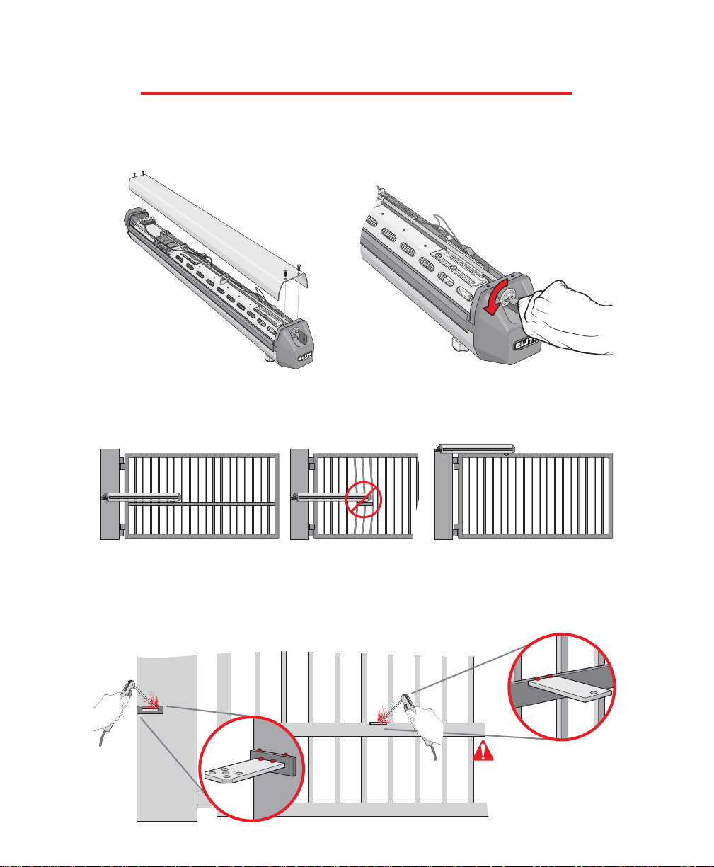
PROCEDURE FOR INSTALLATION
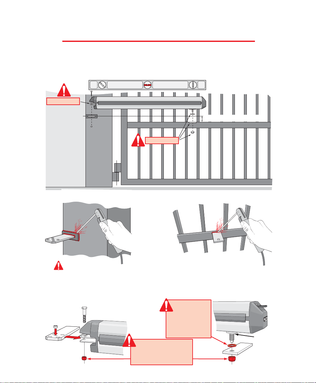
Step 3: Position the Miracle 1 horizontally level on the closed gate, where desired. For strength purposes, the
front steel bracket must be attached in an area that can withstand heavy forces. Additional reinforcement steel
plates may be necessary for mounting.
Step 4: Position and level the operator brackets and reinforcement plates. (See next page). Tack weld brackets
and plates in position.
Step 1: Remove the 4 screws and lift the
operator cover off.
Step 2: Release the mechanical lock by turning the
key to the horizontal position.
If using a gate crossbar, weld bar across all pickets. Do not weld
the crossbar on a few pickets, or they will bend.
The Miracle 1 can be mounted on top
of the gate frame.
Important:
Tack weld the front steel
bracket at the top of the
crossbar, so the operator
will not hit the crossbar
when in motion.
Mounting Instructions
11
Page 13
PROCEDURE FOR INSTALLATION
2.25" Vertical Height Difference
Step 4 (con't): The gate must be in the closed position. Make sure the operator is kept level while tack
welding the front and back steel brackets and reinforcement steel plates in position. After all tack welding is
finished, remove the operator!
Caution: Welding the brackets with the operator attached to the gate may damage the operator.
Step 5: With the operator removed, completely weld around the brackets and plates on the gate.
Step 6: Remove the nut, bolt and bushing from
the back operator bracket. Place the metal bushing
in the hole of the steel bracket that will be used.
Secure operator with the nut and bolt (See Below).
Step 7: Remove the nut from the traveler carriage at
the front of the operator. Secure operator to the front
bracket with the washer and nut (See Below).
Metal
Bushing
Tra veler
Carriage
Front Bracket
Back
Bracket
Mounting Instructions
Refer to Step 7
Refer to Step 6
Important:
Washer Must be
placed between
traveler carriage
and TOP of front
bracket.
Important:
These nuts MUST be tight
or unit will not work
correctly!
12
Page 14

Click!
PROCEDURE FOR INSTALLATION
Step 9: Lock the operator by turning the
key to the vertical position while pushing
or pulling on the gate until you hear the
key release click into place. The gate
should not move after the operator has
been locked. Completing this successfully
finishes the basic mounting of the
operator to the gate. The next steps are to
make all electrical connections to the
operator and control board.
Step 10: The following pages show the correct electrical procedures needed for the operator. After completing
all the electrical connections, continue to step 11 to complete the final adjustments on the operator.
Mounting Instructions
Step 8: Make sure that the operator is level or it will not function properly. An off-level installation may
cause the gate or operator to fail prematurely.
Push or Pull
13
Page 15

Step 11: Adjust the travel distance of the gate with the limit switches. Loosen the 2 screws of each limit switch
armature. Slide to adjust. Position the outside limit switches of each armature to stop the gate in the “full open”
and “full closed” positions. Re-tighten armature screws when gate positions are correct.
Step 12: Reinstall the operator cover with the 4 screws to complete
the installation.
Outside Limit
Switch
Outside Limit Switch
Inside Limit
Switch
Inside Limit Switch
Limit Switch
Armature
Limit Switch Armature
Adjustment Screws
Adjustment Screws
PROCEDURE FOR INSTALLATION
Adjusting the Limit Switches
14
Page 16

REMOVING THE CONTROL / SURGE BOARDS
MOUNTING THE CONTROL BOX
Remove the four nuts and remove battery rack.
Reverse this process to reinstall.
Mount control box with four screws and washers
(recommend #10 thru 1/4-20 Bolts or Screws)
Do Not over tighten.
Caution: Do Not make new mounting holes, or enlarge existing holes in control box.
Use the four mounting holes provided.
BLACK
MOTOR
WHITE
RED
BRAKE
SINGLE OR MASTER ONLY SLAVE ONLY
BROWN
BLUE
LIMITS
GREEN
BLACK
MOTOR
WHITE
RED
BRAKE
BROWN
BLUE
LIMITS
GREEN
CENTER
LOOP
+24 VAC
INPUT
SAFETY
LOOP
EXIT
LOOP
BURGLAR
ALARM
INPUT
GROUND
RADIO
+24 VOLT
UL SENSOR
LAKE FOREST, CALIFORNIA
www.eliteaccess.com
REV A
MIRACLE SURGE PROTECTION
123456 789101112 13141516 17181920212223 24252627
®
8
BLACK
MOTOR
WHITE
RED
BRAKE
SINGLE OR MASTER ONLY SLAVE ONLY
BROWN
BLUE
LIMITS
GREEN
BLACK
MOTOR
WHITE
RED
BRAKE
BROWN
BLUE
LIMITS
GREEN
CENTER
LOOP
+24 VAC
INPUT
SAFETY
LOOP
EXIT
LOOP
BURGLAR
ALARM
INPUT
GROUND
RADIO
+24 VOLT
UL SENSOR
LAKE FOREST, CALIFORNIA
www.eliteaccess.com
REV A
MIRACLE SURGE PROTECTION
123456 789101112 13141516 1718192021222324252627
®
Unscrew the 4 Phillips head screws from the cover.
Unplug the J1 and J3 plugs.
Unplug battery connector.
Unplug all accessory wires from Surge Suppressor's removable
terminals.
Disconnect ground wire.
Remove three Phillips screws from control board and remove board.
Remove three Phillips screws from surge suppressor board and
remove board.
PO
WE
R
C
HARG
E
O
K
BA
TT
ER
Y
L
O
W
®
A
CCESS SYSTE
MS INC
AC
C
E
SS
SYST
E
M
S
I
N
C
MA
G
L
O
CK
R
E
P
LAC
E
F
U
S
E
WHE
N
L
E
D
I
S
O
N
R
E
V
E
R
S
E
S
E
NS
OR
SYS
TEM
ON
ALA
RM
ALA
RM
S
E
NS
OR
O
P
E
N
I
NS
I
DE
OFF
N
O
Y
E
S
ON
T
I
ME
R
C
E
N
TR
AL
S
TR
IK
E
O
P
E
N
S
A
F
E
T
Y
L
OO
P
R
A
D
IO
R
E
C
C
E
N
T
E
R
L
OO
P
C
O
N
TRO
L
6
0
3
S
TO
P
B
Y
PO
SI
T
I
V
E
STO
P
O
PE
N
OUTSIDE
1
1
1
1
2
2
2
3
3
5
5
4
4
6
6
7
7
4
15
Page 17

BLACK
MOTOR
WHITE
RED
BRAKE
SINGLE OR MASTER ONLY SLAVE ONLY
BROWN
BLUE
LIMITS
GREEN
BLACK
MOTOR
WHITE
RED
BRAKE
BROWN
BLUE
LIMITS
GREEN
CENTER
LOOP
+24 VAC
INPUT
SAFETY
LOOP
EXIT
LOOP
BURGLAR
ALARM
INPUT
GROUND
RADIO
+24 VOLT
UL SENSOR
LAKE FOREST, CALIFORNIA
www.eliteaccess.com
REV A
MIRACLE SURGE PROTECTION
1 23456 789101112 13141516 171819202122232425262
®
WIRING 1 OPERATOR TO BOARD
Install the Flex Connector (supplied)
to secure the wire in the Miracle 1
Control Board Box.
Install a dedicated water tight
conduit for 6 wires. DO NOT run AC
wire in same conduit as 6 wires!
More than 20 ft run, use shielded
wire for the blue and green lines.
Shield must be grounded.
Water tight conduit
and flex connector
secured to control
box.
8
Important:
BLACK
MOTOR
WHITE
RED
BRAKE
SINGLE OR MASTER ONLY SLAVE ONLY
BROWN
BLUE
LIMITS
GREEN
BLACK
MOTOR
WHITE
RED
BRAKE
BROWN
BLUE
LIMITS
GREEN
CENTER
LOOP
+24 VAC
INPUT
SAFETY
LOOP
EXIT
LOOP
BURGLAR
ALARM
INPUT
GROUND
RADIO
+24 VOLT
UL SENSOR
LAKE FOREST, CALIFORNIA
www.eliteaccess.com
REV A
MIRACLE SURGE PROTECTION
123456 789101112 13141516 1718192021222324252627
®
Black
White
Red
Brown
Blue
Green
1 2 3 4 5 6
Removable
Terminal
Connectors
Removable
Terminal
Connector
Caution: Do Not over-bend the cord from the operator. Doing this will cause the
wires to eventually break.
Caution: Do Not use wire less than 16 gauge up to 200 Ft.
Caution: Make sure BARE WIRE
makes good contact inside
removable terminal connectors.
DO NOT let wire insulation
interfere with connection.
Wire
16
Page 18

BLACK
MOTOR
WHITE
RED
BRAKE
SINGLE OR MASTER ONLY SLAVE ONLY
BROWN
BLUE
LIMITS
GREEN
BLACK
MOTOR
WHITE
RED
BRAKE
BROWN
BLUE
LIMITS
GREEN
CENTER
LOOP
+24 VAC
INPUT
SAFETY
LOOP
EXIT
LOOP
BURGLAR
ALARM
INPUT
GROUND
RADIO
+24 VOLT
UL SENSOR
LAKE FOREST, CALIFORNIA
www.eliteaccess.com
REV A
MIRACLE SURGE PROTECTION
123456 789101112 13141516 1718192021222324252627
®
Black
White
Red
Brown
Blue
Green
Black
White
Red
Brown
Blue
Green
WIRING 2 OPERATORS MASTER / SLAVE
6 Wires, 16 AWG from operator in dedicated water tight
conduit. DO NOT run AC lines in same conduit!
Water Tight
Field Wiring
Box
Master Slave
Operator 1 (Master)
Operator 2 (Slave)
BLACK
MOTOR
WHITE
RED
BRAKE
SINGLE OR MASTER ONLY SLAVE ONLY
BROWN
BLUE
LIMITS
GREEN
BLACK
MOTOR
WHITE
RED
BRAKE
BROWN
BLUE
LIMITS
GREEN
CENTER
LOOP
+24 VAC
INPUT
SAFETY
LOOP
EXIT
LOOP
BURGLAR
ALARM
INPUT
GROUND
RADIO
+24 VOLT
UL SENSOR
LAKE FOREST, CALIFORNIA
www.eliteaccess.com
REV A
MIRACLE SURGE PROTECTION
123456 789101112 13141516 1718192021222324252627
®
1 2 3 4 5 6 7 8 9 10 11 12
Removable Terminal Connectors
Install the Flex Connector (supplied) to
secure the wire in the Miracle 1 Control
Board Box.
Install a dedicated water tight conduit
for 6 wires. DO NOT run AC wire in same
conduit as 6 wires!
More than 20 ft run, use shielded wire for
the blue and green lines. Shield must be
grounded.
Important:
Caution: Do Not use wire less than
16 gauge up to 200 Ft.
Removable
Terminal
Connector
Caution: Make sure BARE WIRE makes
good contact inside removable terminal
connectors. DO NOT let wire insulation
interfere with connection.
Wire
17
Page 19

CHOOSING GATE MOVEMENT DIRECTION
SENSOR ADJUSTMENT
Switch the “Open Inside / Open Outside” switch on the control board
to the corresponding position for the proper direction.
Important: It is necessary to still adjust your limit switch at the close position.
The controller will look for the limit close first and then it will look for the positive stop.
Set the sensor adjustment so when the gate hits any object while opening,
it will stop and when the gate hits any object while closing, it will reverse.
Note: If you activate the operator and the gate stops in the middle of the
driveway, the sensor is set too sensitive.
The gate opens outward.
Adjusted by Qualified
Service Personnel
Maximum Sensitivity
Minimum
Sensitivity
The gate opens inward.
Caution: The sensors must be adjusted while the gate is in the opening or closing cycle.
Option –
Stop by Positive - Stop
This option is to be turned to
“yes” if the gate will use
positive stops at the close
position.
8
8
18
Page 20

19
EARTH GROUND ROD INSTALLATION
ADJUSTABLE TIMER
Use 12 gauge ground wire
Proper grounding gives an electrical charge, such as from
an electrical static discharge or a near lightning strike, a
path from which to dissipate its energy safely into the
earth.
Without this path, the intense energy generated by
lightning could be directed towards the Elite gate operator.
Although nothing can absorb the tremendous power of a
direct lightning strike, proper grounding can protect the
gate operator in most cases.
The earth ground rod must be located within 3 feet from
the gate operator. Use the proper type earth ground rod for
your area.
The ground wire must be a single, whole piece of wire.
Never splice two wires for the ground wire. If you should
cut the ground wire too short, break it, or destroy its
integrity, replace it with a single wire length.
8 Ft
Before digging more than 18" deep, contact local underground utility locating companies
Avoid damaging gas, power, or other underground utility lines.
Elite Access is not responsible for improper installation or
failure to comply with all necessary local building codes.
Connect ground
wire to green
wire from surge
suppressor
board
Set Timer
1 to 60 Seconds
Timer On
Timer Off
If secondary safety sensor devices are not used when
timer is ON, gate will hit vehicle obstructing gate path.
Page 21

BLACK
MOTOR
WHITE
RED
BRAKE
SINGLE OR MASTER ONLY SLAVE ONLY
BROWN
BLUE
LIMITS
GREEN
BLACK
MOTOR
WHITE
RED
BRAKE
BROWN
BLUE
LIMITS
GREEN
CENTER
LOOP
+24 VAC
INPUT
SAFETY
LOOP
EXIT
LOOP
BURGLAR
ALARM
INPUT
GROUND
RADIO
+24 VOLT
UL SENSOR
REV A
123456 789101112 13141516 1718192021222324252627
......it must be “ON”.
After that, check the “Charge OK” LED......
If you see these LED's “ON”, replace fuse.
CONNECTING POWER SUPPLY
Connect Elite's plug-in transformer (24 VAC Included) to Surge Suppressor board, terminals #26 and #27. Polarity
does not matter. Use low voltage direct burial landscape lighting cable, 14 gauge/300 watt not to exceed 500 ft or
10 AWG up to 1000 ft. The transformer must plug into 115 VAC.
Low Voltage Wire
Caution: Use low voltage direct burial landscape lighting cable – 14 gauge/300 watt not exceeding 500 ft.
For longer than 500 ft, use 10 AWG wire up to 1000 ft.
24 VAC
40 VA
To
115
VAC
Plug in the transformer and connect the battery cable plug into the surge suppressor J1 battery plug. The “Timer”
LED will flash “3 times”.
Battery
Cable Plug
Blink!
Blink!
Blink!
From Surge Suppressor J1 Plug
8
Plug-in Transformer
26 27
Removable
Terminal
Connectors
The Miracle-One MUST be properly grounded.
Please refer to the “Earth Ground Rod
Installation” (Page 19).
Green
Ground
Wire
Polarity does
not matter
20
Page 22

BLACK
MOTOR
WHITE
RED
BRAKE
SINGLE OR MASTER ONLY SLAVE ONLY
BROWN
BLUE
LIMITS
GREEN
BLACK
MOTOR
WHITE
RED
BRAKE
BROWN
BLUE
LIMITS
GREEN
CENTER
LOOP
+24 VAC
INPUT
SAFETY
LOOP
EXIT
LOOP
BURGLAR
ALARM
INPUT
GROUND
RADIO
+24 VOLT
UL SENSOR
LAKE FOREST, CALIFORNIA
www.eliteaccess.com
REV A
MIRACLE SURGE PROTECTION
123456 789101112 13141516 1718192021222324252627
®
GREEN
BLACK
MOTOR
WHITE
RED
BRAKE
BROWN
BLUE
LIMITS
GREEN
CENTER
LOOP
+24 VAC
INPUT
SAFETY
LOOP
EXIT
LOOP
BURGLAR
ALARM
INPUT
GROUND
RADIO
+24 VOLT
UL SENSOR
67891011 12 13 14 15 16 17 18 19 20 21 22 23 24 25 26 27
WIRING ADDITIONAL INPUTS
Wiring at #21 and #22 will be recognized as
an Open Only command, and Will Not
close the gate.
To automatically Close the gate after an
open cycle, the control board timer must be
turned ON.
Black
1 (24V) / Ground
2 (Relay)
3 (Radio Power) / +24V
White
Red
Elite Entry Phone
Works as “Open Only” command
Works as
“3 Push Button”
control
Mount receiver inside the control board
box as shown using velcro. Note that
the receiver is mounted upside down so
the antenna can fit through the hole at
the bottom of the control board box.
Push Button Card Reader
Digital Lock
Key Switch
Card Reader
Digital Lock
4
7
8
0
HELP
9
1
2
3
5
6
23 24
23 24 25
2221
Removable Terminal Connectors
Removable
Terminal
Connector
1
2
3
Radio
Receiver
To provide a close command use #23 and #24.
Wiring at #23 and #24 will be recognized as a
Three Push Button command. The First
command will open the gate. The Second
command will stop the gate. The Third
command will close the gate.
Important:
Caution: Make sure
BARE WIRE makes good
contact inside removable
terminal connectors. DO
NOT let wire insulation
interfere with connection.
21
Page 23

SINGLE OPERATOR LOOP SIZE AND PLACEMENT
It is VERY important to have enough separation between loops and gates to prevent false detection.
If A =
Then C =
6 Feet
4 Feet
9 Feet
4.5 Feet
12 Feet
5 Feet
15 Feet
5 Feet
18 Feet
5.5 Feet
21 Feet
6 Feet
If B =
Then E =
6 Feet
4 Feet
9 Feet
4.5 Feet
12 Feet
5 Feet
15 Feet
5 Feet
Outside Safety Loop:
Center Loop:
This loop must have enough space between loop and gate when opened or closed.
If driveway is smaller than 18 ft, then D must be ≥ 4.5 ft
If driveway is bigger than 18 ft, then D must be ≥ 5 ft
This is for a typical single Miracle 1 loop installation. Individual circumstances may alter dimensions.
For toll free technical support: 1-888-ELITE-10
If there is no center loop, then
F ≥ 4 ft
If there is a center loop, then F = B or G which ever is largest.
Inside Safety Loop
H = G or I which ever is largest.
Exit Loop
Out
In
Center
Loop
Inside
Safety
Loop
Outside
Safety
Loop
Exit
Loop
A
BGI
CDFH
E
Distance from
open gate
Drawing not to scale
End of open gate
Caution: Distance “E” must be a minimum of 4 feet away from open gate!
22
Page 24

23
MASTER/SLAVE LOOP SIZE AND PLACEMENT
It is VERY important to have enough separation between loops and gates to prevent false detection.
If A =
Then C =
6 Feet
4 Feet
9 Feet
4.5 Feet
12 Feet
5 Feet
15 Feet
5 Feet
18 Feet
5.5 Feet
21 Feet
6 Feet
If B =
Then E =
6 Feet
4 Feet
9 Feet
4.5 Feet
12 Feet
5 Feet
15 Feet
5 Feet
Out
In
Center
Loop
Inside
Safety
Loop
Outside
Safety
Loop
Exit
Loop
A
B
F
I G
DH C
E
Distance from
open gate
E
Distance from
open gate
End of open gate
Drawing not to scale
Outside Safety Loop:
Center Loop:
This loop must have enough space between loop and gate when opened or closed.
If driveway is smaller than 18 ft, then D must be ≥ 4.5 ft
If driveway is bigger than 18 ft, then D must be ≥ 5 ft
This is for a typical master/slave loop installation. Individual circumstances may alter dimensions.
For toll free technical support: 1-888-ELITE-10
If there is no center loop, then
F ≥ 4 ft
If there is a center loop, then F = B or G which ever is largest.
Inside Safety Loop
H = G or I which ever is largest.
Exit Loop
Caution: Distance “E” must be a minimum of 4 feet away from open gate!
Page 25

Loop Installation “Saw Cut” Type
LOOP INSTALLATION AND NUMBER OF WIRE TURNS
Mark the loop layout on the pavement. Remove sharp inside corners that can damage the loop wire
insulation.
Set the saw to cut to a depth (typically 2" to 2.5") that insures a minimum of 1" from the top of the wire to
pavement surface. The saw cut width should be larger than the wire diameter to avoid damage to the wire
insulation when placed in the saw slot. Cut the loop and feeder slots. Remove all debris from the slot with
compressed air. Check that the bottom of the slot is even.
It is highly recommended that a continuous length of wire be used to form the loop and feeder to the
detector. It is also highly recommend using 12-18 AWG cross-link polyethylene (XLPE) insulation for the
loop wire. Use heavier wire gauge for a more durable loop area. Use a wood stick or roller to insert the wire
to the bottom of the saw cut (Do not use sharp objects). Wrap the wire in the loop saw cut until the desired
number of turns is reached. Each turn of wire must lay flat on top of the previous turn.
The wire must be twisted together a minimum of 6 twists per foot from the end of the saw cut to the
detector.
The wire must be held firmly in the slot with 1" pieces of backer rod every 1 to 2 feet. This prevents the wire
from floating when the loop sealant is applied.
Apply the sealant. The sealant selected should have good adhering properties with similar expansion and
contraction characteristics to that of the pavement material.
Number of Wire Turns Needed for Loop
1
2
2
3
4
5
6
6
6
5
5
10 feet to 13 feet
14 feet to 26 feet
27 feet to 80 feet
80 feet and up
Loop Perimeter
ImportantImportant
Number of Wire Turns
4
3
2
1
The wire is continuously wound
in the loop saw cut for the
required number of turns. One
turn shown. (Refer to table)
The wire must be twisted together 6 twists per foot
from the end of the saw cut to the loop detector.
Remove sharp inside corners
by making corner cuts
Saw Cut
Feeder Slot
Sealant
Backer Rod
Insulated Loop Wire
3 turns Shown, amount varies.
Refer to table
Recommended Loop Wire
XLPE 12-18 gauge
(Use heavier wire gauge for a more durable loop area)
Min 1"
1/8" to 1/4" Width, (depending on wire gauge)
2" to 2.5" Depth Saw Cut
Pavement
Material
1
2
3
24
Page 26

CENTER
LOOP
+24 VAC
INPUT
SAFETY
LOOP
EXIT
LOOP
GROUND
RADIO
+24 VOLT
17 18 19 20 21 22 23 24 25 26 27
Com
N.O.
Gnd
+24V
23 252019
CENTER
LOOP
+24 VAC
INPUT
SAFETY
LOOP
EXIT
LOOP
GROUND
RADIO
+24 VOLT
17 18 19 20 21 22 23 24 25 26 27
LOOP DETECTOR WIRING
Com
N.O.
Gnd
+24V
23 252221
CENTER
LOOP
+24 VAC
INPUT
SAFETY
LOOP
EXIT
LOOP
GROUND
RADIO
+24 VOLT
17 18 19 20 21 22 23 24 25 26 27
Com
N.O.
Gnd
+24V
23 251817
IN
Exit
SafetySafety
Allows gate to automatically open for exiting
vehicles.
Allows gate to stay open when vehicles are
obstructing gate path.
Allows gate to stay open when vehicles
are obstructing gate path.
es.
Safety Loop Center Loop
Exit Loop
Surge Suppressor
Surge SuppressorSurge Suppressor
Elite Part # A 24 Elite Part # A 24
A 24
Removable Terminal Connectors
Removable
Terminal
Connectors
25
For fail safe operation,
connect safety loops
in seri
OUT
Elite Part #
Page 27

PHOTOCELL INSTALLATION
Black 22 AWG
Black 16 AWG
Black 16 AWG
Red 22 AWG
To reduce the risk of injury, You must install a photocell sensor when the gate opens to less than 18”
from a wall or any other object or potential entrapment installation. Follow the installation instructions
provided with the photocell sensor for accurate placement of the photocell and the reflector.
Elite Part #
A OMRON
If multiple sensors are being used, all of the photo beam sensors are to be connected in parallel at the UL
sensor input on the surge suppression board.
If you are going to use a non-contact sensor as a secondary entrapment protection you should use a recognized
component to comply with the revised UL 325 intended to be used in class I or class II gate operator, like the
following: OMRON Retro-Reflective Photocell, Model: E3K-R10K4-NR
13
2456
24V to
240VDC
(NC1)(C1)
LIGHT ONLIGHT ON
DARK ON
This switch must be in the
"Light On" position or
photocell will not function
correctly.
Potential Entrapment
Area (Shaded)
Gate in Open Position
Gate in Closed Position
Photocell
Less than 18"
Reflector
and
Bracket
Important!
CENTER
LOOP
+24 VAC
INPUT
SAFETY
LOOP
EXIT
LOOP
BURGLAR
ALARM
INPUT
GROUND
RADIO
+24 VOLT
UL SENSOR
13 14 15 16 17 18 19 20 21 22 23 24 25 26 27
23 251615
Back
Front
25
1615
Removable
Terminal
Connectors
23
26
Page 28

CONTROL BOARD DESCRIPTION
Open or Close Relay LED
Control Relay LED
Motor Fuse
J1-Batteries and Motor Connector
Strike Open LED
Safety Loop LED
Radio Receiver LED
Center Loop LED
J3 Transformer & Input Commands Connector
Central Control LED
Batteries Low LED
Charger Ok LED
Power LED
Charging Power Fuse
28 27 26 25 24 23 22 21 20 19 18
17
16
15
14
13
12
11
10
9
876543
2
1
1
Board Fuse
Replace Charging Power Fuse LED
Replace Board Fuse LED
Timer Pot (3 to 60 sec.)
Timer Active LED
Switch-Timer, Off / On
Stop by Positive Stop Option Switch, No / Yes
Switch-Open Inside / Outside
Reverse Sensor Adjustment
Alarm Sensor LED
System On LED
Reverse Sensor LED
Burglar Alarm & Audio Alarm Output Connector
Maglock Connector
1
14
2
3
4
5
6
7
8
9
10
11
12
13
15
28
16
17
18
19
20
21
22
23
24
25
26
27
8
27
Page 29

CONTROL BOARD DESCRIPTION Master / Slave
Open or Close Relay LED
Control Relay LED
Motor Fuse
J1-Batteries and Motor Connector
Strike Open LED
Safety Loop LED
Radio Receiver LED
Center Loop LED
J3 Transformer & Input Commands Connector
Central Control LED
Charging Power Fuse
Board Fuse
Replace Charging Power Fuse LED
Replace Board Fuse LED
Batteries Low LED
29 28
19
20
21
22
23
24
25
26
18
17
16
15
10
11
12
13
14
8 976543
1
Charge OK LED
Power LED
Timer Active LED
Timer Pot (3 to 60 sec.)
Switch-Timer, Off / On
Overlapping Gate, Off / On
Stop by Positive Stop Option Switch, No / Yes
Close Delay
Switch-Open Inside / Outside
Alarm Sensor LED
Reverse Sensor Adjustment
Reverse Sensor LED
System On LED
Burglar Alarm & Audio Alarm Output Connector
Maglock Connector
1
14
15
2
3
4
5
6
7
8
9
10
11
12
13
28
29
16
17
18
19
20
21
22
23
24
25
26
27
1
2
27
28
Page 30

29
BLACK
MOTOR
WHITE
RED
BRAKE
SINGLE OR MASTER ONLY SLAVE ONLY
BROWN
BLUE
LIMITS
GREEN
BLACK
MOTOR
WHITE
RED
BRAKE
BROWN
BLUE
LIMITS
GREEN
CENTER
LOOP
+24 VAC
INPUT
SAFETY
LOOP
EXIT
LOOP
BURGLAR
ALARM
INPUT
GROUND
RADIO
+24 VOLT
UL SENSOR
LAKE FOREST, CALIFORNIA
www.eliteaccess.com
REV A
MIRACLE SURGE PROTECTION
123456 789101112 13141516 1718192021222324252627
®
SURGE SUPPRESSOR BOARD DESCRIPTION
1
2 4 6 7 9 11 13 15 17 19 21 23 25 27
3 5 - 8 10 12 14 16 18 20 22 24 26
Black Wire from Operator (Power)
White Wire from Operator (Power)
Red Wire from Operator (Brake)
Brown Wire from Operator (Brake)
Blue Wire from Operator (Limits)
Green Wire from Operator (Limits)
Black Wire from Operator (Power)
White Wire from Operator (Power)
Red Wire from Operator (Brake)
Brown Wire from Operator (Brake)
Blue Wire from Operator (Limits)
Green Wire from Operator (Limits)
Burglar Alarm Input (Normally Open)
Burglar Alarm Input (Common)
UL Sensor Input (Normally Open)
UL Sensor Input (Common)
Center Loop (Normally Open)
Center Loop (Common)
Safety Loop (Normally Open)
Safety Loop (Common)
Exit Loop (Normally Open)
Exit Loop (Common)
Ground (Common)
Radio Relay Input
Radio Input (+ 24 Volt DC)
AC Power Input +24 VAC (Polarity does not matter)
AC Power Input +24 VAC (Polarity does not matter)
1
14
2
3
4
5
6
7
8
9
10
11
12
13
15
16
17
18
19
20
21
22
23
24
25
26
27
Single or Master
Operator Only
Slave Operator
Only
Green Ground Wire
Master/Slave J1
Surge Suppressor
Plug Shown
J3 Plug
Battery
Plug
Removable Terminal Connectors
Page 31

ALARM & MAGLOCK CONNECTIONS
123
2 Orange Wires
Connect for Open Inside
1. Ground - for Open Inside
2. Power
1234
UL Audio Alarm
Connection
Burglar Alarm
Relay Output
1. Common
2. N. O.
UL Audio Alarm Connection
3 and 4 UL Audio Alarm
1
2
2
1 or 3
3
4
Connect for Open Outside
2. Power
3. Ground - for Open Outside
Maglock Connection (Optional) Alarm Connection
Relay Contact Rating
0.5 A - 125 VAC
1 A - 24 VDC
Use the harness provided with the unit to make the connections to the alarm outputs. (Refer to next page)
OR
30
Page 32

BLACK
MOTOR
WHITE
RED
BRAKE
SINGLE OR MASTER ONLY SLAVE ONLY
BROWN
BLUE
LIMITS
GREEN
BLACK
MOTOR
WHITE
RED
BRAKE
BROWN
BLUE
LIMITS
GREEN
CENTER
LOOP
SAFETY
LOOP
EXIT
LOOP
BURGLAR
ALARM
INPUT
GROUND
UL SENSOR
LAKE FOREST, CALIFORNIA
www.eliteaccess.com
REV A
MIRACLE SURGE PROTECTION
123456 789101112 13141516 17181920212223
®
These inputs
will NOT reset
alarm!
Burglar Alarm
Plug Connector
N.O.
N.O.
COM
COM
1
2
3
4
UL Alarm Plug
Connector
UL Audio Alarm
1
2
3
4
Proximity Switch (Normally Open)
If the gate is forced open without a
valid command, the proximity switch
will be activated, causing the house
alarm to activate.
This UL alarm is required per UL-325. It will go off after 2 consecutive events on reverse sensor.
The UL alarm will sound for a period of 5 minutes or until a new command is received by one of the commands in
column A but NOT column B.
A B
Exit Loop
#21 & #22
Safety Loop
#19 & #20
Relay Contact Rating
0.5 A - 125 VAC
1 A - 24 VDC
Use the harness provided
with the unit to make your
connections to these alarm
outputs.
1
2
UL AUDIO ALARM
BURGLAR ALARM
Center Loop
#17 & #18
Radio Receiver
#23 & #24
The control board provides a relay with a
normally open contact to interface with a
house alarm.
Elite Part # A PRS
N.O.
Com
Proximity Switch
Normally Open
Important:
When interfacing with a house burglar alarm you must install positive stops at the gate closed position.
13 14
Removable
Terminal
Connectors
2"
Max.
31
Page 33

N.O.
Contact Rating
125 VAC - 0.5 A
30 VDC - 2 A
N.C.
Power
for
Maglock
Power
for
Solenoid
Common
Common
Control Board
...Solenoid Lock Wiring
...Magnetic Lock Wiring
GATE OPENING “ INSIDE” INSTALLATION OF...
1. Ground - Plug in white wire to open gate Inside
2. Power - Always plugged in (red wire)
1
2
3
Gate
Custom Bracket
Magnetic Lock
Magnetic Lock Plate
Fence
Elite Part # Q240 MAU
Elite Part # A MG 1300
8
Note:
The optional relay module (Elite Part # Q240 MAU),
allowing interface with external devices, is available,
only from Elite Access Systems.
32
Page 34

GATE OPENING “ OUTSIDE” INSTALLATION OF...
8
Control Board
2. Power - Always plugged in (red wire)
3. Ground - Plug in white wire to open gate Outside
1
2
3
N.O.
Contact Rating
125 VAC - 0.5 A
30 VDC - 2 A
N.C.
Power
for
Maglock
Power
for
Solenoid
Common
Common
...Solenoid Lock Wiring
...Magnetic Lock Wiring
Gate
Custom Bracket
Magnetic Lock
Magnetic Lock Plate
Fence
Elite Part # Q240 MAU
Elite Part # A MG 1300
Note:
The optional relay module (Elite Part # Q240 MAU),
allowing interface with external devices, is available,
only from Elite Access Systems.
33
Page 35

CLOSE DELAY OPTION
Master/Slave Only
This option is to be used when there is a master/slave installation with overlapping gates.
Opening “Inside” and Overlap to the “Outside”...
Master operator delays to close the gate.
Master
Slave
Inside Property
Opening “Inside” and Overlap to the “Inside”...
Master operator delays to close the gate.
Master
Slave
Inside Property
34
Page 36

CLOSE DELAY OPTION
Master/Slave Only
This option is to be used when there is a master/slave installation with overlapping gates.
Opening “Outside” and Overlap to the “Outside”...
Master operator delays to close the gate.
Master operator delays to close the gate.
Inside Property
Opening “Outside” and Overlap to the “Inside”...
Inside Property
Slave
Master
Slave
Master
35
Page 37

Step 1: To move the gate during an emergency or
power failure, insert key and turn counterclockwise to
Unlock the Miracle 1 from the gate.
Step 2: Move the gate manually to the full open position 90°.
Push or Pull
Click!
Step 3: Re-Lock the operator by turning the key
clockwise while pushing or pulling on the gate until
you hear the key release click into place. The operator
can resume normal operation as soon as power is
restored.
Key Provided
UnlockUnlock
LockLock
Full Open Position
90 Degrees
EMERGENCY KEY RELEASE
36
Page 38

TROUBLESHOOTING
Check the Fuses
If the gate is not moving in any direction be sure to check all of the LED displays on the control board. If the board
power or charging power LEDs are on, change the corresponding fuse on the right side of the board. If the motor
will not work, and all LED's on the board are ok, check the fuse on the left side of the board and replace if
necessary.
Master / Slave
Single
Caution: If left side board fuse is blowing on a regular basis, make sure operator is operating smoothly.
Verify traveler carriage washer placement (Page 12). Check motor wire connections.
Replace the fuses only with specified rating (Supplied by Elite Access).
8 Amps
2 Amps 1.5 Amps
3 Amps 1.5 Amps
Change Fuse
15 Amps
Change Fuse
37
Page 39

TROUBLESHOOTING
The Gate Will Not Close!
Symptom:
The radio receiver LED on
the control board remains “ON” when
using the remote control.
Possible Solutions:
Stuck remote
control button. The radio receiver has
malfunctioned in the “ON” position.
The Gate Will Not Open!
Symptom:
The radio receiver LED on the
control board remains “OFF” when using
the remote control.
Possible Solutions:
Dead battery in
the remote control. Remote control code
switches are different from radio receiver
code switches. The radio receiver has
malfunctioned in the “OFF” position.
CENTRAL
CONTROL
Control Board LED
CENTRAL
CONTROL
Control Board LED
For Toll Free Technical Support: 1-888-ELITE-10
38
Page 40

TROUBLESHOOTING
You will SEE the alarm LED “ON” when...
The gate is too heavy or the operator or gate is installed incorrectly.
1
2
A foreign object is on the gate frame while the gate is moving.
Vertical Gate Level line
Horizontal Gate Level line
SYSTEM
ON
REVERSE
SENSOR
ALARM
SENSO
R
4
The gate hits the driveway, curb or other,
and gets stuck in an awkward position.
Incorrect
Installation
3
Gate hinges are too tight or broken
and the gate is not moving freely.
For Toll Free Technical Support:
1-888-ELITE-10
39
Page 41

OPTIONAL SOLAR POWER
40
Elite offers a plug-in solar adapter and solar panel as an option for the Miracle 1. Simply plug in the adapter to the
existing electronic control box. No other modifications are necessary. Elite's “SOLAR 3” solar panel provides solar
power for the Miracle 1 single and double arm operators. Contact your local dealer for more information.
Solar Panel
Elite Part # SOLAR 3
(Stand Not Included)
DC Power Adapter fits inside the Miracle-One electronic box
DC Power Adapter
Elite Part # A SOLAR ADP
MIRACLE SURGE PROTECTION
8
REV A
SINGLE OR MASTER ONLY SLAVE ONLY
MOTOR
BRAKE
LIMITS
BLACK
WHITE
RED
BROWN
BLUE
GREEN
123456 789101112 13141516 1718192021222324252627
®
LAKE FOREST, CALIFORNIA
www.eliteaccess.com
MOTOR
BRAKE
LIMITS
BLACK
WHITE
RED
BROWN
BLUE
GREEN
CENTER
LOOP
SAFETY
LOOP
EXIT
LOOP
BURGLAR
ALARM
INPUT
UL SENSOR
Solar Panel Wires
Battery Connector
from Miracle-One
+24 VAC
INPUT
GROUND
RADIO
+24 VOLT
Contact your local dealer
for more information.
Connector from
Miracle-One J1 Plug
Page 42

MIRACLE 1 ACCESSORIES
24V DC Radio Receiver
Transmitter
24V Photo
Electric Eye
24V DC External Loop Detectors
Solar Panel
Outdoor Siren
with Strobe Light
Maglock/Solenoid
Relay Adapter
DC Power Adapter
(Elite Part # A SOLAR 3)
(Elite Part # Q240 MAU)
(Elite Part # A 24)
(Elite Part # A SOLAR ADP)
(Elite Part # A SSA)
(Elite Part # A 1090)
(Elite Part # A 3089)
(Elite Part # A OMRON)
41
Page 43

A POW3
A
C
C
E
S
S
S
Y
S
T
E
M
S
I
N
C
A
C
C
E
S
S
S
Y
S
T
E
M
S
I
N
C
42
Q233
Q230
Q234
Q302
Q227P
MIRACLE 1 PARTS
MIRACLE SURGE PROTECTION
®
LAKE FOREST, CALIFORNIA
www.eliteaccess.com
REV A
SINGLE OR MASTER ONLY SLAVE ONLY
MOTOR
BRAKE
LIMITS
MOTOR
BRAKE
LIMITS
BLACK
WHITE
RED
BROWN
BLUE
GREEN
BLACK
WHITE
RED
BROWN
BLUE
GREEN
CENTER
LOOP
+24 VAC
INPUT
SAFETY
LOOP
EXIT
LOOP
BURGLAR
ALARM
INPUT
GROUND
RADIO
+24 VOLT
UL SENSOR
Q404
Q243
123456 789101112 13141516 1718192021222324252627
Q310
Q222
CK
ALARM
O
L
AG
M
M
E
T
S
Y
S
N
O
E
S
ER
V
RE
OR
NS
E
S
M
R
A
L
A
OR
NS
E
S
N
OPE
N
OPE
SID
T
U
O
INSIDE
BY
OP
T
S
E
Y
O
N
E
TIV
POSI
OP
T
S
N
O
FF
O
3
60
ER
IM
T
L
A
TR
EN
C
TY
FE
A
S
E
K
TRI
S
LOOP
N
OPE
Q226
AC
REPL
E
N
E
H
W
S
POWER
K
O
E
G
CHAR
OW
L
Y
ER
TT
A
B
L
TRO
N
O
C
NTER
E
C
O
DI
RA
LOOP
C
RE
C
C
A
FUSE
E
N
O
IS
D
E
L
®
C
N
I
S
M
E
T
S
Y
S
S
S
E
Q301
MIRACLE SURGE PROTECTION
REV A
SINGLE OR MASTER ONLY SLAVE ONLY
MOTOR
BRAKE
BLACK
WHITE
RED
BROWN
123456 789101112 13141516 1718192021222324252627
Q162
Q258
Q231
®
LAKE FOREST, CALIFORNIA
www.eliteaccess.com
LIMITS
MOTOR
BRAKE
LIMITS
BLUE
GREEN
BLACK
WHITE
RED
BROWN
BLUE
GREEN
CENTER
LOOP
+24 VAC
INPUT
SAFETY
LOOP
EXIT
LOOP
BURGLAR
ALARM
INPUT
GROUND
RADIO
+24 VOLT
UL SENSOR
A BT MIR
Q311
Q223
Q260
VE
SLA
ER
T
S
A
M
N
O
SYSTEM
CK
M
O
R
AGL
LA
M
A
SE
VER
RE
OR
SENS
M
R
A
L
A
OR
SENS
T
U
O
N
OPE
IN
N
OPE
N
O
FF
O
OP
T
S
POS
OP
T
S
S
PO
DLY
E
S
O
CL
DLY
E
S
O
CL
N
O
FF
O
FF
O
3
60
ER
M
TI
POWER
K
O
E
CHARG
LOW
ERY
TT
A
B
®
E FUSE
REPLAC
LED IS ON
HEN
W
C
N
I
S
M
E
T
S
Y
S
S
S
E
C
C
A
L
TRO
N
O
C
L
A
TR
EN
C
ER
T
EN
C
O
DI
A
R
ETY
F
SA
E
K
I
R
ST
OOP
L
C
RE
OOP
L
N
OPE
Q162
Q259
Q231Q224
Q262
Accessories
Q242Q240 MAU A SOLAR ADP
Note: Part names are on the next page.
Q301
Q232
Q230
Q232
Q303
Q303
Q029
Q239
Q300
Q257
Q302
Page 44

MIRACLE 1 PARTS LIST
MAINTENANCE
This swing gate operator is designed to be very low in maintenance. For intensive duty
installations: (every six months) lubricate the operator fitting plates, lubricate the gate
hinges, and check that electric connections are in good conditions.
Important: Any service must be performed by an authorized service technician.
A BT MIR - Plastic Rack and 2 Batteries
A POW3 - Transformer (24 VAC)
A SOLAR ADP - DC Solar Power Adapter
O-MIRACLE 1 ARM - Single Miracle 1 Arm
(Complete)
Q029 - Limit Switch (1)
Q162 - 1.5 Amp Fuse
Q222 - Control Board (Single Operator)
Q223 - Control Board (Master/Slave)
Q224 - Power Harness (Master/Slave)
Q226 - Power Harness (Single Operator)
Q227P - Plastic Control Board Box (Nuts
and Bolts for Battery Rack)
Q230 - Steel Bracket Mounting Plates (2)
Q231 - Radio and Accessory Harness
Q232 - Bottom Washer and Nut (for
Traveler Carriage Bolt)
Q233 - Bolt, Bushing, Nut (Fits Rear Mount
of Operator)
Q234 - Bracket/Rod
Q239 - Limit Switch Harness (Wires and 4
Limit Switches)
Q240 MAU - Maglock/Solenoid Relay Adapter
Q242 - Alarm Harness
Q243 - 8 Amp Fuse Miracle 1
Q257 - Replacement Key (Operator made
Post 3/14/99)
Q258 - 2 Amp Fuse Miracle 1
Q259 - 3 Amp Fuse Miracle M/S
Q260 - 15 Amp Fuse Miracle M/S
Q262 - Harness-Motor (Operator Cord)
Q300 - Traveler Carriage
Q301 - Arm Cover Set (Top and Bottom,
Aluminum)
Q302 - Arm End Caps (Set)
Q303 - Arm Cover Gaskets (Set)
Q310 - Miracle 1 Surge Protection
Q311- Miracle M/S Surge Protection
Q404 - UL Audio Alarm
For Toll Free Technical Support: 1-888-ELITE-10 (1-888-354-8310)
43
Page 45

FEATURES AND SPECIFICATIONSFEATURES AND SPECIFICATIONSF E A T U R E S A N D S P E C I F I C A T I O N S
All specifications have been written and verified with our best attention. We do not take responsibility for possible
errors or omissions. We reserve the right to introduce changes to the technological progress.
Front
Front
Top
Bottom
Side
Back
Side
Top
39.5"
10.5"
12.25"
5.25"
3.5"
5.75"
4"
Electrical Specifications
Running System -
Modular Board -
Sensor -
Timer -
Master/Slave -
Safety Loop Input -
Alarm Output -
Spike Suppressors Alternate Outputs Electronic Inputs -
Housing Finish -
Uses a Microcontroller with built-in “watchdog”
system.
Board uses LEDs to indicate all input and output
functions.
When the gate makes contact with an object while
opening or closing, the gate will reverse for 1 second
then go into neutral, so it can be pushed by hand.
Can be set from 3 to 60 seconds, or “pushopen/stop/close” operation.
Dictates synchronized movement between two gate
operators.
Anti-tailgating system uses a “stop only” method of
operation. Will not work as a commercial loop
system.
Can be interfaced with any home alarm system. Alarm
will sound if the gate is forced open manually.
Optional siren can be installed.
Protected by spike suppressors.
Sensor alarm, alarm system, and magnetic locks.
Any type of radio receiver, full-control system “pushopen/stop/close”, safety loop, photocell, telephone
entry, and key switch.
Weather proof.
Mechanical Specifications
Motor - 24V DC, 12 Amps.
Cycles - 100 / Day. (Consult factory for solar applications)
Shipping Weight: Single Unit: 58 lbs. - Master/Slave: 89 lbs
Torque - 600 lbs. of torque.
Finishing - Aluminum.
Capabilities - Maximum gate size 15' wide, 600 lbs.
Operator Travel Speed - 14 to 18 seconds 90° opening.
45
Page 46

46
SURGE SUPPRESSOR WIRING DIAGRAM
Miracle 1 Slave Miracle 1 Master
Miracle 1 Single
BLACK
MOTOR
WHITE
RED
BRAKE
SINGLE OR MASTER ONLY SLAVE ONLY
BROWN
BLUE
LIMITS
GREEN
BLACK
MOTOR
WHITE
RED
BRAKE
BROWN
BLUE
LIMITS
GREEN
BURGLAR
ALARM
INPUT
UL
SENSOR
123456 789101112 13141516
Green
Blue
Brown
Red
White
Black
1
2
3
4
5
6
1
2
3
4
5
6
Green
Blue
Brown
Red
White
Black
1
2
3
4
5
6
Green
Blue
Brown
Red
White
Black
7
8
9
10
11
12
13
14
Proximity Switch
Normally Open
Elite Part # A PRS
Refer to Page 31
Refer to Page 16
Refer to Page 17
7
8
9
10
11
12
13
14
Removable Terminal Connectors
Com
N.O.
Ground
For Toll Free Technical Support: 1-888-ELITE-10
Page 47

47
SURGE SUPPRESSOR WIRING DIAGRAM
25
23
Gnd
+24V
25
23
Gnd
+24V
CENTER
LOOP
+24 VAC
INPUT
SAFETY
LOOP
EXIT
LOOP
BURGLAR
ALARM
INPUT
GROUND
RADIO
+24 VOLT
UL
SENSOR
13 14 15 16 17 18 19 20 21 22 23 24 25 26 27
18
17
25
23
20
19
22
21
22
21
27
26
24 VAC
40 VA
Transformer
24 VDC Exit Loop
Elite Part # A 24
24 VDC Safety Loop
Elite Part # A 24
24 VDC Center Loop
Elite Part # A 24
24 VDC Radio Receiver
Elite Part # A 1090
Green Ground Wire
13
2456
24V to
240VDC
(NC1)(C1)
LIGHT ON
DARK ON
This switch must be in the
"Light On" position.
Elite Entry Phone
Works as “Open Only” Command
Works as “3 Push Button” Control
24 VDC Photocell
Elite Part # A OMRON
Push Button Card Reader
Back
Front
Digital LockKey Switch
1
2
3
Card Reader
Digital Lock
4
7
8
0
H
E
L
P
9
1
2
3
5
6
Refer to Page 20
Refer to Page 21
Refer to Page 21
Refer to Page 25
Refer to Page 21
Refer to Page 26
24
23
15
16
23
25
15
16
17
18
19
20
21
22
27
26
For Toll Free Technical Support: 1-888-ELITE-10
The Miracle-One MUST be properly grounded.
Please refer to the “Earth Ground Rod Installation”
page 19.
24
25
23
24
25
23
N.O.
Com
N.O.
Com
Com
N.O.
Com
N.O.
24V
Relay
Radio Power
Polarity does not matter
N.O.
Gnd
+24V
Com
Ground
Ground
Ground
Ground
Ground
 Loading...