

Page 1
REMOTE
RELEASE DEVICES
MADE IN THE U.S.A.
RELEASE DEVICE MODEL-RR (REMOTE RELEASE)
U.L. LISTED CANADIAN LISTED CSFM: 7300-1418:100
GENERAL DESCRIPTION: S/N__________________
The RR Release Devices are fail-safe and designed for use on rolling doors, single-slide and center parting level and inclined
track doors, fire dampers and self closing windows. All models are normally energized and incorporate transient /overvoltage
protection, a manual test feature and an easy reset, vibration resistant latching mechanism. The Model-RR Release Device
responds to emergency conditions generated by manual or automatic normally closed initiating devices and shall be used in
conjunction with a fuse link system. The Release Device is available in fixed and adjustable time delay options, Models RR
and RRD.
CAUTION: Review all installation instructions, procedures, cautions and warnings contained within this manual prior to
installing and/or servicing this product. As with all releasing device systems, maximum fire protection is provided when
installed in accordance with factory specifications and used with fuse link systems.
Fail-safe operation can only be provided with input power applied.
TEST SYSTEM REGULARLY TO ASSURE PROPER OPERATION.
Installation and testing to factory specifications shall be performed by factory authorized personnel for proper
operation in accordance with all of the latest National Fire Protection Association (NFPA), Underwriters
Laboratories (UL), National Electrical Code (NEC), local, state, county, district and/or other
applicable building and fire standards, guidelines, regulations and codes including, but not limited to, all
appendices and amendments and the requirements of the local authority having jurisdiction (AHJ).
Page 2

INSTALLATION INSTRUCTIONS - To be performed by factory authorized personnel only.
The following installation procedures must be followed to assure performance of the release device to factory standards. All
hardware, fusible links and chain or cable shall be furnished by door manufacturer or installing company and shall be
approved or recognized as required for use with this product.
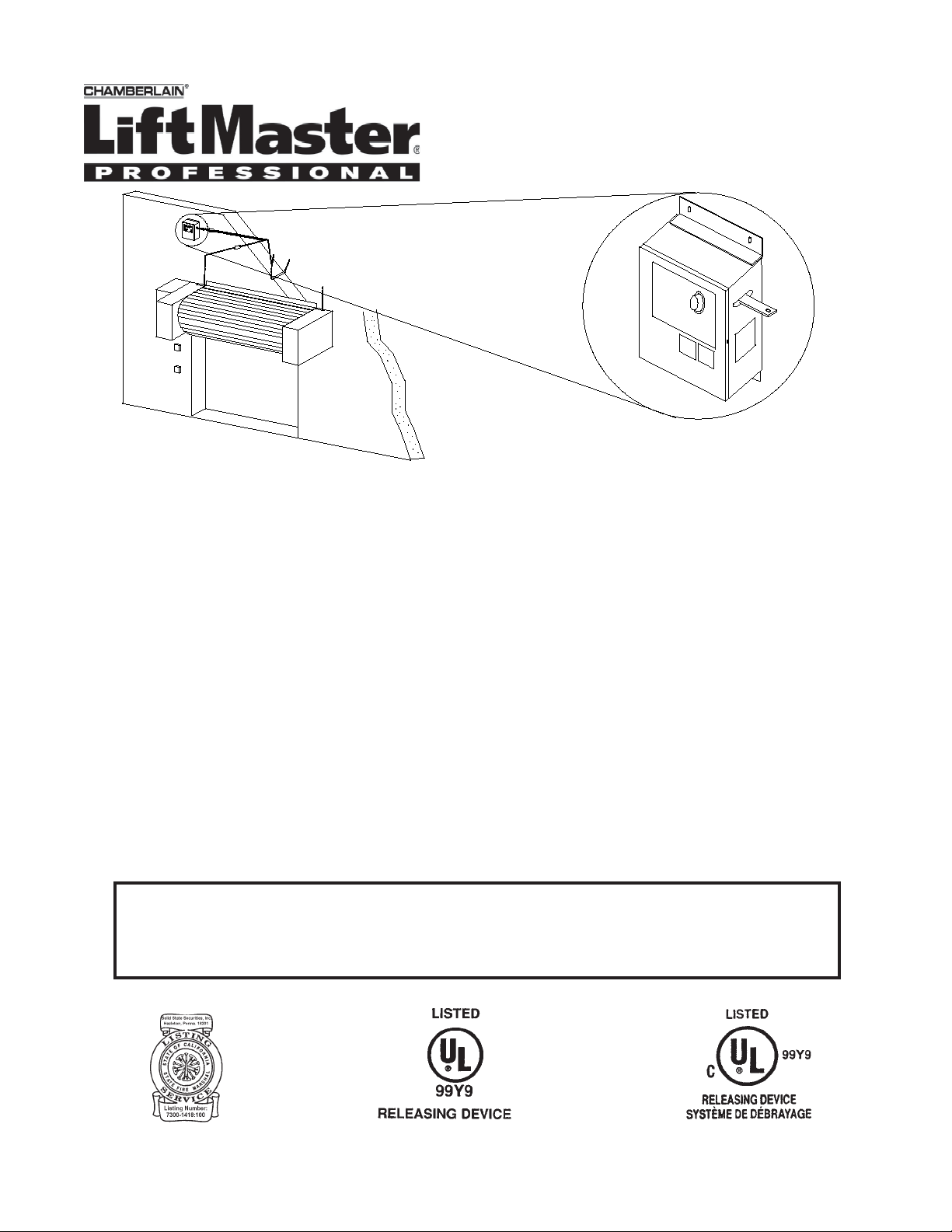
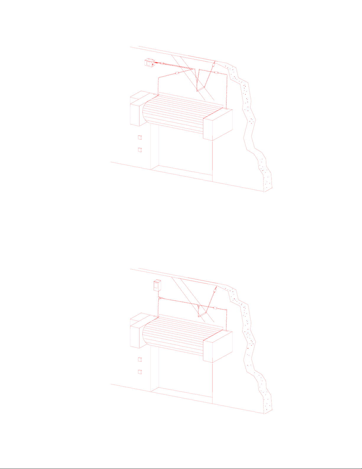
SECTION A. MOUNTING PROCEDURE (Figures 1 & 1A)
1. The release device shall be mounted on a vertical surface with chain end link exiting side of enclosure as illustrated in
figure 1 (horizontal pull) or 1A (vertical pull).
2. Release device enclosure shall be mounted with minimum #10 size fastening screws or bolts for securing to structures
other than masonry. Masonry applications shall utilize 1/4" or greater anchors or studs as required to insure proper
mounting strength.
3. Release device and associated hardware [sash chain or 1/16 cable, eyebolts, fuse links ( do not install this unit without
fuse links), turnbuckles] shall be installed as per door manufacturer recommendations (fig. 1 & 1A typical installation
configura tion). Note should be taken that the end link direction of pull is perpendicular to the enclosure side. An eye bolt
installed at a distance of 18 to 24 inches from the release device should adequately redirect sash chain pull as illustrated
in figures 1 and 1A.
4. Complete hardware installation by connecting fuse links, sash chain, S-hooks and turnbuckles as required. Reset release
device by depressing reset knob in until latch clicks into locking position Push end link into opening of release
mechanism while holding tension from release arm. Release rest knob. Release device is now set.
SECTION B. Smoke Detectors.
When installing smoke detectors with this unit refer to NFPA 72 and NFPA 80, for instructions concerning proper
placement and detection coverage.
SECTION C. ELECTRICAL CONNECTIONS
All models (Figure 3- stand alone, Figure 3A- Delayed Daisy Chain) Installation of all wiring and connections shall be
performed in accordance with, but not limited to, the latest NFPA, UL and NEC standards. In addition, all installations subject
to Canadian standards shall be performed in accordance with the Canadian Electrical Code, Part I, with respect to wiring
material, wiring gauge related to power capacity requirements and circuit length and wiring methods.
I) Stand alone use (Figure 3) The model-RR Release Device, does not provide delay in power loss or alarm. Use Model
RRD if the installation is stand alone and a delay is required
1. Turn off power supply before beginning.
2. Verify voltage rating of release device to power source being utilized.
3. Connect power source inputs (through normally closed initiating device) to red (+) and black (-) wires. Observe proper
polarity. Install chassis ground where applicable. Do not connect (-) to chassis ground.
II) Delayed Daisy Chain -LM90 Series Model LM90-B2 Master. Daisy chain configuration provides time delay feature from
master unit (Model B2 Master). Independent delays are set inside master unit there is a 10 second alarm (factory set) and
battery support for power loss. Use only the LM90-RR in daisy chain configuration to avoid doubling the time delay. DO
NOT use the LM90-RR-24 when using the Daisy Chain configuration.
1) Run two wires (18 gauge) from master unit to first LM90-RR-12. Run two wires (18 gauge) between each Remote.
Maximum of three (3) units.
2) Connect red (+) wire from LM90-RR-12 to wiring from TB1-15 and black wire to wiring from TB2-1. Review Figure 3A for
additional wiring required inside of master unit.
Verify connections made within unit. Close cover and secure screw-on lid after all connections are made.
DO NOT LEAVE COVER OPEN AFTER CONNECTIONS ARE MADE!
2
Page 3
LM90-RR
FIGURE 1
LM90-RRD
Horizontal pull
FIGURES 1 AND 1A DEPICT MOUNTING OPTIONS FOR REMOTE RELEASE AND
ARE NOT PROVIDED AS GUIDELINES FOR THE INSTALLATION OF THE DOOR OR
ASSOCIATED HARDWARE. SEE DOOR MANUFACTURERS RECOMMENDATIONS
AND NFPA 80 FOR USE OF THIS PRODUCT, FUSIBLE LINKS AND ASSOCIATED
HARDWARE USED WITH SPECIFIC DOOR. ACTUAL CONFIGURATION MAY VARY
SIGNIFICANTLY FROM ILLUSTRATIONS PROVIDED.
LM90-RR
LM90-RRD
Vertical pull
FIGURE 1A
3
Page 4

LM90-RR INSIDE VIEW (Cover removed) FIGURE 2
Reset Knob
Power LED
(+)
(1) Input power
(-)
(1) Verify input voltage to model being used.
(2) See NFPA 80 and NFPA 72 for proper placement.
Manual Test Button
FIGURE 3 - ELECTRICAL WIRING
(2) Initiating Device (Smoke detector, etc.)
RED
BLACK
LM90-RR (REMOTE RELEASE)
LM90-RRD (DELAY OPTION)
(+)
(-)
Chassis ground
Installation of all wiring and related connecting hardware must be performed in accordance with the latest NFPA, UL, and NEC standards and
codes. In addition, all installations subject to Canadian standards shall be performed in accordance with the Canadian Electrical Code, Part I, with
respect to wiring material type, wiring gauge related to power capacity requirements and circuit length and wiring methods.
4
Page 5

FIGURE 3A - ELECTRICAL WIRING : TIME DELAY DAISY CHAIN CONFIGURATION
SMOKE DETECTOR
OR ALARM PANEL
(5)
NORMALLY CLOSED
DRY CONTACT LOOP
(2)
LM90-B2 Master
TB-1
18
(3)
(+)
1
1
2
3
RED
(+)
BLACK
LM90-RR
#3
(-)
RED
(+)
BLACK
LM90-RR
#2
(-)
14
15
(4)
(+)
RED
BLACK
LM90-RR
#1
(1)
(-)
18
1
(-)
2
TB-2
Refer to page 1, Section C for wiring descriptions.
Wiring of the remote releases in a Daisy Chain configuration to a master unit provides time delayed release with simultaneous closure on all
doors. A maximum of three (3) units may be daisy chained from the master unit.
(1) Verify model being used as LM90-RR-12. Do not use LM90-RR-24.
(2) See NFPA 80 and NFPA 72 for proper placement. Electrical supervision of detector shall be provided as per U.L. 864
(3) Install jumper between TB2-2 and TB1-14 of master unit.
(4) Wiring between units is parallel connected. DO NOT series connect units.
(5) Illustration does not depict entire master unit. See installation manual of master unit for additional information.
Installation of all wiring and related connecting hardware must be performed in accordance with the latest NFPA, UL, and NEC standards and
codes. In addition, all installations subject to Canadian standards shall be performed in accordance with the Canadian Electrical Code, Part I, with
respect to wiring material type, wiring gauge related to power capacity requirements and circuit length and wiring methods.
5
Page 6

"LM90" SERIES RELEASE DEVICE ELECTRICAL AND MECHANICAL CHARACTERISTICS
ELECTRICAL RATINGS
MODEL (D- delay option) VOLTAGE MIN. MAX. CURRENT
LM90-RR-12 / LM90-RRD-12 12VDC 10.2 15.0 .050A
LM90-RR-24 / LM90-RRD-24 24VDC 20.0 28.0 .050A
MECHANICAL- LOAD RATING DIMENSIONS
Support and release: 40LB. MAXIMUM 6" x 4 " x 3 1/8" (H x W x D)
SECTION D. TEST PROCEDURES
TO BE PERFORMED BY FACTORY AUTHORIZED PERSONNEL ONLY! REGULAR TESTING OF ALL RELEASE DEVICE
EQUIPMENT IS RECOMMENDED. TESTING SHALL BE WITNESSED FOR PROPER OPERATION.
Testing does not affect normal operation of alarm system when connected to release device. Testing and normal operation can
only be accomplished with power applied to unit. When power is applied to unit under test the Power LED (red) will be lit on
the bottom of the release device.
CLEAR FIRE DOOR OPENING AND PROHIBIT ALL TRAFFIC THROUGH DOOR OPENING DURING TESTING OF SYSTEM!
Door must be in open position with power applied to unit and/or master unit on Daisy chain configurations.
A.) Stand alone use LM90-RR.
1. Depress test button on side of release device (figure 1). LM90 release device will immediately release door.
Release test button.
2. Reset and raise door. Reset release device by depressing reset knob in until latch clicks into locking position
Push end link into opening of release mechanism while holding tension from release arm. Release rest knob.
Release device is now reset. Allow a minimum of 25 seconds between tests of release device.
B.) Stand alone use LM90-RRD (Delayed unit)
1. Depress and continue to hold test button on side of release device (figure 1). After 10 sec. (+/- 2 sec.) delay unit
will release door. Release test button.
2. Reset and raise door. Reset release device by depressing reset knob in until latch clicks into locking position
Push end link into opening of release mechanism while holding tension from release arm. Release rest knob.
Release device is now reset. Allow a minimum of 25 seconds between tests of release device.
C.) Daisy Chain use. Model LM90-RR only.
1. Depress and continue to hold chassis mount test button on master unit. After 10 second delay (factory adjusted)
all Remote Releases will close simultaneously. Reset as described above.
Allow a minimum of 25 seconds between tests of release device.
After completing all tests, make sure door is in its normally open position and all power required for normal operation is
restored to unit. This unit is designed to operate with power applied.
REMINDER:
Testing of the "LM90-RR" release device is independent of, and shall in no way be interpreted as an alternative method of,
testing of the fire alarm system, motorized operator and/or any other system component employed on the fire door or counter
fire door installation. TESTING SHALL BE PERFORMED AND WITNESSED FOR PROPER OPERATION.
MAINTENANCE REQUIREMENTS
The Remote Release Devices have no scheduled maintenance requirements. The unit has been designed and tested for use in
indoor locations. Regular testing of the unit is recommended. Testing should be performed a minimum of once annually as per
appropriate standards, but test intervals shall ultimately be subject to criteria established by the Final Authority Having
Jurisdiction (AHJ).
Should servicing of equipment be required, personnel authorized to perform such maintenance shall ensure that; a) all traffic is
prohibited through door opening, b) door is mechanically released and fully closed, c) all power is disconnected from unit. After
servicing equipment as required, unit shall be tested and witnessed for proper operation as described in SECTION D- TEST
PROCEDURES, contained herein.
6
Page 7

LM90-RR & LM90-RRD TROUBLESHOOTING GUIDE
Verify that desired options are available on unit before troubleshooting. Refer to electrical connection information and wiring
diagrams of this manual. Troubleshooting shall be performed by factory authorized personnel only. Service and/or installation
by unauthorized personnel shall void warranty. Review the following guide prior to requesting technical support.
Daisy Chain configuration, call tech support before troubleshooting. If technical support is required, unit serial number
(found on front of manual and inside unit), as well as distributor who supplied unit must be provided. Should servicing of
equipment be required, personnel authorized to perform such maintenance shall ensure that; a) all traffic is prohibited through
door opening, b) door is mechanically released and fully closed, c) all power is disconnected from unit. After servicing
equipment as required, unit shall be tested and witnessed for proper operation as described in SECTION D-TEST PROCE-
DURES, contained herein.
When using
SYMPTOM
1. Red Power LED does not light.
2. Red LED is on, but unit does not release
door after alarm or power loss delay.
3. Red LED is on, unit does not respond to
manual test button, but works in alarm.
POSSIBLE TROUBLE
A) Primary power source turned off.
B) Loose connection on Red or Black wire
C) Incorrect polarity on unit
D) Master unit fuse blown. Call tech support.
E) Incorrect power source applied. Verify voltage
and call tech support.
A) Power loop is not connected to proper power
source. Disconnect Red and Black wires.Measure
power source.
10.2-15V LM90-RR-12
20.6-30V LM90-RR-24
B) N/C Alarm loop not opening. Place smoke detec
tor in alarm and verify that contacts open on alarm
disconnecting power.
C) Wiring incorrect on Daisy Chain master unit.
Call tech support.
D) Load on Release mechanism exceeds 40lbs or is
not pulling perpendicular to unit.
E) Damaged unit. Call tech support.
A) Test button is not being depressed long enough
on Master unit or individual unit. Press button
continuously for the 10 second delay (RRD). Unit
must be powered up for a minimum of 25 seconds
before initial test and between subsequent tests.
B) Possible defective switch. Call tech support.
7
Page 8

Warranty Service Procedure
Contact technical support at the number provided below for assistance in determining possible product failure. Installer
shall provide the following information when contacting technical support:
1) Unit Serial Number, found in the following locations
a) Individual unit shipping box
b) Cover of installation manual
c) On unit
2) Name of Distributor who supplied product
3) Name of End User and/or installation company if different from Distributor
4) Detailed description of product non conformity
To receive a Return Goods Authorization (RGA) and shipping address for a Product believed to be defective, all of the above
information shall be required. Products returned without a valid RGA shall be refused receipt. If provided, reference
troubleshooting guide that accompanies product prior to requesting an RGA.
Contact Information
Technical Support: 1- 888-528-7870
RGA (631)467-2501, Request Customer Service
01-30633A ; 2003, The Chamberlain Group, Inc.
All rights Reserved
 Loading...