

Page 1
RELEASE DEVICES
MADE IN THE U.S.A.
ADVANCE FIRE CONTROL MODEL LM21-AFC MANUAL
The LiftMaster Fire Control (LM21-AFC) Release Device/Control Panel is UL/CUL listed normally energized fail-safe device
incorporating state of the art electronic control circuitry. The LM21-AFC is designed to be used with manual doors or motorized
doors incorporating a reversing feature safety edge to create an automated door closing system.
DO NOT install this unit on a motorized door without a safety edge.
The LM21-AFC high performance control panel responds to emergency conditions generated by manual or automatic initiating
devices. Upon activation from such a device, the unit will then automatically close a motorized door or release a manual door. If
the alarm is still present and power is available to the operator, a motorized door can be opened by depressing the open switch of
the operator, after which the door will close again. If the door meets an obstruction while in alarm, the door will reverse and make
three attempts to close, after which the motor will be shut off and the door will rest on the obstruction or the LM21-AFC can be
optionally set to open to the limit and subsequently mechanically release the fire door onto the obstruction. The unit can be factory
ordered with cycle count from 1 through 10 (3-count standard), as well as continuous cycling capability. A safety timer within the
unit will turn the motor off and perform a mechanical release if the lower limit is not detected within a predetermined time period.
Verify factory-installed options to desired features during initial testing.
The LM21-AFC features include a selectable 10-second or 20-second time delay on alarm, remote test, motor voltage sensing,
form-C relay output, lower limit detection, safety timer, battery support for release device logic, smoke detectors, standard
annunciators and trouble diagnostic capabilities (does not support motor). Operating voltage is 120 VAC.
CAUTION: Review all installation instructions, procedures, referenced publications, cautions and warnings contained within this
manual prior to installing and/or servicing this product. As with all releasing device systems, maximum fire protection is provided
when installed in accordance with factory specifications and used with fuse link systems.
DO NOT install this unit without a fuse link system.
TEST WEEKLY TO ASSURE PROPER OPERATION OF RELEASE DEVICE/CONTROL PANEL
Installation and testing to factory specifications shall be performed by factory authorized personnel for proper operation in
accordance with the latest National Fire Protection Association (NFPA), Underwriters Laboratories (UL), National Electrical Code
(NEC), local, state, county, district and/or other applicable building and fire standards, guidelines, regulations and codes including,
but not limited to, all appendices and amendments and the requirements of the local authority having jurisdiction (AHJ).
Page 2
INSTALLATION INSTRUCTIONS – Installation to be performed by factory authorized personnel only. The following installation
procedures must be followed to assure performance of the LM21-AFC Release Device/Control Panel to factory standards.
MOUNTING PROCEDURE
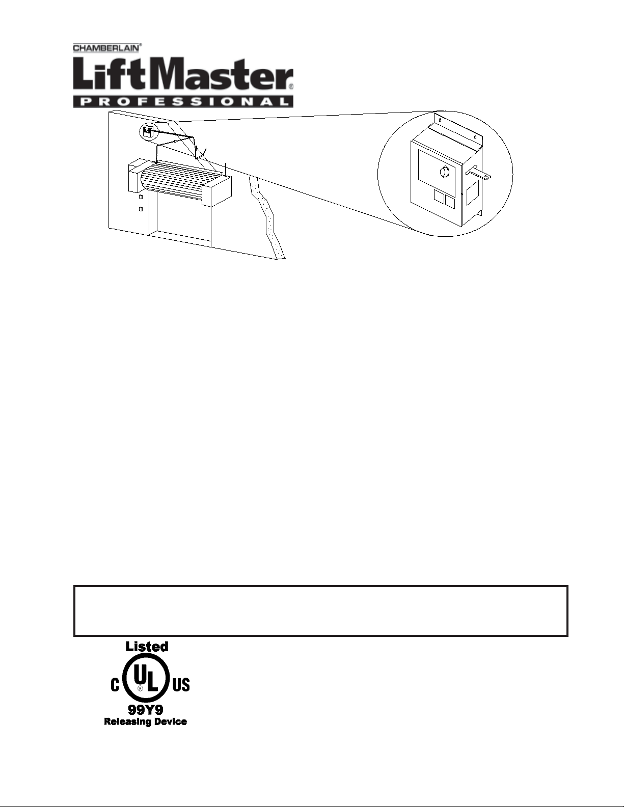
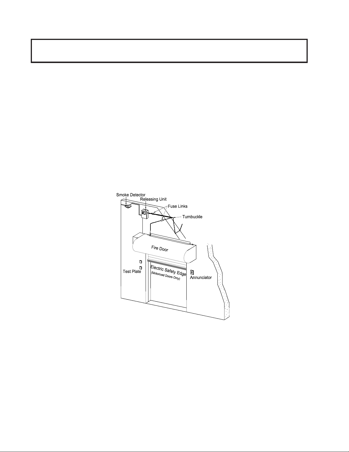
Typical installation configuration (figure 1) may not accurately depict door manufacturer’s recommendations. See door
manufacturer’s recommendations for use of this product with specific door being utilized. The door installer or manufacturer shall
supply all hardware required. Use only hardware approved or recognized by the appropriate testing and listing agencies in
conjunction with the installation of this product. (Figure 1)
1. The release device shall be mounted on a vertical surface with chain end link exiting side of enclosure as illustrated in
Figure 1.
2. Release device enclosure shall be mounted with minimum #10 size fastening screws or bolts for securing to structures other
than masonry. Masonry applications shall utilize 1/4" or greater anchors or studs as required to insure proper mounting
strength.
3. Release device and associated hardware (sash chain or 1/16 cable, eyebolts, fuse links, turnbuckles) shall be installed as per
figure 1 or door manufacturers recommendations. Note should be taken that the end link direction of pull is perpendicular to
the enclosure side. An eyebolt installed at a minimum distance of 12 inches from the release device should adequately
redirect sash chain pull as illustrated in Figure 1. DO NOT use this device without fuse links installed.
4. Complete hardware installation by connecting fuse links, sash chain, S-hooks and turnbuckles where required. Press
mechanical reset plunger in to allow insertion of end link through release device side opening. Push end link completely in
and release mechanical reset plunger to latch end link. Remove sash chain or cable slack by adjusting turnbuckle.
* DO NOT exceed maximum pull rating of 40 lbs. on releasing device.
SMOKE DETECTOR INSTALLATION
When installing smoke detectors with this unit refer to NFPA 72 and NFPA 80, paragraph 6-6, for instructions concerning proper
placement and detection coverage. See the Electrical Connections sections for wiring information. End of Line Devices shall be
installed for supervision of electrical power to 4-wire smoke detector. DO NOT interface this unit to 4-wire smoke detectors if
electrical supervision is not provided by means of a UL/CUL listed End-of-Line Device used in conjunction with the LM21-AFC.
ELECTRICAL CONNECTIONS
Installation of all wiring and connections, including Class 1 and Class 2 circuits, shall be performed in accordance with, but not
limited to, the latest NFPA, UL and N.E.C. standards and codes. In addition, all installations subject to Canadian standards shall be
performed in accordance with the Canadian Electrical Code, Part I, with respect to wiring material type, wiring gauge related to
power capacity requirements and circuit length and wiring methods. This unit is designed to be used on manual doors or motorized
doors incorporating a reversing feature safety edge.
DO NOT use this unit on a motorized door if a safety edge has not been installed.
2
Page 3
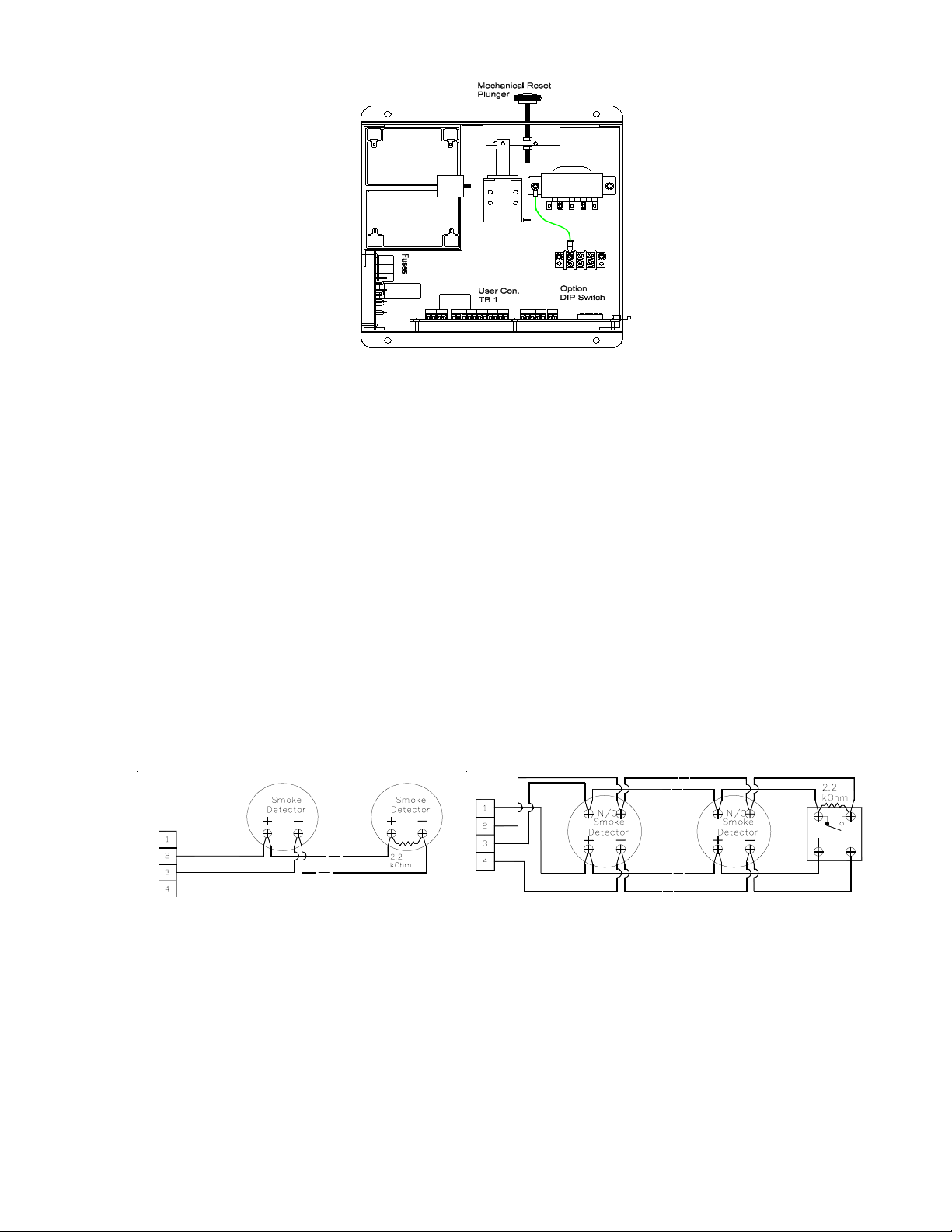
Figure 2 - Interior View
SEE Figures 2 through Figure 7
Verify wiring configuration with that recommended by door manufacturer for use of this product with specific door and
accessories being utilized. All wiring beginning at step 4 is low voltage. 18-gauge wire is recommended.
1. Turn off power supply sources for the LM21-AFC as well as the door operator before beginning.
2. Verify voltage rating of power source being utilized is 120 VAC. Verify that power is disconnected at fuse box before proceeding!
3. Connect 120 VAC (single phase) power source inputs to TB2, “Hot” to screw 1 and “Neutral” to screw 2. TB2, screw 3 shall
be utilized for earth ground where applicable (Figure 2). Do not connect battery at this point.
4. Initiating devices (All operators) Note: There is a 4-detector maximum.
a) Normally open “2-Wire”, class B style A, 12V DC initiating devices - remove supervisory resistor from positions 2 &
3. Connect wiring from N/O initiating device loop to positions 2 & 3. Place UL/CUL listed supervisory resistor (2.2k
Ohm @ ¼ Watt) across the terminals of the last initiating device as illustrated in Figure 3. Observe proper polarity, 2
(+), 3 (-). Wiring is illustrated in Figure 3. (Supervised, current-limited circuit)
b) Normally open “4-Wire” class B style A initiating devices - Connect wiring from N/O 4-Wire initiating device loop to
positions 2 & 3, making sure UL/CUL listed end-of-line supervisory resistor (2.2 K ohm @ ¼ Watt) is installed at a UL/
CUL listed end-of-line relay. (Do not share alarm loop with other alarm circuits). +12V DC Auxiliary power for smoke
detectors may be obtained from 1 for +24V DC. Ground can be obtained from 4. Wiring is illustrated in Figure 4, there is
a 4-detector maximum and an end of line relay device must be used as per UL 864. (Supervised, current-limited circuit)
Note: End of line devices must be installed adjacent and after the last initiating device. Initiating device loops are supervised
and cannot be directly series or paralleled between multiple release devices or shared with other alarm equipment. For proper
wiring configurations from multiple smoke detectors or signaling for simultaneous closure on multiple doors call technical
support (
Figure 3 – Two-Wire Smoke Detector Wiring Figure 4- Four-Wire Smoke Detector Wiring
a) Auxiliary Lower Limit switch (All operators). Connect wiring from N/O electrical loop (switch closed when door is closed) to
b) Auxiliary Upper limit switch (Motorized doors only). Connect wiring from N/O electrical loop (switch closed when door is up)
570-450-6613). Incorrect wiring between units may cause damage to the release control circuit and void warranty.
5. Operator Connections. Make the remainder of connections to the operator as illustrated in Figure 6. Note: When used
on motorized doors, the LM21-AFC requires an electric safety edge.
6. Connect motor control sensing voltage (24-30V ac or dc) from motor controller transformer (motorized doors only)
secondary to screws 11 (+) & 12 (-). This connection must be made or the unit will perform a mechanical release in all
alarm conditions when the door is not closed. (Figure 6)
7. Limit Switches – Figure 5.
13 & 14. This input precludes the door mechanism from releasing if a lower limit is detected (door is already closed). This
circuit also turns off sounders in down limit. (Current-limited circuit)
to 14 & 15. Connection to an auxiliary up limit switch is required for 3-cycle obstruction count feature. Set aux. limit to toggle
3
Page 4

before operator limit when door is traveling toward open position. (Supervised, current-limited circuit) Note: Electrical loops
must be provided as dry contacts and may not be used in conjunction with the simultaneous switching of a motor control or
any other voltage through the same contacts. Connections of this type will result in immediate damage to the release device.
Figure 5 Auxiliary Limit Switch Connections
8. Motor control relay (Motorized doors only) - Connect wiring from 7,8,9 & 10 across motor control 3-button station (For use
with N/O ‘Close’ switch, N/O ‘Open’ switch and N/C ‘Stop’ switch). The Close relay output latches to initiate a door closure
through the operator after a 10-second delay (20-sec. Optional). (Figure 6) The Open relay is used to open the door when
the Auto-Open feature is enabled.
Figure 6 - Operator Electrical Connections
9. Remote test station. - (Optional) This optional device (part number SSRT) disables the cycle counter to allow testing of the
door without a mechanical release after 3 cycles. Connect N/O remote test switch common to 21 and 22 as illustrated in
Figure 7. (Current-limited circuit)
10. Annunciator - (Optional) Connect annunciator (part number SSHS2475ADA) to 16 (+) & 20 (-) as illustrated in Figure 7.
UL/CUL listed end-of-line resistor (2.2k Ohm @ ¼ Watt) must be placed installed as illustrated. Multiple annunciators may
be connected but the maximum output current of the devices must not exceed .75A DC. (Supervised, current-limited circuit)
11. Additional dry contact relay is provided between 17 (Input) and 18 (N/C Output) and 19 (N/O Output) as illustrated in
Figure 7. Maximum switched current is .5A 125V AC, .2A 110V DC, 1A 24V DC. Switching of this relay occurs
immediately upon sensing an alarm.
Figure 7 - Electrical Connections for Annunciator and Test Plate
4
Page 5

DIP-Switch Options
The LM21-AFC has six DIP-switch selectable options. The options DIP-switch is located next to terminal block 5 as illustrated in
Figure 2. Note: switches 7 and 8 are currently unused. Set all DIP-switch options before applying power to the system. The
selection of positions is listed below.
hctiwSPID
noitisoP
1 htiwroodehtesolcottpmettalliwCFA-12MLehT.rooddezirotoM
2 lliwCFA-12MLeht,desusirooddezirotomafI.noitcurtsbOnopotS
302aevahlliwCFA-12MLehT.noitcaerofebyaleDdnoces-02
.pordroerusolc
4 6retfaroodehtpordlliwCFA-12MLehT.remitytefasetunim-6
5 hcihw,mralanasarewopenilfossolataerT.mralassolrewopeniL
6mralaretfayllacitamotuarooddezirotomanepO.nepO-otuA
7.desutoN .desutoN
8.desutoN .desutoN
.gnisaelererofebrotomeht
.emitdrihtehtdesnessiti
.deraelcsinoitidnoc
'nO'hctiwS 'ffO'hctiwS
siegdeytefasehtfiesreverlliwtubroodehtesolcottpmetta
nehwnoitcurtsboehtnoroodehtpotslliwCFA-12MLehT.dereggirt
roodagnimrofreperofebdesnessimralanaretfayaleddnoces
.erusolcdezirotomaybdeveihcatonsitimilesolcfisetunim
.pordro,erusolcroodotsdael
.rotomahtiwtiesolcotgnitpmetta
)dradnatS(.pordroerusolc
)dradnatS(
)dradnatS(.deraelc
tuohtiwroodehtpordlliwCFA-12MLehT.roodlaunaM
CFA-12MLehT.semiteerhtnoitcurtsbonagnisnesretfaporD
.roodehtpordnehtdnadesnessinoitcurtsbo
drihtaretfaroodehtnepoylluflliwCFA-12MLehT.dereggirt
01aevahlliwCFA-12MLehT.noitcaerofebyaleDdnoces-01
.erusolcdezirotomaybdeveihcatonsitimilesolcfisetunim
.tsolsirewopenilnehwrewopyrettabmorfyllamronetarepO
Testing
Note: Battery should NOT be connected until testing of unit is being performed. Testing of release device/
control panel shall be performed and witnessed for normal operation after installation. Refer to test
procedures contained herein, as well as any other testing programs recommended by door manufacturer.
siegdeytefasehtfiesreverlliwtubroodehtesolcottpmettalliw
roodagnimrofreperofebdesnessimralanaretfayaleddnoces
3retfaroodehtpordlliwCFA-12MLehT.remitytefasetunim-3
sinoitidnocmralaretfadesolcroodpeeK.delbasiDnepO-otuA
TO BE PERFORMED BY FACTORY AUTHORIZED PERSONNEL ONLY! CLEAR FIRE DOOR OPENING AND PROHIBIT
TRAFFIC THROUGH DOOR OPENING WHILE TESTING! Testing does not affect normal operation of alarm system when
connected to release device/control panel. Testing of the LM21-AFC is independent of, and shall in no way be interpreted as
an alternative method of, testing of a central fire alarm system, motorized operator and/or any other system component
employed on the fire door or counter fire door installation. Complete testing and normal operation can only be accomplished
with power applied to unit. This procedure describes testing of all options. Verify options ordered and installed with unit. All
tests may not apply. Refer to Figure 9 for buttons and LED’s mentioned in this section. POWER UP SEQUENCE: Be sure
to follow proper sequence. Turning motor on before unit, or at the same time as unit, will result in a closure through the
motor. This is a normal condition when proper sequence is not followed. If a single electrical disconnect is provided for both
motor and unit, have door in down limit when energizing. Turn on power to unit. When power is applied to unit the Power
LED (Figure 9 e) will light on the bottom of the release device and the battery trouble sounder will begin to beep. Connect
battery leads as illustrated in Figure 8 using the included battery interconnect wire and the LM21-AFC battery wires. Green
LED (Figure 9 d) will light indicating battery is connected and charging. Turn on power to motor. Motor Sense Disable yellow
LED (Figure 9 c) will light indicating power is present at motor control secondary.
Figure 8 - Battery Connections
5
Page 6

TEST PROCEDURES
Automatic Door Closure Tests (Motorized Doors Only)
1. Enclosure mounted test switch: Depress and continue to hold test button on side of release device/control panel (Figure 9).
Annunciator will turn on indicating a door closure is about to occur and after 10-second alarm verification delay, delay relay will
initiate a door closure. Optional annunciator will turn off when door makes lower limit. Release test button. Depress “Open” button
on door control to raise door to open position.
2. Remote test station: This test disables the internal counter circuit and allows the door to continuously cycle if a suitable obstruction
is utilized for such a test (See step 4). Insert key into remote test station and turn key in direction of test indicator. Annunciator will
turn on and a door closure will occur immediately (no delay is provided). If no obstruction is placed in the path of the descending
door, the door will fully close and the motor will turn off. If an obstruction is used, the door will close until it strikes the obstruction
and subsequently reverse to a fully open position. This door will immediately begin to close again and continue this cycle until the
key is returned to the off position. Return test switch to off position to silence test sounder, leaving the door closed.
3. Down limit detection: With door closed, depress and hold enclosure mounted test switch. Annunciator will not turn on; indicating
the door is already in the closed position. Release test button. Depress “Open” button on door control to raise door to open position.
4. Three-Cycle Obstruction test: WARNING! THIS EQUIPMENT IS DESIGNED TO BE USED IN CONJUNCTION WITH
AN OPERATOR INCORPORATING A REVERSING FEATURE SAFETY EDGE. DO NOT EXECUTE THIS TEST
WITHOUT A SAFETY EDGE INSTALLED! Place a chair or other suitable obstruction in the normal path of the door. Stand
clear from opening. Depress and continue to hold down the enclosure mounted test button. The annunciator will turn on indicating
that a door closure is about to occur. After factory set 10-second delay (or optional 20-second delay), the device will turn on the
motor initiating a closure. Upon contact with the suitable obstruction being utilized, the safety edge will reverse the motor raising the
door to the open position. The LM21-AFC will make three (3) attempts to close through the motor, after which the LM21-AFC will
turn off the motor when the door reaches the open position and release the door through the drop release mechanism. The LM21AFC can optionally be set to stop the door on the obstruction after the third triggering of the safety edge (See DIP switch options).
The door will stop on the obstruction and will close fully after the obstruction is removed. The annunciator will continue to sound
until the alarm condition has been cleared. Release test button. Reset fire door release mechanism, and then reset LM21-AFC release
mechanism by pushing in the mechanical reset plunger. Insert end link through enclosure opening and release reset plunger latching
the end link. Depress open button on motor control raising door to open position.
Mechanical Door Drop Tests (All operators)
1. Make sure door is fully raised. Interrupt (turn off) power to motor operator.
2. Note that Mechanical Release Disabled LED (yellow) is off on side of release device indicating “power is off to
motor” and the door is not closed. Depress and continue to hold the “Test” button on side of release device.
Annunciator will sound indicating a door closure is about to occur and after factory set 10-second alarm verification
delay (or 20-sec. optional) device will release door. Release “Test” button. This test verifies a mechanical release
in absence of power to the motor.
3. Reset fire door release mechanism, then reset LM21-AFC release mechanism by pressing mechanical reset
plunger. Fully insert end link through release device side opening and release mechanical reset plunger to latch
end link.
4. Restore power to the motor and raise door to its fully open position. Press the “Reset” button on the side of the
LM21-AFC unit.
5. After completing all tests, verify that door is in its normal condition (open or closed) and that all power required for
normal operation is restored to unit and operator. The equipment is designed to operate with its primary power
source applied.
Figure 9 - Exterior View of Buttons, Mechanical Reset Plunger and Status LED’s
6
Page 7

Figure 10 - LED Description
DELroloCDELnoitpircseDderiuqeRnoitcA
lacinahceM
esaeleR
delbasiD
)9erugiF(
yrettaB
tneserP
)9erugiF(
rewoPeniL
tneserP
)9erugiF(
nepO
)01erugiF(
trohS
)01erugiF(
timiLnepO
)01erugiF(
deRdnadetcennocsirewopenilehT
rotaicnunnA
rotaicnunnA
deR-trohssitiucricrotaicnunnAehT
wolleY
neerGdellatsnineebevahseirettaB
wolleYnodellatsnitonsirotsisermhOk2.2
neerGdereggirtasesnesCFA-12MLehT
.roodehtesaelertonlliw
.degrahcyllufneeb
."no"dehctiws
.detiucric
.hctiwstimilnepoyllamron
tierehwetatsanisiCFA-12MLehT
evahrognigrahceradnayltcerroc
sthgilDEL:etoN.tiucricrotaicnunnA
.noitidnocmralanisimetsysnehw
01dna9serugiF(srotacidnIDELCFA-12ML)
nagnisnesybrotimilesolcnigniebybdesuacsisihT
dnasnoitcennochctiwstimilkcehC.rotareporoodcirtcele
.
)6erugiF(snoitcennocegatlovlortnocrotareporotom
dnaseirettabehtgnillatsniretfanoemoctonseodDELfI
.8erugifnidetartsulli
.3petssnoitcennoClacirtcelE
.)7erugiF(01noitcesnoitallatsnI
.)7erugiF(01noitcesnoitallatsnI
saerasnoitcennocyrettabkcehc,rewopgniylppa
tahtkcehc,deilppasirewopnehwthgiltonseodDELfI
nidebircsedsa)2erugiF(2BTotretcennocsirewop
nidebircsedsadellatsnisirotaicnunnAehttahtkcehC
nidebircsedsadellatsnisirotaicnunnAehttahtkcehC
fI.ylreporpdetcennocsitupni,timilnepOnisiroodfI
timilyrailixuatahtkcehc,timilnepOnitonsirood
.5erugiFnidetartsullisaedamerasnoitcennoc
timiLesolC
)01erugiF(
rotceteD
nepO
)01erugiF(
rotceteD
trohS
)01erugiF(
neerGdereggirtasesnesCFA-12MLehT
wolleY
deR-trohssitiucricrotcetedekomsehT
.hctiwstimilesolcyllamron
.tiucricrotcetedekoms
.detiucric
nodella-tsnitonsirotsisermhOk2.2
.4erugiFro3erugiFnidetartsullisatiucric
.srotcetedehtteserehtnottub"teseR"
fI.ylreporpdetcennocsitupni,timilesolCnisiroodfI
timilyrailixuatahtkcehc,timilesolCnitonsirood
.5erugiFnidetartsullisaedamerasnoitcennoc
ehtnidetcennocsirotsisermhOk2.2atahtkcehC
ehtnidetcennocerasrotcetedekomSehttahtkcehC
ehtsserP.4erugiFro3erugiFnidetartsullisatiucric
7
Page 8

Specifications
SNOITACIFICEPSLACIRTCELELENAPLORTNOC/ECIVEDESAELERCFA-12ML
gnitaRegatloV
stnemeriuqeRtnerruC
gnitaRyrettaB
eciveDgnitaitinI
sesuF
esneSlortnoCrotoM
rewoPyrailixuA
)gnitaRtcatnoC.xaM(tuptuOCmroF
gnitaRdaoL
snoisnemiDlacisyhP
)seirettaBsedulcnI(thgieW
zH06,CAV021
XAMA057.mralAA001.)mrala-non(yrosivrepuS
seirettabdicadaelHA5.4V21owT
smhO001:ecnatsiserpoolmumixaM
CDV42:egatlovmumixaM
mumixamA57.@CDV42
)DxWxH("5x"01x"01
.sbl81yletamixorppA
A010.deecxeottoN:tnerrucmumixaM
epyTwolB-wolSGA2,V052@A2sesufllA
-/%51+lacipytCD/CAV42:egatloVtupnI
A400.deecxeottoN:tnerruCtupnI%01
CDV42A1,CDV011A2.,CAV521A5.
SNOITACIFICEPSLACINAHCEMLENAPLORTNOC/ECIVEDESAELERCFA-12ML
mumixaM.bl04:esaeleRdnatroppuS
HOW TO ORDER REPAIR PARTS
INSTALLATION AND SERVICE INFORMATION AVAILABLE
FROM THE TECHNICAL PARTS AND SERVICE CENTER
ARE AVAILABLE 6 DAYS A WEEK
CALL OUR TOLL FREE NUMBER - 1 (888) 528-7870
HOURS 7:00 TO 3:30 p.m. (Mountain Std. Time)
MONDAY Through SATURDAY
01-19331A
WHEN ORDERING REPAIR PARTS
PLEASE SUPPLY THE FOLLOWING INFORMATION:
PART NUMBER DESCRIPTION MODEL NUMBER
ADDRESS ORDER TO:
THE CHAMBERLAIN GROUP, INC.
Electronic Parts & Service Dept.
2301 N. Forbes Blvd., Suite 104
Tucson, AZ 85745
2003, The Chamberlain Group, Inc.
;
All rights Reserved
 Loading...