

Page 1
Installation Manual Addendum
MODELS
FF SS XX PP -- FF LL RR
FF SS XX PP BB BB -- FF LL RR
FF SS XX PP BB BB VV BB -- FF LL RR
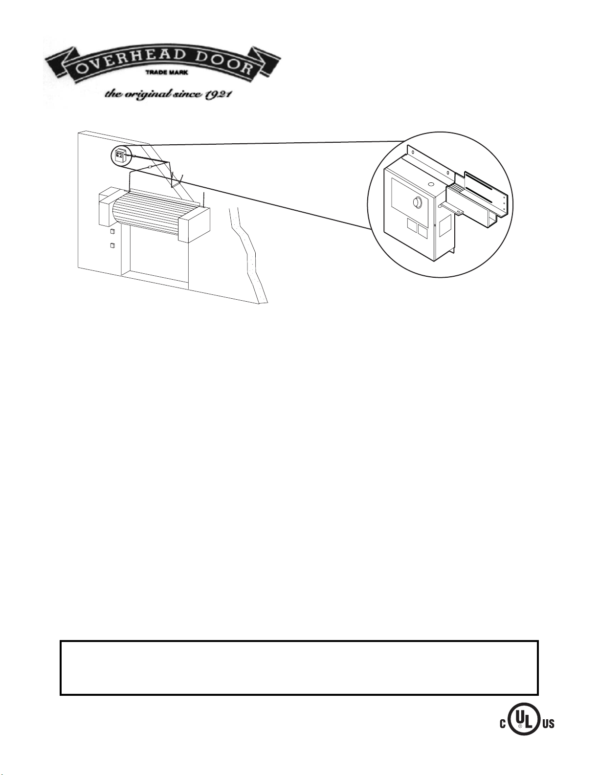
FIRE SENTINEL FLOOR RESET
Reset Mechanism
Overhead Door Corporation
Pennsylvania Division
23 Industrial Park Road
Lewistown, Pennsylvania 17044
Phone: (800) 929-2553
(717) 248-0131
Fax: (717) 248-6447
Installation and testing to factory specifications shall be performed by factory authorized personnel for proper operation in
accordance with all of the latest National Fire Protection Association (NFPA), Underwriters Laboratories (UL), National Electrical Code
(NEC), local, state, county, district and/or other applicable building and fire standards, guidelines, regulations and codes including,
but not limited to, all appendices and amendments and the requirements of the local authority having jurisdiction (AHJ).
Page 2
GENERAL DESCRIPTION
The Fire Sentinel Floor Reset is a factory installed option on the
FSXP-FLR, FSXPBB-FLR and FSXPBBVB-FLR Release Devices.
The reset Mechanism enhances the standard releasing device by
providing a captured end link, which is easily reset from ground
level after a door release by means of a push-pull cable assembly.
The reset mechanism has been designed for use with the Grifco
fire door hoist, and is ideally suited for use on all doors and
shutters requiring frequent testing.
NOTE: This addendum serves as a supplement to the Fire Sentinel
release device manual. Review all installation instructions,
procedures, cautions and warnings contained within this
addendum as well as the unit installation manual prior to
installing and/or servicing this product. As with all release device
systems, maximum fire protection is provided when installed in
accordance with factory specifications and used with fuse link
systems.
Test system regularly to assure proper operation.
INSTALLATION INSTRUCTIONS ADDENDUM
Installation procedures, and door manufacturer instructions, must
be followed to assure performance of the release device/reset
mechanism to factory standards. To be performed by factory
authorized personnel only.
MOUNTING PROCEDURE (Figure 1)
1. The release device shall be mounted on a vertical surface with
chain end link exiting side of enclosure. The unit may be
rotated 90 degrees CW for a direct vertical pull.
2. Secure the release device enclosure with fastener (#10 is the
minimum size recommended). If installing in masonry, use
concrete anchors (not provided).
3. Release device and associated hardware [sash chain or 1/16
cable, eyebolts, fuse links (Do not install this unit without fuse
links), turnbuckles] shall be installed as per door
manufacturers recommendations (Figure 1). End link direction
of pull should be perpendicular to the enclosure side. An
eyebolt installed at a distance of 18" to 24" from the release
device should adequately redirect sash chain.
4. Connect fuse links, sash chain, S-hooks and turnbuckles as
required. Remove sash chain slack by adjusting turnbuckle.
RESET CABLE MOUNTING PROCEDURE (Figure 2)
1. Reset cable mounting box should be mounted with minimum
#6 size fastening screws/bolts for surfaces other than masonry.
For masonry applications use 1/4" or greater anchors or studs
as required for proper mounting strength.
2. Insert cable through knockout and secure with 9/16" jam nut.
3. Make sure release device/reset is in released position
(Figure 3) and cable is fully pushed in with reset handle seated
the against jam nut. Cut cable to length 1-1/4" of cable through
end link slot. Do not exceed a 9" bend radius on 1 x 19 strand
cable. When using solid cable, refer to manufacturer specified
bend radius restrictions. Install wire stop a maximum of 1"
from end of cable. Secure cable at 36" maximum spacing using
suitable 3/16" cable clip or clamp (Figure 3).
NOTE: Actual configuration may differ. This unit may be rotated
90° CW for vertical pull. See door manufacturer recommendations
and NFPA 80 for use of this product with specific door.
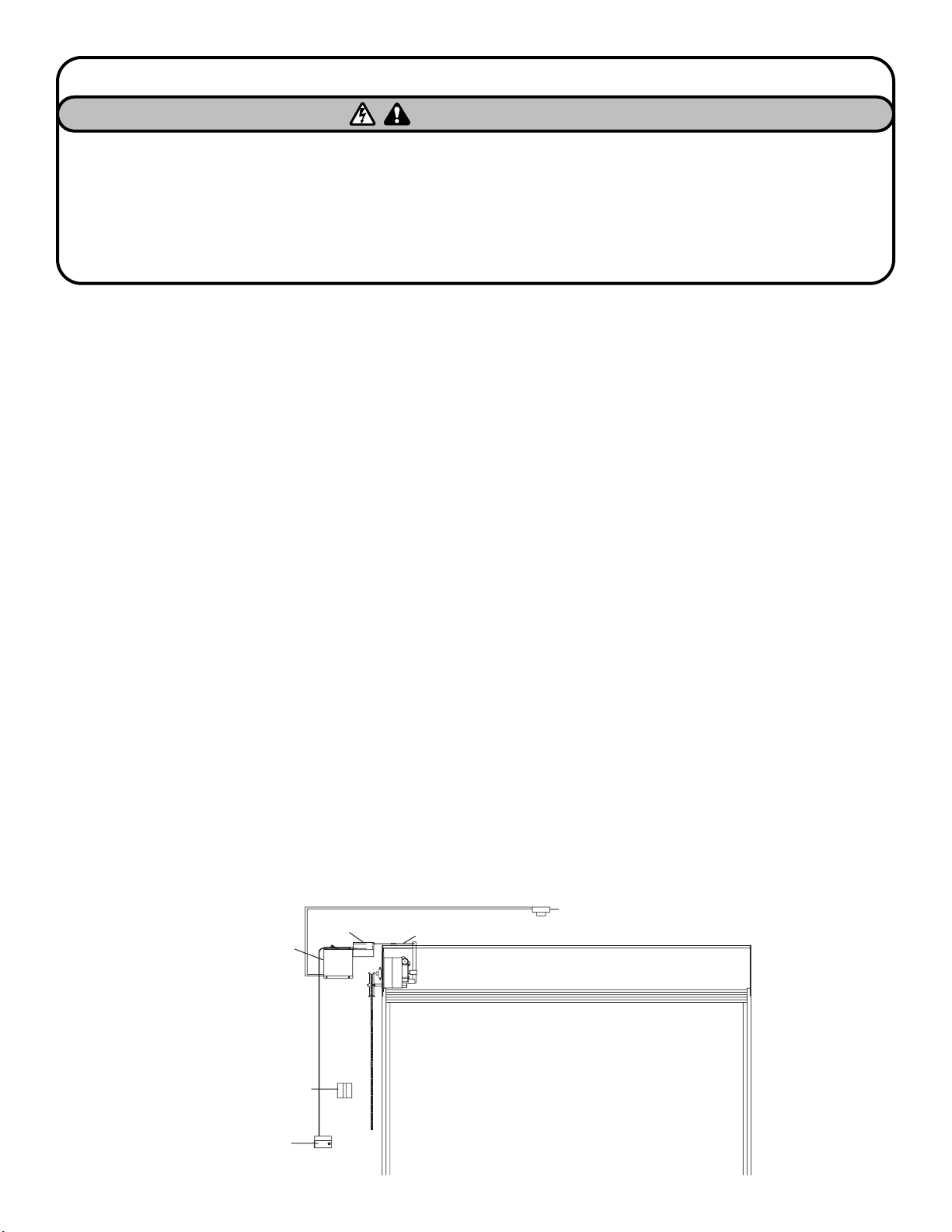
TYPICAL INSTALLATION
Releasing Device
with Reset Mechanism
End Link
Smoke Detector
Fuse Link, Sash Chain or Cable
Grifco Fire Door Hoist
Optional Signal Appliance
Tamper Resistant
Reset Handle
FIGURE 1
IMPORTANT INSTALLATION INSTRUCTIONS
To reduce the risk of SEVERE INJURY or DEATH:
WARNING
WARNING
WARNING
1. READ AND FOLLOW ALL INSTALLATION WARNINGS AND
INSTRUCTIONS.
2. NEVER connect release device to power source until
instructed to do so.
3. DO NOT install this device on a motorized door without an
electric safety edge.
4. DO NOT use this device without fuse links installed.
5. Concrete anchors MUST be used if mounting release device
into masonry.
6. DO NOT exceed maximum pull rating of 40 lbs. on
releasing device.
Page 3

RELEASING DEVICE TEST / RESET PROCEDURES
NOTE: To be performed by factory authorized personnel only.
Regular testing of all release device equipment is recommended.
Testing shall be witnessed for proper operation.
The following test/reset procedure applies to all release devices
using the reset mechanism. These procedures are supplemental to
test procedures provided in the release device manual. Testing
affects normal operation of central alarm system when connected
to release device. Testing and normal operation can only be
accomplished with power applied to unit. When power is applied
to unit under test, the “Power” LED (red) will be lit on the release
device.
NOTE: Clear fire door opening and prohibit all traffic through
opening while testing the system.
Door must be in open position with power applied to unit to
begin testing.
1. Depress and continue to hold test button on side of release
device (Figure 1). After factory adjusted 10 second alarm
verification (10 sec. delay) device will release door (Figure 3a).
Release test button.
2. Reset and release device by pulling reset cable in a downward
until end link fully engages release device (Figure 3b). Push
reset cable inward until handle rests against jam nut or set
position (Figure 3c).
3. Using a chain hoist, raise door to fully open position.
4. Follow steps 2 and 3 for resetting of release device. See the
release device manual for complete release device test
procedures.
After completing tests, make sure door is in normally open
position and all power required for normal operation is restored.
NOTE: Testing of release devices is independent of, and shall in
no way be interpreted as an alternative method of, testing fire
alarm systems, motorized operator and/or any other system
component employed on the fire door or counter fire door
installation.
FIGURE 3a
FIGURE 2
FIGURE 3b
FIGURE 3c
9" minimum
bend radius
SS90 A/B
7.5x8 x4
(H x w x D)
Wire Stop:
1" maximum
from cable end
See door manufacturer
instructions and NFPA 80
for proper cable and
fusible link configuration.
3/16" conduit clip
or conduit clamp
Page 4

01-30632 © 2006, The Chamberlain Group, Inc.
Issue Date 8/18/2006 All Rights Reserved
WARRANTY SERVICE PROCEDURE
Contact technical support at the number provided below for assistance in determining possible product failure. Installer shall provide
the following information when contacting technical support:
• Serial Number, found in the following locations
• Individual unit shipping box
• Cover of installation manual
• On unit
• Name of Distributor who supplied product
• Name of End User and/or installation company if different from Distributor
• Detailed description of product non conformity
To receive a Return Goods Authorization (RGA) and shipping address for a product believed to be defective, all of the above information
shall be required. Products returned without a valid RGA shall be refused receipt. If provided, reference troubleshooting guide that
accompanies product prior to requesting an RGA.
Contact Information
Technical Support: 1-800-929-2553
 Loading...