

Page 1
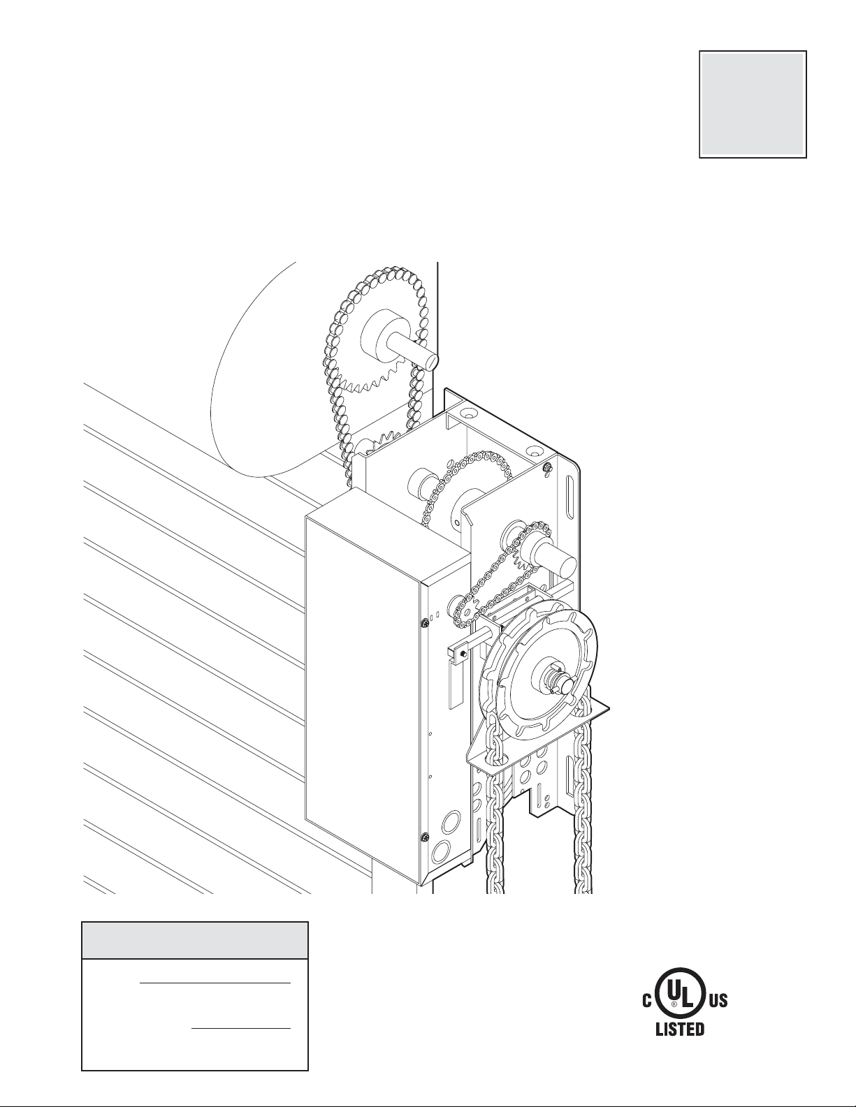
OWNER'S MANUAL
MODELS:
MJ
✦
MH
✦
HMJ
INDUSTRIAL DUTY DOOR OPERATOR
NOT FOR RESIDENTIAL USE
Serial #
(located on electrical box cover)
Installation Date
Wiring Type
2 YEAR WARRANTY
41B6
FACTORY SET
C2 Wiring
See page 8 for
other wiring
configurations
Page 2

2
SAFETY
DISCONNECT :
Model MJ: Floor level disconnect for emergency
manual door operation.
Model MH: Floor level chain hoist with electrical interlock
for emergency manual door operation.
Model HMJ: Includes both floor level disconnect systems
described above.
REVERSING EDGE:...............(Optional) Electric or
pneumatic sensing device attached to the bottom edge
of door.
A REVERSING EDGE IS STRONGLY RECOMMENDED
FOR ALL COMMERCIAL OPERATOR
INSTALLATIONS. REQUIRED WHEN THE 3 BUTTON
CONTROL STATION IS OUT OF SIGHT OF DOOR OR
ANY OTHER CONTROL (AUTOMATIC OR MANUAL)
IS USED.
SPECIFICATIONS
ELECTRICAL
TRANSFORMER:.............24Vac
CONTROL STATION: ......NEMA 1 3-button station.
OPEN/CLOSE/STOP
WIRING TYPE:.................C2 (Standard)
Momentary contact to OPEN & STOP, constant
pressure to CLOSE, open override plus wiring for
sensing device to reverse. See pages 13 and 14 for
optional control settings and operating modes.
LIMIT ADJUST: ................Linear driven, fully
adjustable screw type cams. Adjustable to 24 feet.
WEIGHTS AND DIMENSIONS
HANGING WEIGHT: .........80-110 LBS.
MOTOR
TYPE: .................................Intermittent duty
HORSEPOWER: ................1/2 HP
SPEED:...............................1000 RPM
VOLTAGE: ..........................115V 1 Phase 60Hz,
230V 1 Phase 50Hz
CURRENT:..........................See motor nameplate
MECHANICAL
DRIVE REDUCTION:.............Primary: Heavy duty
(4L) V-Belt. Secondary: #48 chain/sprocket. Output:
#48 chain
OUTPUT SHAFT SPEED:.....80 RPM
DOOR SPEED: ......................approx. 9" per sec.
depending on door
BRAKE (Optional): ...............Solenoid actuated disc
brake
BEARINGS: ...........................IronCopper sintered and
oil impregnated.
HAND CHAIN WHEEL: .........Left or right handing
Models MH and HMJ
only.
12.69"
6.34"
10.88"
6.34"
7.00"
15.78"
6.13"
9.19"
3.63"
2.91"
18.50"
Hand Chain Wheel
present with Model
MH only.
MOUNTING DIMENSIONS
A - Wall Mounting
B - Bracket Mounting (rolling door)
A
A
14.75"
A
A
7.00"
Page 3
3
PREPARATION
It is imperative that the wall or mounting surface
provide adequate support for the operator.
This surface must:
a. Be rigid to prevent play between operator and
door shaft.
b. Provide a level base.
c. Permit the operator to be fastened securely and
with the drive shaft parallel to the door shaft.
The safety and wear of the operator will be adversely
affected if any of the above requirements are not met.
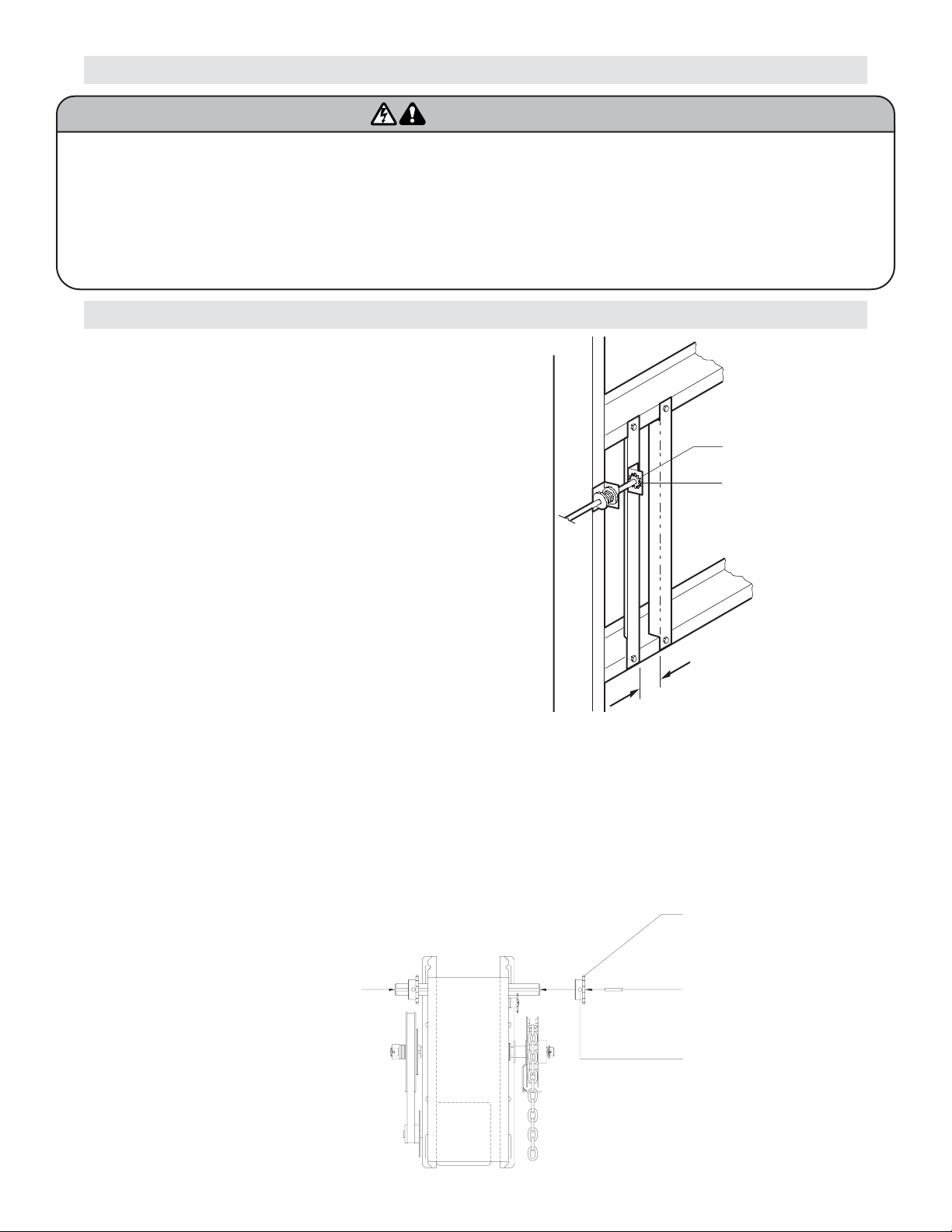
For metal buildings, fasten 2" x 2" x 3/16" (or larger)
angle iron frames to the building purlins. Retain
5-1/2" between frames (Figure 1).
All MJ, MH, and HMJ series operators have dual output shafts and may be mounted on either the right (standard)
or left side of door, and in either a vertical (standard) or horizontal mounting position. If you need to move the drive
sprocket, loosen BOTH set screws, remove the sprocket and key, and place on the opposite side of the drive shaft.
Be sure to tighten BOTH set screws securely
Hand Chain Handing
For MH and HMJ models with manual hoist hand chain systems, the handing of the operator must be determined
at the time of order. The handing is indicated by last letter of the model name (R or L). The hand chain wheel
can not be switched on site. If your installation causes the hand chain to hang in the door opening, hook the
chain off to the side near the top of the door jamb.
IMPORTANT SAFETY NOTES
To prevent possible SERIOUS INJURY or DEATH:
• DO NOT connect electric power until instructed to do so.
• If the door lock needs to remain functional, install an interlock
switch.
• ALWAYS call a trained professional door serviceman if door
binds, sticks or is out of balance. An unbalanced door may not
reverse when required.
• NEVER try to loosen, move or adjust doors, door springs,
cables, pulleys, brackets or their hardware, ALL of which are
under EXTREME tension and can cause SERIOUS PERSONAL
INJURY.
• Disable ALL locks and remove ALL ropes connected to door
BEFORE installing and operating door operator to avoid
entanglement.
WARNING
WARNING
Shaft Support Bracket
with Bearing (Not Provided)
Door Sprocket
5-1/2" (13.97 cm)
(2) Set Screws
Output Shaft
Key
Drive Sprocket
Page 4
4
OPTIONAL
Mounting Bracket
P/N 08-9098
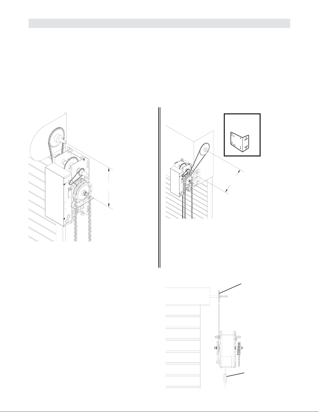
1b. Bracket or Shelf Mounting
The operator may be mounted either above or
below the door shaft. The optimum distance
between the door shaft and operator drive shaft is
between 12" - 15" (Figure 4).
1a. Wall Mounting
The operator should generally be installed below
the door shaft, and as close to the door as
possible. The optimum distance between the door
shaft and operator drive shaft is between 12" - 15"
(Figure 3).
INSTALLATION
IMPORTANT: The shelf or bracket must
provide adequate support, prevent play
between operator and door shaft, and permit
operator to be fastened securely and with the
drive shaft parallel to the door shaft.
1c. Place door sprocket on the door shaft. Do not
insert the key at this time.
2. Place drive sprocket on the appropriate side of the
operator. Do not insert the key at this time.
3. Wrap drive chain around door sprocket and join
roller chain ends together with master link.
4. Raise operator to approximate mounting position
and position chain over operator sprocket.
5. Raise or lower operator until the chain is taut (not
tight). Make sure the operator output shaft is
parallel to door shaft and sprockets are aligned.
When in position, secure the operator to wall or
mounting bracket.
6. Align sprockets and secure (Figure 5).
FIGURE 4
FIGURE 3
Important NOTE: Before your operator is installed, be sure the door has been properly aligned and is working
smoothly. The operator may be wall mounted or mounted on a bracket or shelf. If necessary, refer to the operator
preparations on page 3. Refer to the illustration and instructions below that suits your application.
FIGURE 5
Optimum Distance
12 - 15"
OPTIONAL
Mounting Bracket
P/N 10-9095
Optimum Distance
12 - 15"
Typical Right Hand
Wall Mounted Operator
Be sure door
sprocket is properly
aligned with drive
before securing to
the shaft.
Chain Retaining
Bracket
Page 5
5
Keyhole Bracket
These operators are equipped with a manual hoist. An
electrical interlock will disable the electrical controls
when the hoist is used. To operate the hoist:
1. Pull the disconnect chain (small chain) to engage
the hoist mechanism. The disconnect chain may be
locked in position by slipping the end through the
keyhole of the chain keeper mounted on the wall.
2. Operate the door in the desired direction by pulling
on one side or the other of the continuous loop hoist
chain (large chain).
3. The disconnect chain must be released from the
chain keeper before the door will operate again
electrically.
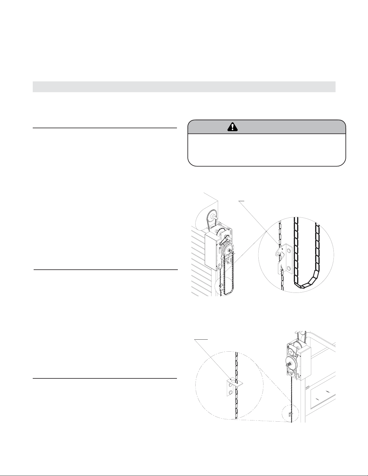
7. Install Hand Chain (Models MH and HMJ only)
Place hand chain around hand chain wheel. Be
sure to pass it through both openings in the chain
guide. Remove enough links so chain hangs
approximately two feet above the floor
MANUAL OPERATION
This operator has provisions for manually operating the door in case of emergency or power failure. Refer to the
appropriate instructions below for your model operator.
Model MH
Model MJ
This operator has a floor level disconnect chain to
disconnect the door from the door operator.
1. To disengage, pull the chain and secure in the
disengaged position by slipping the end through the
keyhole bracket mounted on the wall. Or if emergency
egress device is used, pull handle to disengage
operator from door.
2. The door may now be pushed up or pulled down
manually. Release the disconnect chain to operate the
door again electrically.
8. Mount Chain Keeper / Keyhole Bracket
Using suitable hardware mount the chain keeper
approximately 4 feet above the floor, near the free
hanging chain. Remove disconnect sash chain
from bag and place the end through the keyhole in
the the chain keeper. Remove excess links if
necessary.
Manual Disconnect for Models MJ and HMJ
Electrical Interlock with Hoist for Models MH and HMJ
Chain Retaining Bracket
(with pad locking provisions)
Model HMJ
This operator includes both a floor level disconnect
chain to disconnect the door from the door operator
and a disconnect chain with manual hoist to electrically
disable the operator controls.
1. Refer to Model MH instructions above for hoist
operation.
2. Refer to Model MJ instructions above for manual
operation.
To prevent possible SERIOUS INJURY from a moving chain,
DISCONNECT electric power to the operator BEFORE manually
operating your door.
WARNING
WARNING
Page 6
6
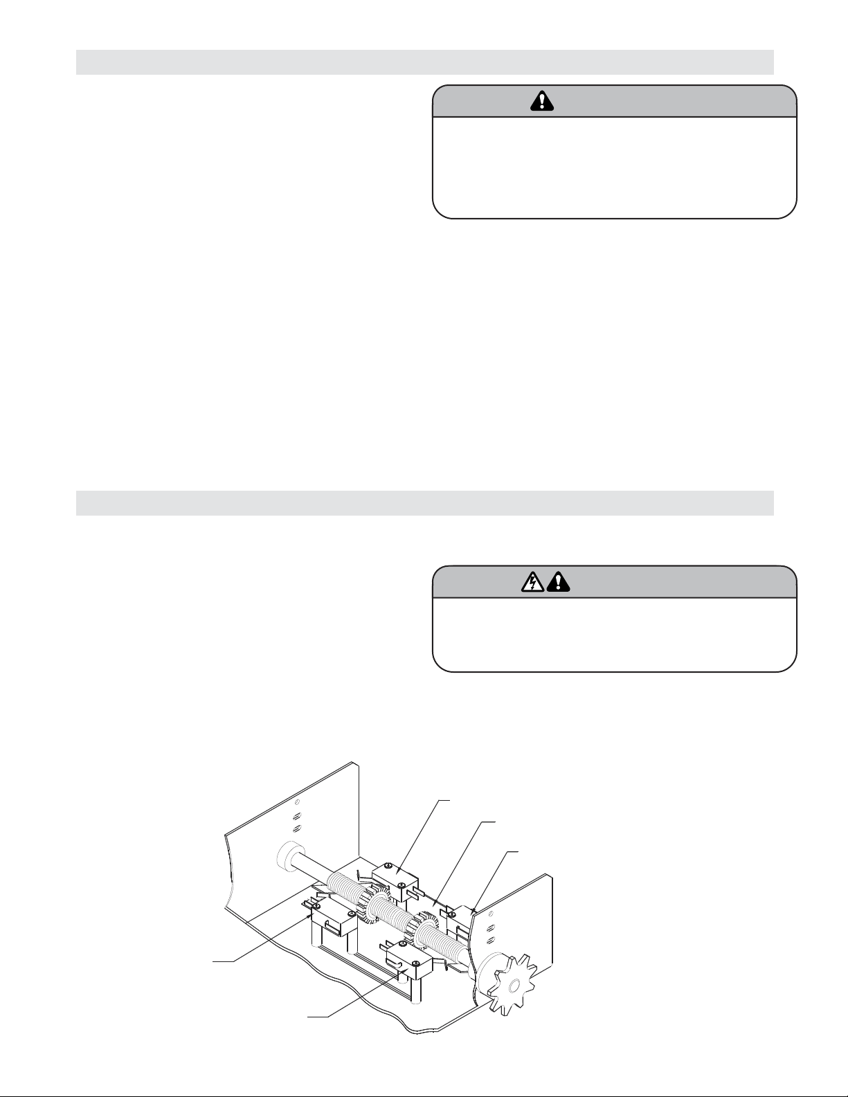
LIMIT SWITCH ADJUSTMENT
NOTE: Make sure the limit nuts are positioned between the limit switch actuators before proceeding with
adjustments.
If other problems persist, call our toll-free number for
assistance - 1-800-528-2806.
1. To adjust limit nuts depress retaining plate to allow
nut to spin freely. After adjustment, release plate
and ensure it seats fully in slots of both nuts.
2. To increase door travel, spin nut away from
actuator. To decrease door travel, spin limit nut
toward actuator.
3. Adjust open limit nut so that door will stop in open
position with the bottom of the door even with top
of door opening.
4. Repeat Steps 1 and 2 for close cycle. Adjust close
limit nut so that actuator is engaged as door fully
seats at the floor.
SENSING EDGES
All types of sensing edges with an isolated normally
open (N.O.) output are compatible with your operator.
This includes pneumatic and electric edges. If your
door does not have a bottom sensing edge and you
wish to purchase one, contact the supplier of your
operator.
If not pre-installed by the door manufacturer, mount
the sensing edge on the door according to the
instructions provided with the edge. The sensing
edge may be electrically connected by either coiled
cord or take-up reel. Refer to the steps below.
Important Notes:
a. Proceed with Limit Switch Adjustments before
making any sensing edge wiring connections to
operator as described below.
b. Electrician must hardwire the junction box to the
operator electrical box in accordance with local
codes.
ENTRAPMENT PROTECTION ACCESSORIES (OPTIONAL)
WIRING:
For wiring of your sensing device to the operator, refer
to the wiring diagram supplied with your operator.
See field connection terminals identified as Sensing
Device or Safety Edge.
TAKE-UP REEL: Take-up reel should be installed 12"
above the top of the door.
COIL CORD: Connect operator end of coil cord to
junction box (not supplied) fastened to the wall
approximately halfway up the door opening.
To reduce the risk of SEVERE INJURY or DEATH, ALWAYS
install reversing sensors when the 3-button control station is
out of sight of door or ANY other control (automatic or manual)
is used. Reversing devices are recommended for ALL
installations.
WARNING
WARNING
To avoid SERIOUS PERSONAL INJURY or DEATH from
electrocution, disconnect electric power BEFORE manually
moving limit nuts.
WARNING
WARNING
OPEN Limit Switch
Retaining Plate
CLOSE Limit Switch
Aux. OPEN
Limit Switch
SAFETY
(Aux. Close) Limit Switch
Page 7
To reduce the risk of SEVERE INJURY or DEATH:
• ANY maintenance to the operator or in the area near the
operator MUST NOT be performed until disconnecting the
electrical power and locking-out the power via the operator
power switch. Upon completion of maintenance the area
MUST be cleared and secured, at that time the unit may be
returned to service.
• Disconnect power at the fuse box BEFORE proceeding.
Operator MUST be properly grounded and connected in
accordance with local electrical codes. The operator should
be on a separate fused line of adequate capacity.
• All electrical connections MUST be made by a qualified
individual.
• DO NOT install ANY wiring or attempt to run the operator
without consulting the wiring diagram. We recommend that
you install an optional reversing edge BEFORE proceeding
with the control station installation.
• ALL power wiring should be on a dedicated circuit and well
protected. The location of the power disconnect should be
visible and clearly labeled.
• ALL power and control wiring must be run in separate
conduit.
• To avoid damage to door and operator, make ALL door locks
inoperative. Secure locks(s) in “OPEN” position. If the door
lock needs to remain functional, install an interlock switch.
WARNING
WARNING
7
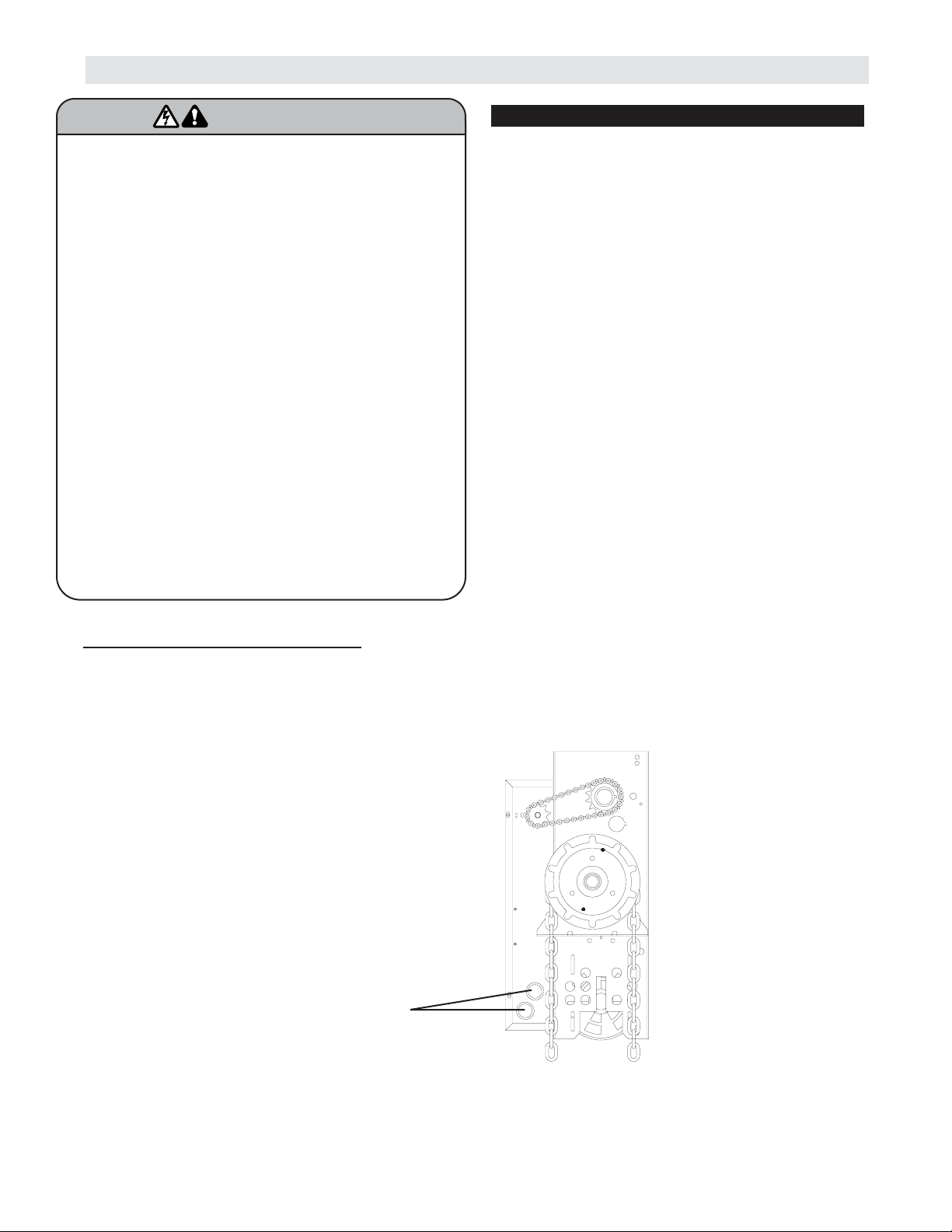
POWER WIRING
ON THREE PHASE MACHINES ONLY!
Incorrect phasing of the power supply will cause the motor to rotate in the wrong direction (open when CLOSE
button is pressed and vice-versa). To change motor rotation, exchange incoming power leads L1 and L2.
CONDUIT ACCESS
1. Remove the cover from the electrical enclosure.
Inside this enclosure you will find the wiring diagram(s)
for your unit. Refer to the diagram (glued on the inside
of the cover) for all connections described below. If this
diagram is missing, call the number on the back of this
manual. DO NOT INSTALL ANY WIRING OR
ATTEMPT TO RUN THIS OPERATOR WITHOUT
CONSULTING THE WIRING DIAGRAM.
2. Be sure that the power supply is of the correct
voltage, phase, frequency, and amperage to supply
the operator. Refer to the operator nameplate on the
cover.
3. Using the 1-1/16" dia conduit access hole as
shown below, bring supply lines to the operator and
connect wires to the terminals indicated on the
WIRING CONNECTIONS DIAGRAM.
4. Important NOTE: Connect earth ground to the
chassis ground screw in the electrical box enclosure.
Do not turn power on until you have finished making all
power and control wiring connections and have
completed the limit switch adjustment procedure.
POWER WIRING CONNECTIONS
Three (3) 7/8" & 1-1/6" DIA. Knockouts
for Power & Control Wiring access
(Near & Opposite side)
Page 8

WIRING
This Operator has
Control Wiring.
SUPPLEMENTAL WIRING DIAGRAM(S)
REPLACEMENT WIRING DIAGRAM
Note: Supplemental Wiring Diagrams are
to be used in addition to 1753 or 1754.
Replacement Wiring Diagram is to be used
in place of 1753 or 1754.
SPECIAL CONTROL
WIRING DATA
Wiring
Type
O
PEN
ESO
LC
8
CONTROL WIRING
LOCATING THE CONTROL STATION
All operators are supplied with some type of control station. Generally a three button station
(OPEN/CLOSE/STOP) is provided. A two-position key switch or control station (OPEN/CLOSE) may be added or
substituted when requested at the time of order. Mount the control station near the door.
IMPORTANT: Mount WARNING NOTICE beside or
below the push button station.
MOUNT WARNING NOTICE
Standard C2 or B2 Wiring
Standard operators are shipped from the factory with
jumper set for C2 wiring, which requires constant
pressure on button to close the door. If momentary
contact on close direction is desired (B2 wiring) you
must include an entrapment protection device. See
close control settings to the right.
Constant pressure on close (C2 wiring)
In the electrical enclosure, a RED wire was placed on
terminal block #12. With this setting, the operator will
require constant pressure on close control in order to
keep door moving in the close direction.
Wiring Diagram label on inside cover
of electrical box
SPECIAL CONTROL WIRING
If your operator was shipped from the factory with
non-standard control wiring or with optional
accessories that require addition instructions, refer to
the wiring diagram(s) indicated in the special control
wiring data box. When a replacement wiring diagram
is present, wiring diagrams in this manual will not
apply. Refer only to the replacement wiring diagram
for all connections.
To prevent possible SERIOUS INJURY or DEATH, install
reversing sensors when the 3-button control station is out of
sight of the door or ANY other control (automatic or manual) is
used. Reversing devices are recommended for ALL
installations.
WARNING
WARNING
DETERMINE WIRING TYPE
Refer to the wiring diagram located on the inside cover the electrical box to determine the type of control wiring.
Momentary contact on close (B2 wiring)
Move RED wire from terminal block #12 to terminal #2.
The operator will require only momentary contact to
close the door.
Control Station
O
PEN
Push
Buttons
C
OL
ES
S
TOP
W A R N I N G
TO PREVENT ENTRAPMENT
DO NOT START DOOR DOWNWARD
UNLESS DOORWAY IS CLEAR
WARNING Notice
Page 9

9
CONTROL WIRING (cont’d)
Radio Controls
On all models with type C2 control wiring, a terminal
bracket marked R1 R2 R3 is located on the outside of
the electrical enclosure. All standard radio receivers
(single channel residential type) may be mounted to this
bracket. The operator will then open a fully closed door, close a fully open door, and reverse a closing door from
the radio transmitter. However, for complete door control from a remote, a commercial three-channel radio receiver
(with connections for OPEN/CLOSE/STOP) is recommended.
Additional Access Control Equipment
Locate any additional access control equipment as desired (but so that the door will be in clear sight of the person
operating the equipment), and connect to the terminal block in the electrical enclosure as shown on the FIELD
WIRING CONNECTIONS diagram. Any control with a normally (N.O.) isolated output contact may be connected
in parallel with the OPEN button. More than one device may be connected in this manner. Use 16 gauge wire or
larger for all controls. DO NOT USE THE CONTROL CIRCUIT TRANSFORMER (24VAC) IN THE OPERATOR TO
POWER ANY ACCESS CONTROL EQUIPMENT OTHER THAN A STANDARD RESIDENTIAL TYPE RADIO
RECEIVER.
External Interlock Switch
The operator has a terminal connection for an external interlock switch. This switch must be a normally closed
(N.C.) two-wire device with a contact rating of at least 3 amps @ 24VAC. When such a switch is connected as
shown on the FIELD WIRING CONNECTIONS diagram, the control circuit will be disabled when the switch is
actuated, thereby preventing electrical operation of the door from the control devices.
CLUTCH ADJUSTMENT
1. Remove cotterpin from nut on the clutch shaft.
2. Back off clutch nut until there is very little tension
on the clutch spring.
3. Tighten clutch nut gradually until there is just
enough tension to permit the operator to move the
door smoothly but to allow the clutch to slip if the
door is obstructed. When the clutch is properly
adjusted, it should generally be possible to stop
the door by hand during travel.
4. Reinstall cotterpin.
NOTE: The adjustable friction clutch is NOT an
automatic reversing device. An electric or
pneumatic reversing edge can be added to bottom
edge of door if desired.
To prevent possible SERIOUS INJURY or DEATH, install
reversing sensors when the 3-button control station is out of
sight of the door or any other control (automatic or manual) is
used. Reversing devices are recommended for ALL
installations.
WARNING
WARNING
To prevent possible SERIOUS INJURY or DEATH from a moving
gate or garage door:
• ALWAYS keep remote controls out of reach of children.
NEVER permit children to operate, or play with remote
controls.
• Activate gate or door ONLY when it can be seen clearly, is
properly adjusted, and there are no obstructions to door
travel.
• ALWAYS keep gate or garage door in sight until completely
closed. NEVER permit anyone to cross path of moving gate
or door.
WARNING
WARNING
Install the control station and receiver where the door is
visible, but away from the door and its hardware. When a
receiver is used to activate a commercial door opener, a
reversing edge MUST be installed on the bottom of the door.
Failure to install a reversing edge under these circumstances
may result in SERIOUS INJURY or DEATH to persons trapped
beneath the door.
WARNING
WARNING
Adjusting Nut
Spring
Cotterpin
Washer
Clutch Pulley
Clutch Pad
Clutch Plate
Page 10

10
TEST THE SYSTEM
Turn on power. Test all controls and safety devices to
make sure they are working properly. It will be
necessary to refer back to page 6 for fine adjustment
of the limit switches.
IMPORTANT NOTES:
• Do not leave operator power on unless all safety
and entrapment protection devices have been
tested and are working properly.
• Be sure you have read and understand all Safety
Instructions included in this manual.
• Be sure the owner or person(s) responsible for
operation of the door have read and understand
the Safety Instructions, know how to electrically
operate the door in a safe manner, and know how
to use the manual disconnect operation of the door
operating system.
ADJUSTMENT
A solenoid brake is an optional modification. If present, the brake is adjusted at the factory and should not need
additional adjustment for the the life of the friction pad. If desired, a brake can also be field installed. To order a
kit for field installation on an existing operator, call the parts and service department at 1-800-528-2806.
Replace friction pads when necessary. Refer to the
illustration for identification of components for the
solenoid type brake system.
Solenoid Brake System
To reduce the risk of SEVERE INJURY or DEATH:
• ANY maintenance to the operator or in the area near the
operator MUST NOT be performed until disconnecting the
electrical power and locking-out the power via the operator
power switch. Upon completion of maintenance the area
MUST be cleared and secured, at that time the unit may be
returned to service.
• Disconnect power at the fuse box BEFORE proceeding.
Operator MUST be properly grounded and connected in
accordance with local electrical codes. The operator should
be on a separate fused line of adequate capacity.
• All electrical connections MUST be made by a qualified
individual.
• DO NOT install ANY wiring or attempt to run the operator
without consulting the wiring diagram. We recommend that
you install an optional reversing edge BEFORE proceeding
with the control station installation.
• ALL power wiring should be on a dedicated circuit and well
protected. The location of the power disconnect should be
visible and clearly labeled.
• ALL power and control wiring MUST be run in separate
conduit.
WARNING
WARNING
Solenoid
Release Lever
Friction Pad
Pulley
Page 11

11
✳ Use SAE 30 Oil (Never use grease or
silicone spray).
✔ Repeat ALL procedures.
■ Do not lubricate motor. Motor bearings are
rated for continuous operation.
■ Do not lubricate clutch or V-belt.
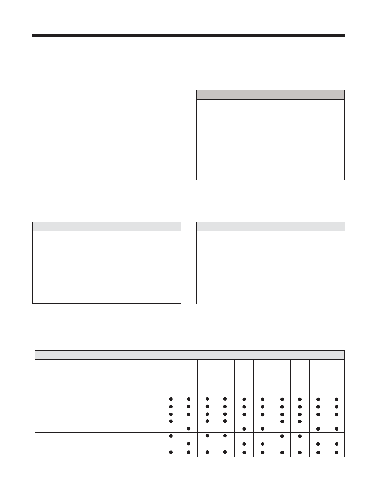
■ Inspect and service whenever a malfunction is observed or suspected.
Check at the intervals listed in the following chart.
HOW TO ORDER REPAIR PARTS
OUR LARGE SERVICE ORGANIZATION SPANS AMERICA
Installation and service information is available
CALL OUR TOLL FREE number:
1-800-528-2806
WHEN ORDERING REPAIR PARTS
PLEASE SUPPLY THE FOLLOWING INFORMATION:
PART NUMBER DESCRIPTION MODEL NUMBER
ADDRESS ORDER TO:
THE CHAMBERLAIN GROUP, INC.
Technical Support Center
6020 S. Country Club
Tucson, AZ 85706
EVERY EVERY EVERY
ITEM PROCEDURE 3 MONTHS 6 MONTHS 12 MONTHS
Drive Chain Check for excessive slack.
Check & adjust as required.
Lubricate.*
●✔
Sprockets Check set screw tightness ●✔
Clutch Check & adjust as required ●✔
Belt Check condition & tension ●✔
Fasteners Check & tighten as required ●✔
Manual Disconnect Check & Operate ●✔
Bearings & Shafts Check for wear & lubricate ●✔
MAINTENANCE SCHEDULE
To avoid SERIOUS PERSONAL INJURY or DEATH from
electrocution, disconnect ALL electric power BEFORE
performing ANY maintenance.
WARNING
WARNING
Page 12

12
SCHEMATIC DIAGRAM
1754
(OPTIONAL)
BIMETAL
RELAY
C
BL
RES.
CAPACITOR
B
A
Y
W
MOTOR *
BK
O/L
Y
R
L1
BR
L2
BK
BK
(OPTIONAL)
LIGHT
MAX.
100W
BK
W
OPEN-A
R
W
CLOSE-B
C
N.O.
CLOSE-C
OPEN-C
STOP
3
MOVE JUMPER WIRE TO TERMINAL #2
FOR MOMENTARY CONTACT ON CLOSE
4
BRAKE SOLENOID
(WHEN PRESENT)
Y
HAND CHAIN
INTERLOCK SW.
BL/BK
R
PR1.
24VAC.
SEC.
10VA.
Y
WIRE NUT
W
R3
12
BL
C
OR
P
BR
R1
OPEN
SAFETY
EDGE
W
PULL SWITCH
TO
10
GY
GY
A.R.S. BOARD
(When Present)
34
OPEN & CLOSE
7
CLOSE
BR
AUX.
CLOSE L/S
215
R2
Y
Y
R
OR
GY
BL
OPEN-B
1
OR
AUX.
OPEN
L/S
P
2
* TO REVERSE MOTOR ROTATION INTERCHANGE
RED AND YELLOW MOTOR WIRES.
CLOSE-A
N.O.
OP
Y
CL
R
OPEN L.S.
OR
N.C.
CLOSE L/S
P
N.C.
W
11
C
W
W
C
Page 13

13
WIRING DIAGRAM
1754
W
CAPACITOR
W
PRIMARY
XFMR
SECONDARY
Y
**
INTLK.
COM
5
4
3
2
1
A.R.S. BOARD
(When Present)
RESISTOR
Y
R
R
BK
Y
Y
N.O.
Y
GY
OR
P
1234
OPEN
CLOSE
STOP
SAFETY EDGE
BR
GY
P
N.C.
OR
AUX.CLOSE
N.C.
W
R3
Y
R2
R1
BR
CLOSE
RADIO
REC'R
COM
COM
GY
W
COM
Y
OPEN
AUX.OPEN
OR
N.C.
P
N.O.
TO REVERSE MOTOR DIRECTION
INTERCHANGE RED & YELLOW WIRES.
MOTOR
Y
O/L
R
BK
BL
R
BA
NC
BL
NO
OR
C
BR
BR
WIRE NUT
W
C
NC
NO
W
C
OP
BL/BK
R
BK
BL
1210711
BK
L2L1
GROUND
W
GYY
Y
BRAKE
SOLENOID
BL/BK
BL/BK
BA
C
NC
NC
NO
NO
C
C
CL
P
P
OR
BL R
See Close Control
Wiring Options Below
RATED LINE
VOLTAGE
PULL SWITCH TO
OPEN & CLOSE
CLOSE CONTROL WIRING OPTIONS
C2 WIRING - Constant Presssure to Close
*
RED WIRE ON TERMINAL #12 (Shipped from Factory)
B2 WIRING - Momentary Contact to Close
MOVE RED WIRE FROM TERMINAL #12 TO TERMINAL #2
- INTERLOCK SWITCH (WHEN SUPPLIED)
**
WIRED N.O. HELD CLOSED.
- Shipped from Factory
*
Page 14
14
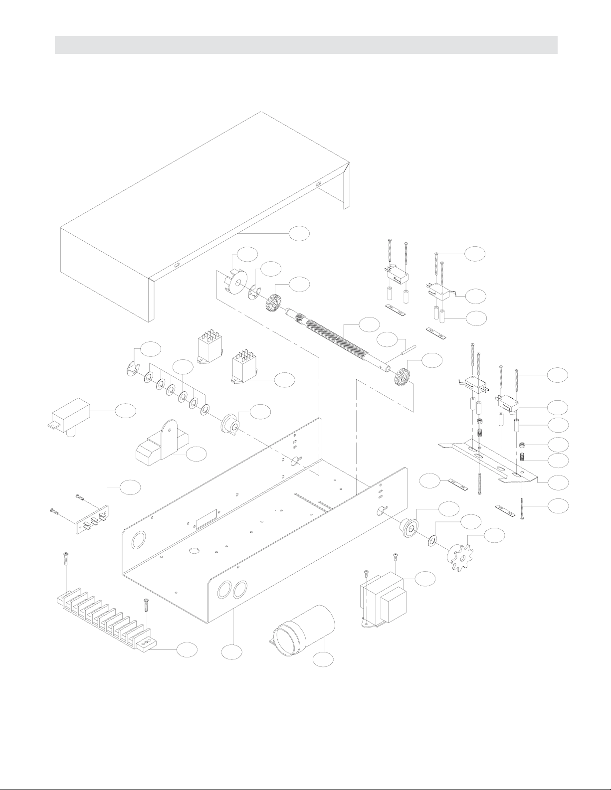
ELECTRICAL BOX - ILLUSTRATED PARTS
2
L2
S5
S3
S4
S5
S3
S4
S8
S2
S1
S6
L6
L4
L5
L8
L3
L1
L8
L6
8
3
6
4
L2
L7
L3
S7
7
5
1
9
Page 15
15
REPLACEMENT PART KITS
Below are replacement kits available for your operator. For replacement of electrical box, motor or brake
components be sure to match model number of your unit to kit number below to ensure proper voltage
requirements. Optional modifications and/or accessories included with your operator may add or remove certain
components from these lists. Please consult a parts and service representative regarding availability of individual
components of kits specified below. Refer to page 11 for all repair part ordering information.
Complete Electrical Box Service Kits
K-MJ5011 Model MJ5011, 115V
K-MJ5025 Model MJ5025, 230V
K-MH5011R Model MH5011R, 115V RH
K-MH5011L Model MH5011L, 115V LH
K-MH5025R Model MH5025R, 230V RH
K-MH5025L Model MH5025L, 230V LH
K-HMJ5011R Model HMJ5011R, 115V RH
K-HMJ5011L Model HMJ5011L, 115V LH
K-HMJ5025R Model HMJ5025R, 230V RH
K-HMJ5025L Model HMJ5025L, 230V LH
VARIABLE COMPONENT KITS
PART NUMBER
K13-10024
K23-10041
K29-2
K21-10340
K21-5230
K29-10338
K29-12110
K24-24-6
DESCRIPTION
Limit Nut, (set of 2)
Limit Switch
Resistor, 2 Ohm
Transformer, 115V
Transformer, 230V
Capacitor, 70MFD
Capacitor, 20MFD
Relay, 3PDT
MJ5011
MJ5025
MH5011R
MH5011L
MH5025R
MH5025L
HMJ5011R
HMJ5011L
HMJ5025R
HMJ5025L
* Electrical Box Kits include parts from K72-12487 and K75-12493
1
2
3
4
5
6
7
8
9
10-10315
10-10316
23-10916
42-10040
42-110
29-2
(See Var. Comp.)
(See Var. Comp.)
(See Var. Comp.)
MT Electrical Box
MT Electrical Box Cover
SPDT Interlock Switch
Terminal Assembly 3 Lug
10 Position Terminal Block
Resistor, 2ohm
Transformer
Relay, 24V
Motor Capacitor
1
1
1
1
1
1
1
2
1
* COMPLETE ELECTRICAL BOX KITS
K72-12487 LIMIT SHAFT ASSEMBLY KIT
Item
L1
L2
L3
L4
L5
L6
L7
L8
Description
MT Limit Shaft
Flange Bearing 3/8" I.D.
Limit Nut
Sprocket 48B9 x 3/8" Powder Metal
RPM Rotating Cup
Washer, Shim 3/8" I.D. x .010 THK.
Rollpin 1/8 x 1" Long
E Ring, 3/8"
Qty
1
2
2
1
1
7
1
2
K75-12493 LIMIT SWITCH ASSEMBLY KIT
P/N
11-10321
12-10028
13-10024
15-48B9A1
29-10344
80-10026
86-RP04-100
87-E-075
Item
S1
S2
S3
S4
S5
S6
S7
S8
Description
Depress Plate
Spring, Depress Plate
Limit Switch
Standoff, Limit Switch
Screw, #4-40 x 1-3/8" Pan Hd Phil
Screw, #6-32 x 1" Pan Hd Phil
Nut, Double Tinnerman
Locknut, #6-32 Nylon Hex
Qty
1
2
4
8
8
2
4
2
P/N
10-10318
18-10036
23-10041
31-10043
82-PX0419
82-PX0616
84-DT-04
84-LN-06
Page 16

16
ILLUSTRATED PARTS – Model MJ
D6
D2
D7
D5
D9
D8
D3
O12
O4
O10
O6
C12
C8
C11
C7
D1
O5
O9
O1
O2
D4
1
4
3
C2
C9
O7
C15
C1
C4
2
1
C10
B11
B1
B2
C6
B8
B10
B5
B9
O8
O3
O10
C15
C4
O2
C15
C3
C15
C5
C13
C14
B6
B3
5
B2
B12
B7
B4
Page 17

17
REPAIR PARTS LIST – MODEL MJ
ITEM PART# DESCRIPTION
J1 10-10707 Disconnect Support Bracket
J2 10-10708 Yoke
J3 10-10709 Disconnect Lever
J4 11-10710 Disconnect Shaft
J5 18-10178 Tension Spring
J6 19-8A-12 Sash Chain, 12'
J7 86-CP04-112 Cotter Pin 1/8x1-3/4" ZP
J8 86-CP05-108 Cotter Pin 5/32x1-1/2"
J9 86-RP04-100 Roll Pin 1/8x1"
INDIVIDUAL PARTS
K75-12587 · MJ DISCONNECT SERVICE KIT
ITEM PART# DESCRIPTION
1 10-10030 Frame Spacer
2 10-10713 Frame, Right Side
3 10-10714 Frame, Left Side
4 K-HMJ5011R Electrical Box -
HMJ5011R, 115V RH
K-HMJ5011L Electrical Box -
HMJ5011L, 115V LH
K-HMJ5011R Electrical Box -
HMJ5025R, 230V RH
K-HMJ5011R Electrical Box -
HMJ5025L, 230V LH
5 K20-5150LD Motor - Model HMJ5011
K20-5250LD Motor - Model HMJ5025
ITEM PART# DESCRIPTION
B1 10-10354 Brake Release Arm
B2 10-10355 Solenoid Link
B3 10-10356 Brake Mounting Plate
B4 10-10357 Solenoid Bracket
B5 17-10363 Pulley & Disc Assembly
B6 18-10362 Compression Spring
B7 22-120 115V Brake Solenoid
22-240 230V Brake Solenoid
B8 Spacer .20 I.D.x.260 ODx1
B9 75-10359 Brake Plate Pad Assembly
B10 82-NH25-03 Knurled Cup 1/4-20x3/16 SS
B11 82-PX10-28 10-32x3" SLTD Pan Head ZP
B12 86-CP05-108 Cotter Pin 5/32"x1-1/2"
Brake Kits
K75-12492 For 115 Volt Operators
K75-12494 For 230 Volt Operators
BRAKE ASSEMBLY KITS
ITEM PART# DESCRIPTION
C1 10-10166 Clutch Plate
C2 10-10712 Disconnect Plate
C3 10-10882 Chain Guide
C4 10-10985 Release Holder
C5 11-10706 Clutch Shaft
C6 12-10029 Bearing 3/4" O.D.
C7 12-10882 Bushing .753 I.D.x.625
C8 12-10883 Nyliner Bearing
C9 15-10717 Sprocket Assembly 48B10/41A24
C10 16-4L290 Cogged Belt 4L290
C11 17-10336 4L Pulley 7" O.D.
C12 18-10164 Clutch Spring
C13 18-10711 Disconnect Spring
C14 Hoist Spring
C15 39-10167 Clutch Disc
C16 75-10884 Chain Wheel Assembly
C17 84-SH-76 Nut, 3/4 - 16
C18 86-CP05-108 Cotter Pin, 5/32"x1-1/2"
C19 86-RP08-102 Roll Pin, 1/4"x1-1/8"
C20 86-RP08-200 Roll Pin, 1/4"x2"
C21 158A53 E-Ring, 3/4" Plated
K72-12591 · CLUTCH SHAFT KIT
ITEM PART# DESCRIPTION
O1 11-10705 Output Shaft
O2 12-10715 Flange Bearing 1" OD
O3 15-41B14LGH Sprocket, #41B14x1" Bore
O4 15-48B18LGE Sprocket, #48B18x1" Bore
O5 15-48B32LXX Sprocket, #48B32x1" Bore
O6 19-48027M Chain, #48x27 Links
with Master
O7 19-48043M Chain, #48x43 Links
with Master
O8 Key 1/4"x1-1/2"
O9 86-RP10-200 Roll Pin 5/16x2"
O10 87-E-100 E-Ring, 1" Plated
K72-12592 · OUTPUT SHAFT KIT
ITEM PART# DESCRIPTION
H1 10-10707 Disconnect Support Bracket
H2 10-10708 Yoke
H3 10-10875 Disconnect Lever
H4 10-10988 Interlock Switch Actuator
H5 11-10982 Disconnect Shaft
H6 19-8A-12 Sash Chain, 12'
K75-12588 · MH DISCONNECT SERVICE KIT
Page 18

18
ILLUSTRATED PARTS – Model MH
O9
C1
C11
C13
B11
B1
B2
C19
C15
C10
C9
B10
B5
B8
B9
O8
O4
D5
D2
D1
4
D4
O1
D6
D3
1
3
O10
O6
O2
C20
C5
2
C12
O5
C4
O7
C8
O10
O3
O8
O2
C6
C14
C20
C7
C2
C5
C5
C3
C17
C18
C16
B12
B7
1
B6
B3
5
B2
B4
Page 19

19
REPLACEMENT PARTS LIST – MODEL MH
ITEM PART# DESCRIPTION
1 11-19471 Clutch Shaft - H
2 12-19504 Keyed Flange Bearing 1"
3 15-19480 Dual Sprocket 32/14
4 15-19481 Sprocket, 14 Tooth
5 18-11379 Compression Spring
6 75-10884 Chain Wheel Assembly
7 75-19985* Pulley Assembly
8 75-19986* Chain Guide Assembly
9 15-19478 Sprocket Assembly
10 15-19480 Dual Sprocket 32/14
11 15-48B18LGE Sprocket 48B18x1"
12 15-50B12LGH Sprocket 50B12x1"
13 16-5L304 Cogged Belt 30.4"
14 K75-19978-L Frame Kit (LH)
15 K75-19978-R Frame Kit (RH)
16 K75-19981 Arm Kit - H
17 17-6014 Motor Pulley
18 See Motor Replacement Kits, pages 62 & 63
Not Shown
19-48047M Roller Chain, #48x47 Pitch
with Master Link
12-10891 1” Flange Ball Bearing
SERVICE KITS
INDIVIDUAL PARTS
ITEM PART# DESCRIPTION
K1 K72-19979 Clutch Shaft Kit
Complete with: Clutch Shaft,
Keyed Flange Bearing, Dual
Sprocket 32/14, 14 Tooth Sprocket,
E-Ring, Compression Spring, Chain
Wheel Assembly, Pulley Assembly,
Chain Guide Assembly, Shim Washer,
Washer, Thrust Washer and Roll Pins.
K2 K72-19974 Output Shaft Kit
Complete with: Output Shaft, Sprocket
Assembly, Dual Sprocket 32/14,
Sprocket 48B18x1", Sprocket
50B12x1", Ring, Washer, Key, Set
Screw, Roll Pin and Thin Walled
Receivers.
Not Shown
71-B120H* Brake Kit, 115 Volt Models
71-B240H* Brake Kit, 230-460 Volt Models
71-B575H* Brake Kit, 575 Volt Models
Complete with: Brake Hub Kit, Brake
Release Lever, Brake Disk, Spring Cup,
Studs, Compression Springs, Brake
Solenoid, Solenoid Cover, Spacers,
Mounting Plate, Pressure Plate,
Feather Key and Conduit.
K73-HFRAME-L
H Frame Kit, Left Hand
K73-HFRAME-R
H Frame Kit, Right Hand
* Call for Pricing and Availablity
Page 20

20
ILLUSTRATED PARTS – Model HMJ
O10
C18
O4
O3
O10
O5
O9
H6
H2
H5
H1
4
O2
H4
1
3
O1
C2
O7
C5
H3
C13
O12
O2
C19
C6
1
5
O6
C12
C15
C1
2
B11
B1
C10
B2
C17
C11
B10
B5
B8
B9
B6
B3
B12
B2
B4
J6
J2
J7
J1
J9
J4
J5
J8
J3
O8
C21
C6
C21
C14
C9
C21
C7
C16
C20
C19
B7
C4
C6
C8
C3
Page 21

21
REPLACEMENT PARTS LIST – MODEL HMJ
ITEM PART# DESCRIPTION
1 11-19470* Clutch Shaft - J
2 12-19504 Keyed Flange Bearing 1"
3 15-19480 Dual Sprocket 32/14
4 15-19484 Splined Core Sprocket
5 18-30957 Compression Spring
6 75-19985* Pulley Assembly
7 80-19846 Splined Hub, J Disconnect
8 15-19478 Sprocket Assembly
9 15-48B18LGE Sprocket 48B18x1"
10 15-50B12LGH Sprocket 50B12x1"
11 16-5L304 Cogged Belt 30.4"
12 K75-19978-L Frame Kit (LH)
13 K75-19978-R Frame Kit (RH)
14 K75-19977 J Arm Kit
15 17-6014 Motor Pulley
16 See Motor Replacement Kits, page 63
Not Shown
19-48047M Roller Chain, #48x47 Pitch
with Master Link
SERVICE KITS
INDIVIDUAL PARTS
ITEM PART# DESCRIPTION
K1 K72-19975 Clutch Shaft Kit
Complete with: Clutch Shaft,
1" Keyed Flange Bearings, Dual
Sprocket 32/14, Splined Core
Sprocket, E-Ring, Compression Spring,
Pulley Assembly, Washers, Thrust
Bearing, Retaining Ring, Splined Hub
and Roll Pin.
K2 K72-19974 Output Shaft Kit
Complete with: Output Shaft, Sprocket
Assembly, Dual Sprocket 32/14,
Sprocket 48B18x1" Bore, Sprocket
50B12x1" Bore, Ring, Washers, Set
Screw, Roll Pin and Thin Walled
Receiver.
Not Shown
71-B120H* Brake Kit, 115 Volt Models
71-B240H* Brake Kit, 230-460 Volt Models
71-B575H* Brake Kit, 575 Volt Models
Complete with: Brake Hub Kit, Brake
Release Lever, Brake Disk, Spring Cup,
Studs, Compression Springs, Brake
Solenoid, Solenoid Cover, Spacers,
Mounting Plate, Pressure Plate,
Feather Key and Conduit.
* Call for Pricing and Availablity
Page 22

22
OPERATOR NOTES
Page 23

23
OPERATOR NOTES
Page 24

©2006, The Chamberlain Group, Inc.
All rights Reserved
01-10701M
OPEN TIMER TO CLOSE
3 BUTTON STATION or 3 POSITION KEYSWITCH w/ SPRING RETURN TO CENTER AND STOP BUTTON
2 OR MORE KEY LOCKOUT
R1
R2
R3
1 2 3 4
Stop
Close
Open
Stop
Close
Open
1 2 3 4
Stop
Close
Open
2 BUTTON STATION or 3 POSITION KEYSWITCH w/ SPRING RETURN TO CENTER
STANDARD
1 2 4
Close
Open
ALL CONTROL WIRING TYPES
2 OR MORE
1 2 4
Close
Open
Close
Open
OPEN / CLOSE
3
7
RADIO CONTROL
1 BUTTON STATION or
ANY AUXILIARY DEVICE
RESIDENTIAL RADIO CONTROLS
SENSING DEVICE TO REVERSE OR STOP
EXTERNAL INTERLOCK
3
10
4
5
4
5
Remove Jumper
When Interlock is Used
ONE 2 OR MORE
STANDARD
1 2 3 4
Stop
Close
Open
Keyswitch
Sensing Device
ALL CONTROL WIRING TYPES
B2 or T1
WIRING TYPES ONLY
ALL CONTROL WIRING TYPES
T1 WIRING - RADIO TO OPEN ONLY
*
*
EXTERNAL
TERMINAL BLOCK
ALL CONTROL WIRING TYPESALL CONTROL WIRING TYPES
ALL CONTROL WIRING TYPES
TIMER TO CLOSE w/ WARNING LIGHT
ALL CONTROL WIRING TYPEST1 CONTROL WIRING ONLY
11
12
Timer Defeat
Switch
13
14
Power Supply for
Warning Light
Auxiliary Terminal Block
Warning Light will activate 15 sec. before door closes.
ALL CONTROL WIRING TYPES
SEE NOTE #2SEE NOTE #2 SEE NOTES
#2 AND #3
CONTROL CONNECTION DIAGRAM
IMPORTANT NOTES:
1) The 3-Button Control Station provided must be connected for
operation.
2) If a STOP button is not used, a jumper must be placed
between terminals 3 and 4.
3) Auxiliary control equipment may be any normally open two
wire device such as pullswitch, single button, loop detector,
card key or such device.
4) When adding accessories, install them one at a time and test
each one after it is added to ensure proper installation and
operation with the Commercial Door Operator.
5) Use 16 gauge or heavier wire for all control circuit wiring.
 Loading...