

Page 1

Installation and
Maintenance Manual
Swing Gate Operator
Model HL410-21 & HL410L-21
Doc 01-20230
Rev B
Page 2

2
Contents
Contents
Parts & Components ____________________________________________ 3
Specifications & Capacities_______________________________________ 4
Safety Information______________________________________________ 6
Installer _______________________________________________________________ 6
End User _______________________________________________________________ 7
General Wiring Information ______________________________________ 8
Wiring information _______________________________________________________ 8
Installation___________________________________________________ 10
Step 1:
Step 2: Gate Brackets ___________________________________________________ 10
Step 3:
Step 4: Mounting ______________________________________________________ 12
Control Panel Layout ____________________________________________________ 13
Step 5:
Step 6: Control Wiring __________________________________________________ 15
Step 7:
Step 8: Adjustments ____________________________________________________ 17
Step 9: Rod Cover______________________________________________________ 18
Gate Stops______________________________________________________ 10
Optional Mounting _______________________________________________ 11
Primary Voltage Wiring___________________________________________ 14
Hydraulic Adjustments____________________________________________ 16
System Check-Out _____________________________________________ 19
Limited One-Year Warranty_______________________________________________ 19
Parts List ____________________________________________________ 20
Required Maintenance Services __________________________________ 21
Doc 01-20230
Rev B
Page 3

Parts & Components
Parts & Components
Inspect the operator for possible shipping damage or shortage of parts. Check all
accessories as listed below. These do not include any accessories that were ordered
separately.
DESCRIPTION QUANTITY
Model HL410-21 or HL410L-21 Drive Unit 1
Front Mounting Bracket 1
Rear Mounting Bracket 1
Rod Cover 1
Rear Mounting Pin 1
C-Clip 1
Front Mounting Clip 1
Disconnect Key 1
Gate Caution Plate (!)2
Troubleshooting Guide 1
Controller (sold separately) (!!)1
3
Table 1
!
Gate Caution Plates are to be installed on the gate in a position where they can be
easily seen.
!!
U.L. listing is valid only if a LiftMaster drive unit is used with a LiftMaster controller.
Doc 01-20230
Rev B
Page 4
4
Specifications & Capacities
Specifications & Capacities
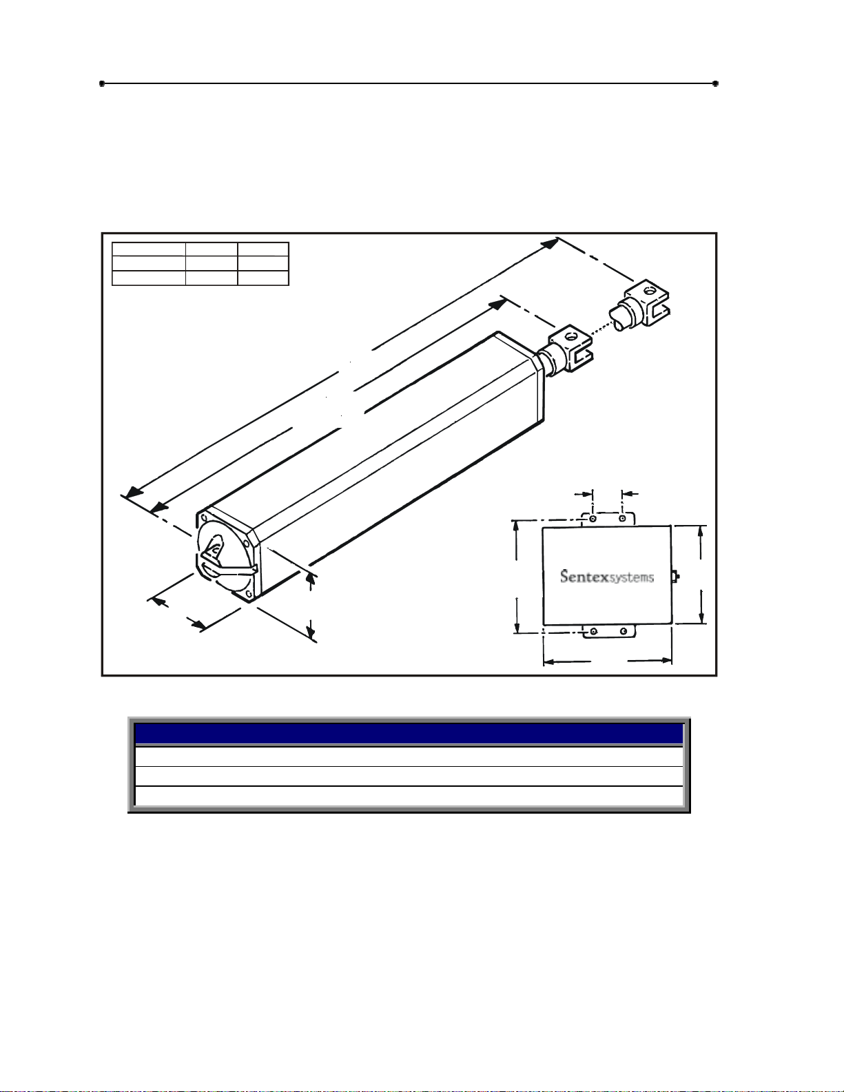
The HL410-21and Hl410L-21 operators are light duty commercial gate operators
designed to operate a typical swing gate. Because operating requirements and gate
construction vary by installation, the capacities shown should be used as a guide to
determine the expected performance of the unit.
HL410-21
HL410L-21
3 1/2”
A
26 1/2
31 3/8
B
38”
48 3/4”
DRIVE UNIT
A
(Retracted)
3 1/2”
B
01-20230F3
CONTROLLER
3”
13 1/2”
12”
16”
Figure 1
MAXIMUM LENGTH VS. MAXIMUM WEIGHT
0 - 8ft 900 lbs
8 - 10ft 900 lbs
10 - 12ft 900 lbs
Table 2
Contact a LiftMaster dealer if your application exceeds any of the recommended limits
to determine the proper unit needed.
! Double Check Operator Capacities!
! Do not use this operator on “walk or pedestrian” gates.
! Do Not Misapply Product. Warranty will be void!
Doc 01-20230
Rev B
Page 5
Specifications & Capacities
5
NOTE
The hydraulic locking is not intended to be a replacement for security type locks.
External lock systems should be used if:
High security is required for the installation.
The length of the gate exceeds 12 feet.
The gate has a large surface area.
The installation area could have a strong or gusty winds.
SPECIFICATIONS
Cycles per hour (Full open & close) 20 maximum
Time to open 19 seconds
Hydraulic (gate) Locking (!) Both Directions
Primary Voltage
Secondary Voltage 24 VAC
Power Consumption 345 W (full load)
Motor R.P.M 1700
Motor Overload 135 °C
Fluid Shell LHM
230 VAC ~1∅ ~ 60hz
Table 3
! It is highly recommended that you reconsider using this type of gate operator on
any solid faced gate, without an external lock system on both the open and closed
position. Strong winds will greatly affect the efficiency of this operator on these
types of gates.
IMPORTANT NOTE
The gate must be level and operate smoothly and freely. If it does not, damage
to the operator may result and the life expectancy will be greatly reduced.
Doc 01-20230
Rev B
Page 6
6
Safety Information
Safety Information
Automatic gate operators provide convenience and security to their users. However,
because these machines can produce high levels of force, it is important that all
installers and users be aware oft he potential hazards associated with improperly
installed or adjusted units.
The information on this page contains various safety precautions and warnings, some
highlighted with this symbol (see left margin). This symbol will identify conditions that
can result in serious injury or death. Take time to read and follow these precautions
and the other information provided.
NOTE
This operator is intended to be a part of a total gate operating system. It is the
responsibility of the purchaser and installer to ensure that the total system is safe
for its intended use.
Installer
BEFORE INSTALLATION
1
Check to see that this is the proper operator for this application. (See page
4).
2
Ensure that the gate has been properly installed and works freely in both
directions. Repair or service any worn or damaged gate hardware.
3
Install the gate operator on the inside of the property and/or fence line.
not
install an operator on the public side of the gate.
4
If the gate is near a residential area, or pedestrian traffic is expected near the
gate, additional safety equipment such as electric gate edges or photocell
detectors must be installed to prevent entrapment. Severe injury or death
can result from entrapment with the gate.
5
Certain types of gates can create greater hazards to pedestrians. Any gate
that has exposed, reachable pinch points or is constructed to allow arms and
legs to pass through it is a potential hazard. These hazards should be
guarded against.
6
Review the operation of the unit and become familiar with the manual
disconnect system and safety features of the unit.
7
Outdoor or easily accessed controls should be of the security type to prohibit
unauthorized use of the gate.
Do
Doc 01-20230
Rev B
Page 7
DURING INSTALLATION
1
Be aware of all moving parts and avoid close proximity to any pinch
points.
2
Disconnect power at the service panel before making any high voltage
power connections.
3
Place controls far enough from the gate so that a user can see but cannot
touch the gate while operating the controls.
4
Place warning signs provided on the gate or in a high visibility area to
alert of automatic gate operation.
AFTER INSTALLATION
1
Make sure the user understands the basic function and safety features of
the system.
2
Leave this manual and the troubleshooting guide with the end user.
End User
1
Periodically check all the safety systems. If these functions are observed
to operate improperly, discontinue use and contact a professional for
service immediately.
Safety Information
7
2
Follow recommended maintenance schedule.
3
Do not allow children to play on or near the gate operating system.
4
Never operate the gate until you have it in full sight.
5
Hydraulic Adjustments
See
on p. 16 for pressure valves and manual
disconnect information.
Doc 01-20230
Rev B
Page 8

8
General Wiring Information
General Wiring Information
DRIVE UNIT,
DRIVE UNIT
SLA VE OPTI ON
CONTROLLER
NOTE
Other wire runs may be required, depending on your application.
CONDUIT, CONTROL
(as required)
CONDUIT, POWER
(3 WIRES)
JUNCTION BOX,
SLA VE OPTI ON
01-20230F4
CONDUIT FOR SLAVE (4 WIRES)
Suggest 12-gauge stranded wire
Figure 2
Wiring information
The distance shown on charts is the total length of wire, measured in feet from
the control panel to the power source.
Supply voltage
(Measure voltage at the unit).
Connect power in accordance with local codes.
Wire tables are based on stranded copper wire. Wire insulation must be
suitable to application.
All units, single and master/slave,
grounding conductor.
Do not
Do not
Do not
run control wires in the same conduit with power wires.
use solid copper wires for controls.
use parallel conductor cable.
If PVC type conduit is used in a single trench, allow a minimum of six (6)
inches between lines.
must
Do not
exceed maximum distance.
be within 10% of the unit’s rating under lead conditions.
must
be properly grounded with a supply
Doc 01-20230
Rev B
Page 9

General Wiring Information
POWER WIRING
Maximum Distance
Single Unit Dual Unit
600 ft 300 ft 14
1000 ft 500 ft 12
1500 ft 750 ft 10
CONTROL WIRING
200 ft 18
400 ft 16
Table 4
Wire Gauge
9
Doc 01-20230
Rev B
Page 10

10
Installation
Installation
Step 1: Gate Stops
The gate must have a permanent gate stop at the full closed position. It is also highly
recommended that there be a gate stop at the determined full open position. These are
to prevent the piston from bottoming in the cylinder and to prolong the unit’s life.
Step 2:
1
2
Gate Brackets
Locate the positions of the front and rear mounting brackets. It is
recommended that these brackets be positioned at the midpoint between the
gate hinges.
It is very important that they be in-line with each other! The operator
must be level.
The two brackets should be welded to the
gate and the post as shown. They can be
welded directly or modified to suit your
particular application.
Do not
operator attached.
weld brackets with
Avoid getting
weld splatter on the piston rod.
Keep piston rod clean and smooth. Avoid nicks.
MODEL HL410-21 MODEL HL410L-21 - 90 OPENING
Front Mounting Bracket
Hinge Point
3” to 3 1/2”
A
5”
Rear Mounting Bracket
32 1/2”
(longest)
(shortest)
10.60
Open
Hinge Point
4.68
47.81
FOR MODEL HL410-21
Dimension A Gate Opening
5” to 5-1/2” 90°
4-1/2”to 5” 100°
4”to 4-1/2” 110°
3-1/2”to 4” 120°
°
3.90
Doc 01-20230
Rev B
Gate shown in the Left-Hand Closed Position
Figure 3
Both Brackets
In Line
01-20230F5
Page 11

Installation
11
Step 3:
Optional Mounting
OUTWARD SWING
WARNING
Do not
into public area. Serious injury could result from someone being hit by the
gate. Use outward swing gates only in applications where the gate will
open into secure area and where the person operating the gate has
control of traffic in the path of the gate.
Do not
gate installation.
A.
Gate stops
1).
B.
Follow Step 2 for mounting of gate brackets. The difference being that the rear
mounting point is 5” to the right of the hinge point instead of 5” to the left as
shown in Step 2 (distance between mounting points is 27-1/2” instead of 371/2”).
C.
The piston rod should be fully retracted when the gate is in the closed position.
The unit should be mounted with the gate in the closed position (see Step 4).
install outward swing gates in applications where gates will swing
use the
must
“Open Only”
be used at both the full open and close positions (see Step
mode of the controller for an outward swing
D.
Proceed to Step 5. Follow wiring for outward swing.
LARGE PILLARS OR WALLS
If the dimension from the centerline of the gate to the outer edge of the pillar or wall
is 3-3/4” or less, you can notch out part of the pillar or wall (see Example A – Figure
4) as shown.
If this dimension is larger than 3-3/4”, then it will be necessary to notch out larger
portion (see Example B – Figure 4) large enough to house the unit. The notch
should be 5” to 8” high. Contact a LiftMaster dealer if your application does not fit
these guidelines.
OPTIONAL MOUNTING - NOTCH AS REQUIRED
01-20230F6
EXAMPLE A EXAMPLE B
Figure 4
Doc 01-20230
Rev B
Page 12

12
Installation
Step 4:
Mounting
1
Manually
open
the gate and attach the unit to the two (2) mounting brackets
(see Figure 5 below).
2
Manually open and close the gate a few times to ensure the mounting brackets
and gate stops are positioned properly with no interference (the unit is shipped
in the disconnect position to allow for this).
3
Mount the controller in a convenient location, within reach of the unit’s 4 ft.
control card. Make sure the cord is not stretched taut (it should have a slight
amount of slack during the full cycle).
4 For Master/Slave Option:
“master unit” and the junction box near the “slave unit”.
Mount both units. Mount the controller near the
REAR MOUNTING PIN
FRONT MOUNTING
CLIP
CONTROLLER
CONTROL CORD
Doc 01-20230
Rev B
C-CLIP
01-20230F7
3’ MAX.
GATE SHOWN CLOSED
Figure 5
Page 13

Installation
(+)
(-)
13
Control Panel Layout
Refer to Table 5 for a description of the control panel parts in Figure 6.
REF. DESCRIPTION PART # REF. DESCRIPTION PART #
CB1 MAIN CIRCUIT BD. MG3101959 CR2 CONTROL RELAY “CLOSE” MG3101963
CB2 MICRO CIRCUIT BD. MG3101960 CR3
CB3
“OPTION” AUTO. CLOSE
CIRCUIT BD.
MG3101961 IF FUSE (.38 A.) MG3101974
PC1 PIN CONNECTOR N/A T TRANSFORMER N/A
C1 CAPACITOR MG3101962 1S POWER DISC. SW. MG3601964
“OPTION” SLAVE UN IT
C2
CAPACITOR
MG3101962 2F FUSE (3 A.) MG3101975
CR1 CONTROL RELAY “OPEN” MG3101963
MODES OF OPERATION
OPEN ONLY: If the gate is closed, when activated, it will open. If the gate is activated while closing, it will reverse to open.
OPEN / CLOSE: If the gate is closed, when activated, it will open. If the gate is open, when activated, it will close. If the
gate is activated while closing, it will reverse to open. If the gate is activated while opening, it will reverse to close.
Table 5
“OPTION” SLAVE DELAY
RELAY
MG3101963
230 VAC.
1
∅
50/60 HZ.
GRD
CB2
C2
T
C1
1F
CR1
2F
23456789
1
WHT
BLK
1S
BRWN
L1
L2
WHT
BLK
DK BLUE
L2 T1 T1T2 T2T3 T3
L1
CR2
10 11 12 13 14
BLK
BRWN
DK BLUE
GRN
BLK
GRD
18 19 20 21
15 16 17
DK BLUE
GRN
WHT
1123445
24 25 26 27 28
22 23
RED
PURP
ORG
LT BLUE
YEL
678910D1
RED
CB1
PC1
D2D2D1
01-20238F5
MOTOR
DK BLUE
BRWN
BLK
GRN/YEL
FIELD CONNECTIONS
Figure 6
NOTE:
All relays and capacitors are shipped separately and must be installed.
Doc 01-20230
Rev B
Page 14

14
Installation
Step 5:
Primary Voltage Wiring
WARNING
Make sure power is disconnected at main power supply and at power
disconnect switch on operator before continuing.
1
Connect 230 vac., single phase power, L1 and L2 to power wiring terminal strip,
and ground to green ground lead wire (see Figure 7).
2
Connect the control cord from the unit to the power wiring terminal strip.
For outward swing, switch brown and black wires to correct logic of
controller (Brown – T3, Black – T2). See also
11.
FOR OPTIONAL MASTER/SLAVE
Connect the control cord from the slave unit to the junction box then connect form
junction box to the power wiring terminal strip, as shown below.
Outward Swing
on page
Doc 01-20230
Rev B
MG5200749
01-20230F9
Figure 7
Page 15

Installation
15
Step 6:
Control Wiring
All controls that are to be added
must
be connected to the control wiring terminal
strip.
Refer to the electrical diagram attached to the inside of the controller door for
accessory wiring.
Please install all safety devices necessary to make this installation as safe
as possible.
Control Wiring Terminal Strip
124568
OPEN/CLOSE
If the gate is closed, when
activated, it will open. If the
gate is open, when activated,
if will close. If the gate is
activated while closing, it will
revers e to open . I f t he gate
is activated while opening, it
will reverse to close.
Reversing Device
Used as Stop
9
OPEN ONLY
If the gate is closed, when
activated, it will open. If the
gate is activated while closing,
it will reverse to open. If the
unit is ac tivated for ope n only,
it must be used in conjunction
with the Stop feature, or a
hazardous and dangerous
condit io n m ay be pr es e nt. Y ou
will also need the optional automatic close timer.
Reversing Device
Will reverse both
directions
Radio Control to
Open / Close
10
D1
D1 D2
24 VAC.
D2
STOP
A device such as a reversing
edge, loop detector, or photo
beam can be used as a Stop
device. It must have a normally
closed contact.
Norm. open “only”
Reversing Device
Slave Unit
Slave
Unit
Motor
2
Normally Closed
If used, remove
jumper 2 to 4
Loop Detector to
Open Only
45
8910
7
GRN
RED
RED
WHITE
D1 D1
910
14
DK BLUE
BRWN
BLK
GRN YEL
4
4
Loop Detector to
Reverse while closing
If used, remove
jumper 6 to 7
123
6789
Junction
Box
YEL
ORG
PURP
78910
RED
RED
D2
10D2
T1
Slave
T2
Terminal
Strip
T3
GRO
5
9
10
5
4
Open Only
Figure 8
6
RED
BLK
GREY
GREY
IT IS RECOMMENDED THAT IF A OPEN ONLY
IS USED, A STOP BE USED WITH IT . . . . .
1
4
Auto. Close Timer
CB3
If used, leave
jumper 6 to 7 in
Stop
If used, remove
jumper 2 to 4
PC1
Open / Close
8
2
4
01-20238F7
4
5
Doc 01-20230
Rev B
Page 16

16
Installation
Step 7:
1
2
3
4
Hydraulic Adjustments
Locate the by-pass valve. Using the hex key supplied, re-engage the by-pass
valve by turning it clockwise as far as possible.
Turn power on at main power supply and at power disconnect switch. The
controller has a 7 second delay form power-up until a signal can be received.
With gate open, activate the unit to close. Using a flat blade screwdriver, slowly
turn the close pressure valve counter-clockwise until the gate begins to move,
then adjust it ¼ to ½ turn more. (Unit is shipped with pressure valves set at
minimum).
NOTE
Since the unit’s cycle time has yet to be adjusted, it may shut off too soon
or may run longer than desired.
Locate the open pressure valve. Activate the unit to open and adjust it in the
same manner as the close direction.
WARNING
The open & close pressure valves must be adjusted properly. They should
develop enough force to open and close the gate properly. If the gate
meets an obstruction there will be a minimum amount of force applied.
Check this by holding the gate when it is closing and opening.
For manual operation of the gate,
valve counter-clockwise
turn the
Never
by-pass valve clockwise.
adjust the open and/or close pressure valves to their maximum
to disconnect the unit. To
use the hex key and turn the
reconnect
by-pass
the unit
setting. Always use the minimum setting required to move the gate. If
strong wind loads are a possibility, increase the run time –
not
the
pressure valves.
Plastic Cover
“Top View”
Close Pressure Valve
Disconnect Key
By-Pass Valve
Doc 01-20230
Rev B
Open Pressure Valve
Figure 9
“Bottom View”
01-20230F11
Page 17

Installation
17
Step 8:
Adjustments
1
Locate the cycle timer “pot” on the control panel. This pot determines the
length of time the unit will run. Adjust it so the unit will fully open and close the
gate properly. Allow a few seconds for slippage against the gate stops.
2 Optional:
delay relay, locate the master/slave delay “pot” on the control panel. This pot
determines the close time delay between two units (i.e. the master closes first).
Adjust this “pot” to the desired delay time.
3 Optional:
determines how long the gate will stay open before it automatically closes.
Adjust this to the desired time.
If you have a master/slave system and have added the master/slave
NOTE:
Reversing edges, obstruction sensors and inductive loop detectors should
be used with this feature to prevent injury or property damage.
Both units will open at the same time.
Locate the auto close timer “pot” on the control panel. This pot
--
-
Figure 10
01-20230F12
Doc 01-20230
Rev B
Page 18

18
Installation
Step 9:
Rod Cover
Install the rod cover over the piston rod, as shown.
IMPORTANT NOTE:
The cover must be installed to keep the piston rod clean
and nick-free.
Figure 11
01-20230F13
Doc 01-20230
Rev B
Page 19

System Check-Out
System Check-Out
LiftMaster strongly recommends that at this time you check out the entire system.
1
Make sure the unit fully opens and closes the gate properly.
2
Check all controls that activate the gate to ensure they are working properly.
3
It is extremely important that all safety devices be checked and double
checked.
4
Double check the manual operation features and pressure valves of the
system.
19
NOTE:
Troubleshooting Guide.
If a problem should arise, see the Model HL410-21
AND FINALLY...
Install the gate caution on both the inside and outside of the gate where
they can be easily seen.
LiftMaster recommends that you pad-lock the controller door. Inform the
customer of this recommendation.
Make sure the unit and controller are free of grease or dirt. Clean if
necessary.
Clean up the area around the gate.
Look around for any tools or equipment that may be left.
Please leave this manual and the troubleshooting guide with the customer.
Let the customer know you’ve finished installing the unit and review all
pertinent information with them, including safety features and maintenance.
Limited One-Year Warranty
LiftMaster gate operators are warranted against deficiencies in material and workmanship for a
period of one (1) year from date of purchase, providing recommended installation and
maintenance procedures are followed. This warranty is in lieu of all other warranties expressed
or implied (some states do not allow limitations on how long an implied warranty lasts, so this
limitation may not apply to you) and shall be considered void if damage was due to improper
installation or use, connection to improper power source, or if damage was caused by fire, flood
or lightning. The manufacturer will not be responsible for any labor charges incurred in the
removal or replacement of deficient parts.
In case of failure due to deficiencies in material or workmanship during the warranty period, the
completer gate operator will be repaired or replaced at the manufacturer’s option. New factory
rebuilt replacements will be used. Replacement parts are warranted for the remaining portion of
the original warrant period. LiftMaster will pay freight on our return of repaired or replaced items
in warranty.
This warranty gives you specific rights, and you may also have other rights which vary form state
to state.
Doc 01-20230
Rev B
Page 20

20
Parts List
Parts List
Hatch Kit
MG49258
End Cap
MG49196
Power Cord
MG24719
Mounting Pin Kit
MG49136
Disconnect
Hex Key
MG5100812
Drive Unit
Mounting Clip
MG5100816
Rod Cover
MG5100813
Connector Kit
MG49133
Fuse Kit
Relay
Fuse Kit
MG49135
MG3101963
MG49135
Disconnect
Switch
MG3601964
C-Clip Kit
Rear Mounting Bracket
MG5100815
Capacitor
MG3101962
Main Circu it Board
MG49070 or MG491 1 0
MG49136
Front Mounting Bracket
MG5100814
Micro Circuit Board
MG49071 OR MG49111
Circuit Bd.
Mounting Kit
MG49170
Automatic
Close Timer Board
(Optional)
MG49072 OR MG49112
Control
Box
Control
Panel
NOTE:
listed.
Doc 01-20230
Rev B
Power Termina l Strip
MG5100586
Control Terminal Strip
MG4100994
01-20230F14
Figure 12
The parts listed above are available for replacement. Order by part number
Page 21

Required Maintenance Services
Required Maintenance Services
21
Maintenance Service Required Every ΖΖ
Gate Inspect for wear and/or damage
Manual Operation Check & adjust if required
Close Pressure Check & adjust if required
Open Pressure Check & adjust if required
Accessories Inspect & test
Safety
Devices
Inspection and service should be performed any time a malfunction is observed
or suspected.
High cycle usage will require more frequent service checks.
Always Disconnect Power When Servicing!
Inspect & test
ΖΖ
ΖΖΖΖ
Table 6
1
Month
"
"
"
"
6
Months
"
"
12
Months
Complete
Check
Doc 01-20230
Rev B
Page 22

COPYRIGHT 2001
ALL RIGHTS RESERVED
This document is protected by copyright and may not be copied or adapted without the prior written
consent of LiftMaster. This documentation contains information proprietary to LiftMaster and such
information may not be distributed without the prior written consent of LiftMaster. The software and
firmware included in the LiftMaster product as they relate to this documentation are also protected by
copyright and contain information proprietary to LiftMaster.
FOR TECHNICAL SUPPORT
Call our toll free numbers:
(800) 323-2276
(800) 998-9197
Installation and service information is
available six days a week.
TO ORDER REPAIR PARTS
Call our toll free numbers:
(800) 528-2806
(800) 998-9197
Prepare to provide the following
information when ordering repair parts:
Part Number
#
Part Name
#
Model Number
#
 Loading...