

Page 1
OWNER'S MANUAL
LOGIC CONTROL
L
C2 Wiring
F A C T O R Y S E T
See pages 15 and 16
for other wiring
configurations
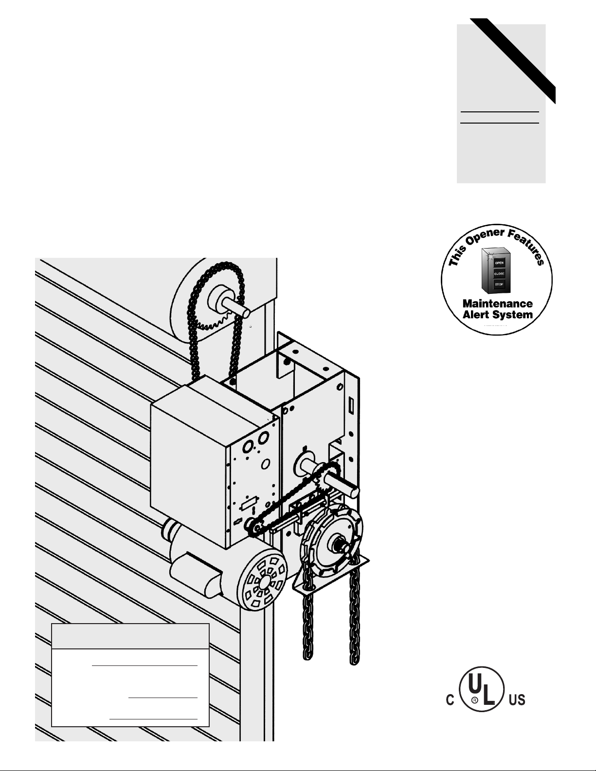
LISTED DOOR OPERATOR
41B6
MODELS:
J H HJ
LOGIC CONTROL (VER. 2.0)
INDUSTRIAL DUTY DOOR OPERATOR
PATENT PENDING
The Maintenance Alert System
allows the installer to set an internal
Maintenance Cycle Counter. An LED
on the 3-button station will signal when
the set number of cycles is reached or
when the opener requires immediate
service.
TM
2 YEAR WARRANTY
Serial #
(located on electrical box cover)
Installation Date
Wiring Type
NOT FOR RESIDENTIAL USE
Page 2
TABLE OF CONTENTS
SPECIFICATIONS
Packing List . . . . . . . . . . . . . . . . . . . . . . . . . . . . . .2
Motor Specification . . . . . . . . . . . . . . . . . . . . . . . . .3
Electrical Specifications . . . . . . . . . . . . . . . . . . . . .3
Mechanical Specifications . . . . . . . . . . . . . . . . . . . .3
Safety Specifications . . . . . . . . . . . . . . . . . . . . . . .3
Weights & Dimensions . . . . . . . . . . . . . . . . . . . . . .3
PREP
ARATION
Track Assembly . . . . . . . . . . . . . . . . . . . . . . . . . . . . . .4
Powerhead Attachment . . . . . . . . . . . . . . . . . . . . . . . .4
Trolley Carriage/ Chain Attachment . . . . . . . . . . . . . . .4
INST
ALLATION INSTRUCTIONS
Mounting Header Bracket . . . . . . . . . . . . . . . . . . . . . .5
Mounting Operator . . . . . . . . . . . . . . . . . . . . . . . . . . . .5
Operator Support . . . . . . . . . . . . . . . . . . . . . . . . . . . . .6
Straight Arm Attachment . . . . . . . . . . . . . . . . . . . . . . . .6
ENTRAPMENT PROTECTION
ACCESSORIES
Sensing Edges & Photo Eyes . . . . . . . . . . . . . . . . . . .7
LIMIT SWITCH
ADJUSTMENT
Limit Location . . . . . . . . . . . . . . . . . . . . . . . . . . . . . . . .7
Adjustment . . . . . . . . . . . . . . . . . . . . . . . . . . . . . . . . . .7
POWER & CONTROL
WIRING
Safety Warnings . . . . . . . . . . . . . . . . . . . . . . . . . . . . . .8
Power Wiring . . . . . . . . . . . . . . . . . . . . . . . . . . . . . . . .9
Ground Wiring . . . . . . . . . . . . . . . . . . . . . . . . . . . .9
Control Station Wiring . . . . . . . . . . . . . . . . . . . . . . .9
Radio Controls . . . . . . . . . . . . . . . . . . . . . . . . . . . .9
Mounting Instructions . . . . . . . . . . . . . . . . . . . . . . .9
Optional Control Mounting . . . . . . . . . . . . . . . . . . .9
Optional Control Wiring . . . . . . . . . . . . . . . . . . . . .32
BRAKE ADJUSTMENT
Brake Parts . . . . . . . . . . . . . . . . . . . . . . . . . . . . . .10
CLUTCH
ADJUSTMENT
Clutch Parts . . . . . . . . . . . . . . . . . . . . . . . . . . . . . .10
Clutch Adjustment . . . . . . . . . . . . . . . . . . . . . . . . .10
WIRING DIAGRAMS
1 PH Control Connections . . . . . . . . . . . . . . . . . . .13
3 PH Control Connections . . . . . . . . . . . . . . . . . . .14
1 PH Wiring . . . . . . . . . . . . . . . . . . . . . . . . . . . . . .11
3 PH Wiring . . . . . . . . . . . . . . . . . . . . . . . . . . . . . .12
ST
ANDARD PROGRAMMING
Wiring Type . . . . . . . . . . . . . . . . . . . . . . . . . . . . . .15 & 16
RPM Sensor . . . . . . . . . . . . . . . . . . . . . . . . . . . . . .17
Maximum Run Timer . . . . . . . . . . . . . . . . . . . . . . .17
Maintenance Alert System . . . . . . . . . . . . . . . . . . .18
OPTIONAL
PROGRAMMING
Mid Stop . . . . . . . . . . . . . . . . . . . . . . . . . . . . . . . . .18
Timer to Close . . . . . . . . . . . . . . . . . . . . . . . . . . . .19
Red Green Warning Lights . . . . . . . . . . . . . . . . . . .19
Board Illustration . . . . . . . . . . . . . . . . . . . . . . . . . .20
REPLACEMENT P
ARTS & MAINTENANCE
Trouble Shooting Guide . . . . . . . . . . . . . . . . . . . . .21 & 22
Maintenance Schedule . . . . . . . . . . . . . . . . . . . . . .23
Customer Service Contact Information . . . . . . . . . .23
Electrical Box parts . . . . . . . . . . . . . . . . . . . . . . . . .24 & 25
Chassis Parts (J) . . . . . . . . . . . . . . . . . . . . . . . . . .26 & 27
Chassis Parts (H) . . . . . . . . . . . . . . . . . . . . . . . . .28 & 29
Chassis Parts (HJ) . . . . . . . . . . . . . . . . . . . . . . . .30 & 31
PACKING LIST
PART #
19-50106M
40-6000
77-10704
10-10463
14-10466
27-10199
80-207-19
27-10199
14-12133
02-103L
40-65
QTY.
1
1
1
1
1
1
1
2
1
1
2
DESCRIPTION
#50 CHAIN, MASTER LINK
DOOR OPERATOR LABEL
PARTS BAG
KEY HOLE BRACKET
CLEAR PLASTIC BAG
CABLE TIE
KEY 1/4 X 1-1/2"LONG
CABLE TIE
PARTS BOX
3 PUSH BUTTON STATION
DOOR EDGE CAUTION LABEL
Before beginning your installation check that all
components were supplied and received undamaged.
Before attempting to install, operate or maintain the operator, you must read and fully understand this manual and follow all safety instructions.
These instructions are intended to highlight certain safety related issues. These instructions are not intended to be comprehensive. Because each application is unique, it is the
responsibility of the purchaser, designer, installer and end user to ensure that the total
door system is safe for its intended use.
2
P
ART #
19-50106M
40-6000
77-10897
10-10893
14-10466
27-10199
80-207-19
27-10199
19-10929-25
14-12133
02-103L
40-65
QTY
.
1
1
1
1
1
1
1
2
1
1
1
2
DESCRIPTION
#50 CHAIN, 106 PITCH
DOOR OPERATOR LABEL
PARTS BAG
CHAIN RETAINING BRACKET
PLASTIC BAG
CABLE TIE 5 1/2IN
KEY 1/4 X 1-1/2"LONG
CABLE TIE 5 1/2IN
HAND CHAIN 25 FT. LEN
PARTS BOX
3 PUSH BUTTON STATION
DOOR EDGE CAUTION LABEL
DESCRIPTION
25 FT HAND CHAIN
#50 CHAIN, 106 PITCH
KEY HOLE BRACKET
CHAIN RETAINING BRACKET
3 PUSH BUTTON STATION
PARTS BOX
PART #
19-10929-25
19-50106M
10-10463
10-10893
02-103L
14-12133
QTY
1
1
1
1
1
1
PACKING LIST K77-14145 - MODEL H
PACKING LIST K77-13937 - MODEL J
PACKING LIST K77-14918 - MODEL HJ
Page 3
3
MOTOR
TYPE: .................................Continuous duty
HORSEPOWER: ................1/3, 1/2, 3/4 & 1 Hp
SPEED:...............................1725 RPM
VOLTAGE:..........................115, 208-230 Single phase
230,380,460, 575
Three Phase
CURRENT:..........................See motor nameplate
MECHANICAL
DRIVE REDUCTION: ..Primary: Heavy duty (5L) V-Belt.
Secondary: #48 chain/sprocket Output: #50 chain
OUTPUT SHAFT SPEED:.....36 R.P.M.
DOOR SPEED: ......................6 - 7” per sec.
depending on door
BRAKE: (Optional) ...............Solenoid actuated disc
brake
BEARINGS: ...........................Output Shaft: Shielded
Ball Bearing. Clutch Shaft: IronCopper sintered and
oil impregnated.
HAND CHAIN WHEEL: .........Left or right handing
Models H and HJ only.
SAFETY
DISCONNECT :
Model J: Floor level disconnect for emergency manual
door operation.
Model H: Floor level chain hoist with electrical interlock
for emergency manual door operation.
Model HJ: Includes both floor level disconnect
systems stated above.
SAFETY PHOTO EYES: (Optional) Thru beam or retro
reflective devices used to provide non-contact safety
protection. Directly interface to Lift Master CPS-L or
CPS-LN4 Commercial Protector Systems.
SAFETY EDGE:............(Optional) Electric or pneumatic
sensing device attached to the bottom edge of door.
A REVERSING DEVICE IS STRONGLY RECOMMENDED FOR ALL COMMERCIAL OPERATOR
INSTALLATIONS. REQUIRED WHEN THE 3 BUTTON
CONTROL STATION IS OUT OF SIGHT OF DOOR
OR ANY OTHER CONTROL (AUTOMATIC OR MANUAL) IS USED.
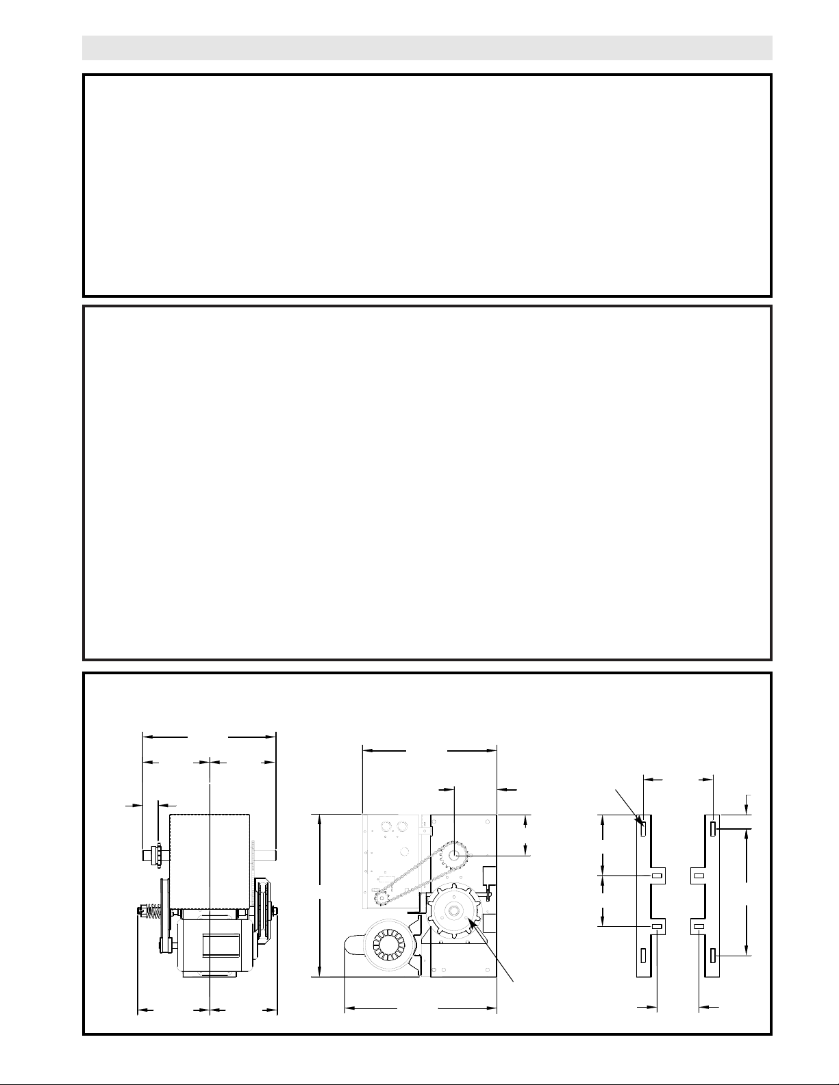
SPECIFICATIONS
ELECTRICAL
TRANSFORMER:.............24VAC Secondary
CONTROL STATION:......NEMA 1 three button station.
OPEN/CLOSE/STOP W/ LED
WIRING TYPE:.................C2 (Factory Shipped)
Momentary contact to OPEN & STOP, constant pressure to CLOSE, open override plus wiring for sensing
device to reverse. See pages 16, 17 and 18 for
optional wiring types and operating modes.
LIMIT ADJUST: ................Linear driven, fully
adjustable screw type cams. Adjustable to 24 feet.
17.63”
7.56”
5.50”
6.59”
13.75”
1.50”
4.56”
4.41”
4.63”
14.60”
16.50”
14.44”
7.27”
8.83”
7.31”
A
A
A
A
B
B
B
B
MOUNTING DIMENSIONS
A - Wall Mounting
B - Bracket Mounting (rolling door)
WEIGHTS AND DIMENSIONS
HANGING WEIGHT: .........80-110 LBS.
Hand Chain Wheel
present with Models
H and HJ only.
7.17”
2.00”
3/8” BOLT
Page 4
CAUTION
WARNING
IMPORTANT SAFETY NOTES
2-1/4"
FIGURE 1
Shaft Support Bracket
with Bearing (Not Supplied)
Door Sprocket
WARNING
TO AVOID DAMAGE TO DOOR AND OPERATOR,
MAKE ALL DOOR LOCKS INOPERATIVE. SECURE
LOCK(S) IN "OPEN" POSITION.
IF THE DOOR LOCK NEEDS TO REMAIN FUNCTIONAL, INSTALL AN INTERLOCK SWITCH.
DO NOT CONNECT ELECTRIC POWER UNTIL
INSTRUCTED TO DO SO.
SITE PREPARATIONS
It is imperative that the wall or mounting surface provide adequate support for the operator.
This surface must:
a) Be rigid to prevent play between operator and
door shaft.
b) Provide a level base.
c) Permit the operator to be fastened securely and
with the drive shaft parallel to the door shaft.
The safety and wear of the operator will be adversely
affected if any of the above requirements are not met.
KEEP DOOR BALANCED. STICKING OR BINDING
DOORS MUST BE REPAIRED. DOORS, DOOR
SPRINGS, CABLES, PULLEYS, BRACKETS AND
THEIR HARDWARE MAY BE UNDER EXTREME TENSION AND CAN CAUSE SERIOUS PERSONAL
INJURY. CALL A PROFESSIONAL DOOR SERVICEMAN TO MOVE OR ADJUST DOOR SPRINGS OR
HARDWARE.
For metal buildings, fasten 2 x 2 x 3/16 (or larger)
angle iron frames to the building purlins. Retain 51/2 between frames. See Figure 1.
ALL DOORS INTENDED TO BE MOTOR OPERATED
SHOULD BE MANUFACTURED WITH SOLID DOOR
SHAFTS.
OPERATOR PREPARATION
Both J and H series operators have dual output
shafts and may be mounted on either the right (standard) or left side of door, and in either a vertical
(standard) or horizontal mounting position. If you
need to move the drive sprocket, loosen BOTH set
screws, remove the sprocket and key, and place on
the opposite side of the drive shaft. Be sure to tighten BOTH set screws securely
Hand Chain Handing
For models H and HJ with manual hoist hand chain
systems, the handing of the operator must be determined at the time of order. The handing is indicated by last letter of the model name (R or L). The
hand chain wheel can not be switched on site.
If your installation causes the hand chain to hang in
the door opening, hook the chain off to the side
near the top of the door jamb.
Output
Shaft
5-1/2”
(2) Set
Screws
Key
Drive
Sprocket
4
Page 5
5
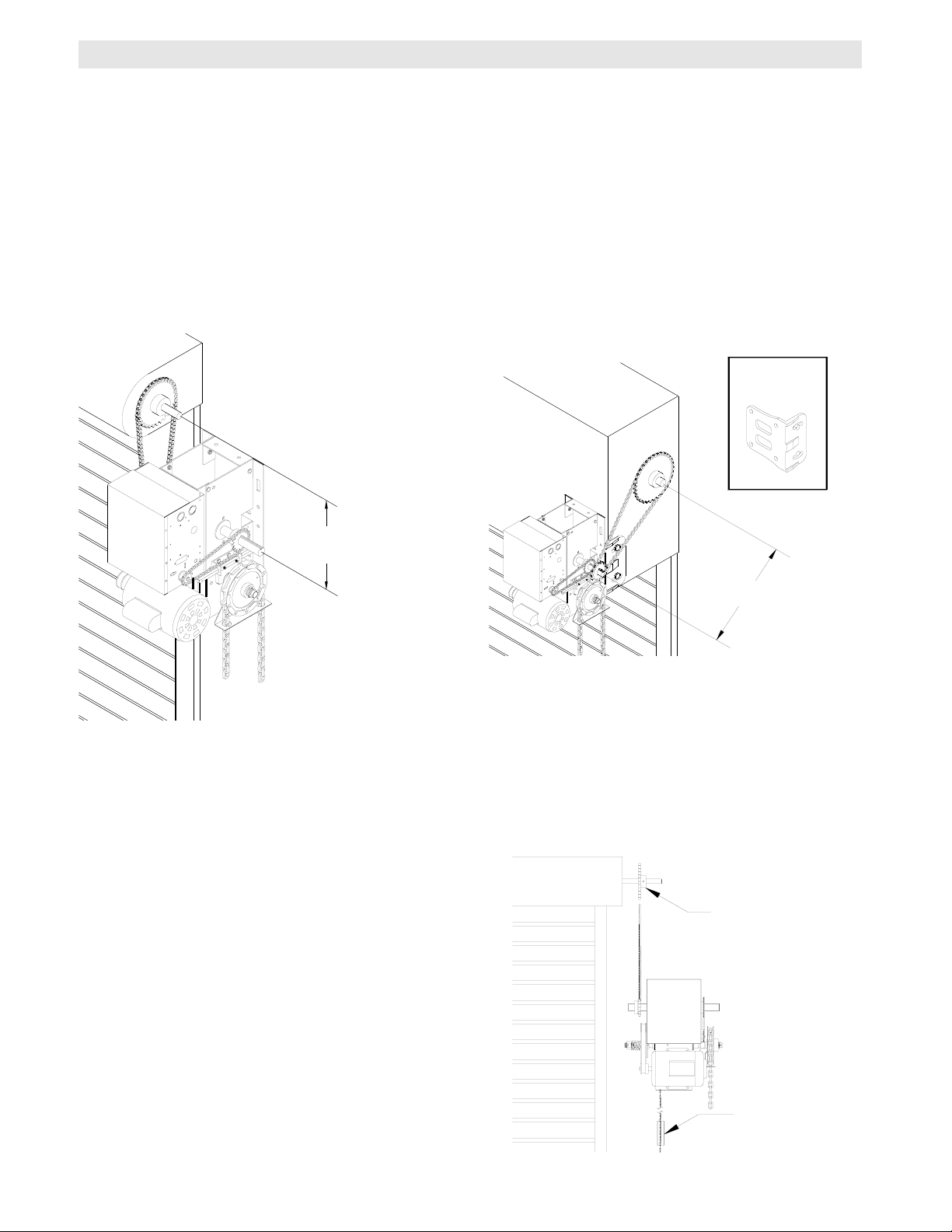
1a. Wall Mounting
The operator should generally be installed below
the door shaft, and as close to the door as possible. The optimum distance between the door shaft
and operator drive shaft is between 12” - 15”. Refer
to Figure 3.
OPERATOR MOUNTING
IMPORTANT: The shelf or bracket must provide adequate support, prevent play between
operator and door shaft, and permit operator
to be fastened securely and with the drive
shaft parallel to the door shaft.
1b. Bracket or Shelf Mounting
The operator may be mounted either above or
below the door shaft. The optimum distance
between the door shaft and operator drive shaft is
between 12” - 15”. Refer to Figure 4.
1c. Place door sprocket on the door shaft. Do not
insert the key at this time.
2. Place drive sprocket on the appropriate side of the
operator. Do not insert the key at this time.
3. Wrap drive chain around door sprocket and join
roller chain ends together with master link.
4. Raise operator to approximate mounting position
and position chain over operator sprocket.
5. Raise or lower operator until the chain is taut (not
tight). Make sure the operator output shaft is parallel to door shaft and sprockets are aligned. When
in position, secure the operator to wall or mounting
bracket.
6. Align sprockets and secure, (see Figure 5).
FIGURE 4FIGURE 3
Before your operator is installed, be sure the door has been properly aligned and is working smoothly. The operator may be wall mounted or mounted on a bracket or shelf. If necessary, refer to the operator preparations on
page 3. Refer to the illustration and instructions below that suits your application.
FIGURE 5
Typical Right Hand
Wall Mounted Operator
Optimum Distance
12 - 15”
Optimum Distance
12 - 15”
OPTIONAL
Mounting Bracket
P/N 08-9098
Be sure door
sprocket is properly aligned with
drive before securing to the shaft.
Chain Keeper
Page 6
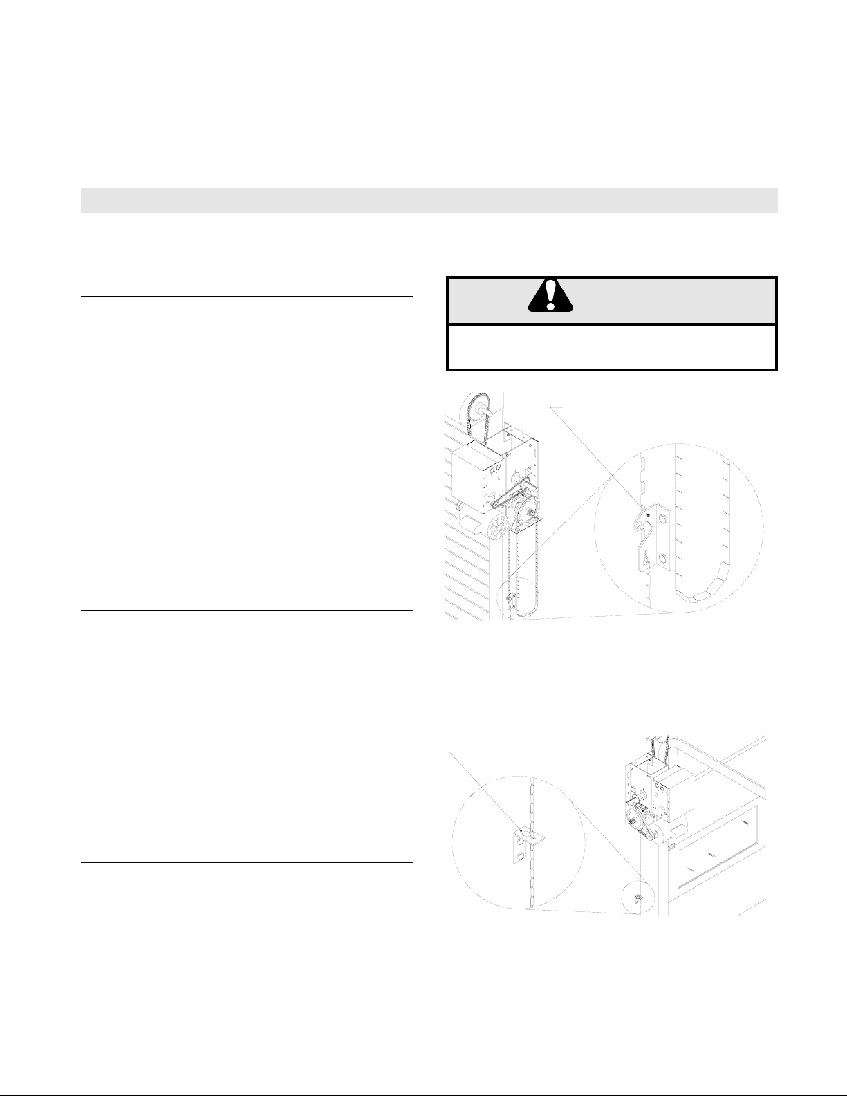
These operators are equipped with a manual hoist. An
electrical interlock will disable the electrical controls
when the hoist is used. To operate the hoist:
1. Pull the disconnect chain (small chain) to engage
the hoist mechanism. The disconnect chain may be
locked in position by slipping the end through the keyhole of the chain keeper mounted on the wall.
2. Operate the door in the desired direction by pulling
on one side or the other of the continuous loop hoist
chain (large chain).
3. The disconnect chain must be released from the
chain keeper before the door will operate again electrically.
6
7. Install Hand Chain (Models H and HJ only)
Place hand chain around hand chain wheel. Be
sure to pass it through both openings in the chain
guide. Remove enough links so chain hangs
approximately two feet above the floor
EMERGENCY MANUAL OPERATION
This operator has provisions for manually operating the door in case of emergency or power failure. Refer to the
appropriate instructions below for your model operator.
Model H
Model J
This operator has a floor level disconnect chain to disconnect the door from the door operator.
1. To disengage, pull the chain and secure in the dis-
engaged position by slipping the end through the keyhole bracket mounted on the wall. Or if emergency
egress device is used, pull handle to disengage operator from door.
2. The door may now be pushed up or pulled down
manually. Release the disconnect chain to operate the
door again electrically.
8. Mount Chain Keeper / Keyhole Bracket
Using suitable hardware mount the chain keeper
approximately 4 feet above the floor, near the free
hanging chain. Remove disconnect sash chain
from bag and place the end through the keyhole in
the the chain keeper. Remove excess links if necessary.
Model HJ
This operator includes both a floor level disconnect
chain to disconnect the door from the door operator
and and a disconnect chain with manual hoist to electrically disable the operator controls.
1.
Refer to Model H instructions for hoist operation.
2.
Refer to Model J instructions for manual operation.
Manual Disconnect for Models J and HJ
Electrical Interlock with Hoist for Models H and HJ
TURN OFF POWER TO THE OPERATOR BEFORE
MANUALLY OPERATING YOUR DOOR.
WARNING
CAUTION
WARNING
WARNING
Chain Keeper
(with pad locking provisions)
Keyhole Bracket
CAUTION
Page 7
7
TO AVOID SERIOUS PERSONAL INJURY OR DEATH
FROM ELECTROCUTION, DISCONNECT ELECTRIC
POWER BEFORE MANUALLY MOVING LIMIT NUTS.
WARNING
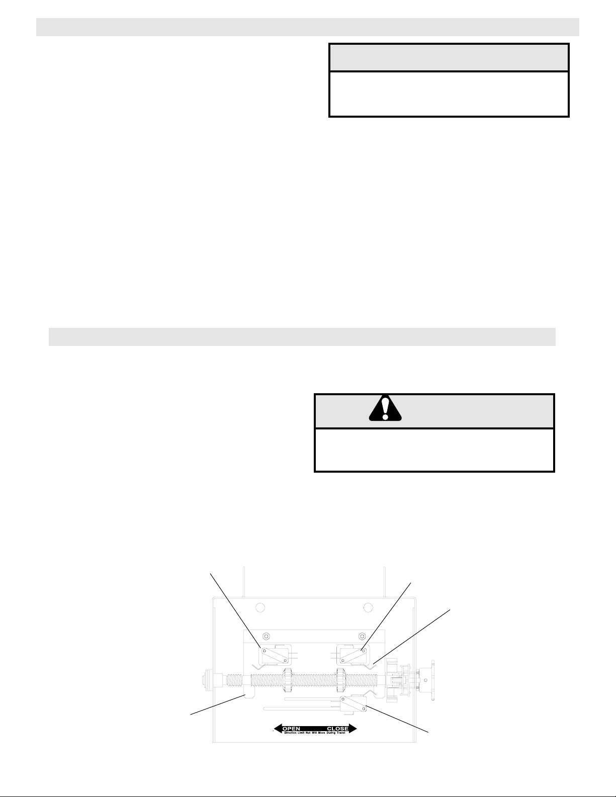
LIMIT SWITCH ADJUSTMENT
MAKE SURE THE LIMIT NUTS ARE POSITIONED BETWEEN THE LIMIT SWITCH ACTUATORS BEFORE
PROCEEDING WITH ADJUSTMENTS.
If other problems persist, call our toll-free number for
assistance - 1-800-528-2806.
1. To adjust limit nuts depress retaining plate to allow
nut to spin freely. After adjustment, release plate
and ensure it seats fully in slots of both nuts.
2. To increase door travel, spin nut away from actu-
ator. To decrease door travel, spin limit nut toward
actuator.
3. Adjust open limit nut so that door will stop in open
position with the bottom of the door even with top
of door opening.
4. Repeat Steps 1 and 2 for close cycle. Adjust close
limit nut so that actuator is engaged as door fully
seats at the floor.
Retaining Plate
CLOSE Limit Switch
SAFETY
(Aux. Close) Limit Switch
OPEN Limit Switch
Actuator
PHOTO EYES & SENSING EDGES
Sensing devices supplied for door industry type operators
with an isolated normally open (N.O.) dry contact output are
compatible with your operator. This includes through beam
and retro reflective photo eyes and pneumatic and electric
edges. If your door does not have bottom safety photo eyes
or safety edge and you wish to add a safety device to your
application, please contact your local LiftMaster Authorized
Dealer.
If not pre-installed by the door manufacturer, mount the sensing edge on the door according to the instructions provided
with the edge. The sensing edge may be electrically connected by either coiled cord or take-up reel.
Important Notes:
a) Proceed with Limit Switch Adjustments before making
any sensing edge wiring connections to operator as
described below.
b) Electrician must hardwire the junction box to the operator
electrical box in accordance with local codes.
ENTRAPMENT PROTECTION ACCESSORIES (OPTIONAL)
WIRING:
For wiring of your sensing device to the operator, refer to
the wiring diagrams supplied on pages 13 and 14. See
field connection terminals identified as Reversing Edge.
TAKE-UP REEL: Take-up reel should be installed 12"
above the top of the door.
COIL CORD: Connect operator end of coil cord to junction box (not supplied) fastened to the wall approximately
halfway up the door opening.
IT IS STRONGLY RECOMMENDED THAT A
SAFETY PHOTO EYE OR SENSING EDGE BE
USED IN CONJUNCTION WITH THE OPERATOR.
NOTICE
WARNING
Page 8
8
DISCONNECT POWER AT THE FUSE BOX BEFORE
PROCEEDING.
OPERATOR MUST BE PROPERLY GROUNDED AND
CONNECTED IN ACCORDANCE WITH LOCAL ELECTRICAL CODES. NOTE: THE OPERATOR SHOULD
BE ON A SEPARATE FUSED LINE OF ADEQUATE
CAPACITY.
ALL ELECTRICAL CONNECTIONS MUST BE MADE
BY A QUALIFIED ELECTRICIAN.
WARNING
TO AVOID DAMAGE TO DOOR AND OPERATOR,
MAKE ALL DOOR LOCKS INOPERATIVE. SECURE
LOCK(S) IN "OPEN" POSITION.
IF THE DOOR LOCK NEEDS TO REMAIN FUNCTIONAL, INSTALL AN INTERLOCK SWITCH.
Before installing power wiring or control stations be sure to follow all specifications and warnings described below. Failure to do so may result in severe injury to persons and/or damage
to operator.
The operator electrical box is only to be accessed by trained “LIFTMASTER” technicians. If
service is required contact your local LIFTMASTER dealer.
Do not install any wiring or attempt to run the operator without consulting the wiring diagram.
Install the optional Reversing Edge before proceeding with the Control Station installation.
Remove the cover from the electrical enclosure. Inside this enclosure you will find the wiring
diagram(s) for your unit. Refer to the diagram (glued on the inside of the cover) for all connections described below. If this diagram is missing, call the number on the back of this manual.
DO NOT INSTALL ANY WIRING OR ATTEMPT TO RUN THIS OPERATOR WITHOUT CONSULTING THE WIRING DIAGRAM.
IMPORTANT SAFETY NOTES
INSTALL POWER WIRING & CONTROL STATION
ANY MAINTENANCE TO THE OPERATOR OR IN THE
AREA NEAR THE OPERATOR MUST NOT BE PERFORMED UNTIL DISCONNECTING THE ELECTRICAL POWER AND LOCKING-OUT THE POWER VIA,
THE MAIN DISCONNECT SWITCH. UPON COMPLETION OF MAINTENANCE THE AREA MUST BE
CLEARED AND SECURED, AT THAT TIME THE UNIT
MAY BE RETURNED TO SERVICE.
WARNING
INSTALL THE CONTROL STATION IN LINE OF SIGHT WITH
THE DOOR, BUT AWAY FROM THE DOOR AND ITS HARDWARE. IF CONTROL STATION CANNOT BE INSTALLED
WHERE DOOR IS VISIBLE, OR IF ANY DEVICE OTHER THAN
THE CONTROL STATION IS USED TO ACTIVATE THE DOOR,
A REVERSING DEVICE MUST BE INSTALLED ON THE BOTTOM OF THE DOOR. FAILURE TO INSTALL A REVERSING
DEVICE UNDER THESE CIRCUMSTANCES MAY RESULT IN
SERIOUS INJURY OR DEATH.
WARNING
WARNING
WARNING
WARNING
Page 9
9
POWER WIRING CONNECTIONS
1. Connect power wires coming from the main to the
captive terminal block in the electrical box enclosure
marked with the label shown below.
2. Be sure to run all power wires through the conduit
hole in the electrical box enclosure marked with the label
shown below.
POWER WIRING
CONTROL STATION WIRING
CONTROL WIRING CONNECTIONS
1. Connect control wires to the TB1 terminal block
located on the Printed Circuit Board (shown below).
GROUND WIRING
ON THREE PHASE MACHINES ONLY:Incorrect
phasing of the power supply will cause the motor to
rotate in the wrong direction.
4 Feet
Approximate
MOUNTING INSTRUCTIONS
Control
Station
Optional
Controls
1. Mount Control Stations no further than (12”) from
each other.
2. Mount Control Stations (12”) from the door enclosure.
3. Mount WARNING NOTICE beside or below the
Control Station.
4. Mount MAINTENANCE ALERT label to either side
of control station.
1. Connect earth ground to the chassis ground screw in
the electrical box enclosure marked with the label shown
below.
2. Use same conduit entry into the electrical box as the
power wiring.
IMPORTANT: THIS UNIT MUST BE PROPERLY
GROUNDED. FAILURE TO PROPERLY GROUND
THIS UNIT COULD RESULT IN ELECTRIC SHOCK
AND SERIOUS INJURY.
RADIO CONTROLS
INSTALL POWER WIRING & CONTROL STATION (CONT’D)
1
2
3
4
5
6
7
8
9
10
11
12
13
SBC
CMN
STOP
CLOSE
OPEN
REV
IR
MAS
CMN
24AC+
24AC-
SINGLE BUTTON CONTROL
INTERLOCK
INTERLOCK
COMMON
STOP
CLOSE
OPEN
REVERSE
INFRARED PHOTO EYES
MAINTENANCE ALERT SYSTEM
COMMON
24 VOLT AC
24 VOLT AC
On all models with B2 control wiring, a terminal bracket
marked R1 R2 R3 is located on the outside of the electrical enclosure. Any commercial type LiftMaster brand
receiver may be mounted to this bracket. The operator
will then open a fully closed door, close a fully open
door, stop an opening door, and reverse a closing door
from the radio transmitter. In TS control wiring the operator will only open the door or reset the timer to close.
However, for additional door control from a 3 button
transmitter, a commercial three-channel radio receiver
(with connections for OPEN/CLOSE/STOP) is recommended.
2. Be sure to run all control wires through the conduit
hole in the electrical box enclosure marked with the label
shown below.
3. Apply power to the operator. Press OPEN push button
and observe direction of door travel and then Press the
STOP button.
If door did not move in the correct direction, check for
improper wiring at the control station or between operator
and control station.
13 24AC-
12 24AC+
11 CMN
10 MAS
9 IR
8 REV
7 OPEN
6 CLOSE
5 STOP
4 CMN
3
2
1 SBC
2
3
40-10033B
ANY MAINTENANCE OTHER THAN
PROGRAMMING OPTIONS IN THE OPERATOR
OR IN THE AREA NEAR THE OPERATOR MUST
NOT BE PERFORMED UNTIL DISCONNECTING
THE ELECTRICAL POWER AND LOCKING-OUT
THE POWER VIA, THE MAIN DISCONNECT
SWITCH. UPON COMPLETION OF
MAINTENANCE THE AREA MUST BE CLEARED
AND SECURED, AT THAT TIME THE UNIT MAY
BE RETURNED TO SERVICE.
Maintenance Alert
System
If light is Flashing,
it is time for routine
Door and Opener
Maintenance.
If light is Steady
On, call for
immediate service.
Service every
________ cycles.
TM
Page 10

10
BRAKE ADJUSTMENT
A solenoid brake is optional on all models, and is optional on 1/3 and 1/2 horsepower models. The brake is adjusted at the factory and should not need additional adjustment for the the life of the friction pad.
Replace friction pads when necessary. Refer to the
illustration for identification of components for the
solenoid type brake system.
Friction Pads
Release Lever
Plate Assembly
Solenoid
Solenoid Brake System
CLUTCH ADJUSTMENT AND AUXILIARY REVERSAL SYSTEM
1. Remove cotterpin from nut on the clutch shaft.
2. Back off clutch nut until there is very little tension
on the clutch spring.
3. Tighten clutch nut gradually until there is just
enough tension to permit the operator to move the
door smoothly but to allow the clutch to slip if the door
is obstructed. When the clutch is properly adjusted, it
should generally be possible to stop the door by hand
during travel.
4. Reinstall Cotterpin.
The Auxiliary Reversal System works in tandem
with the adjustable clutch to detect if a closing door
meets an obstruction. If an obstruction is met and
causes the clutch to slip, the Auxiliary Reversal
System will return the door to the full open position.
The Auxiliary Reversal System is designed to protect
the door and motorized operator. It is not intended as
a replacement for a safety sensing device, nor will it
work for sectional doors when a jackshaft operator is
used.
CAUTION: The adjustable friction clutch is NOT
an automatic reversing device. An electric or
pneumatic reversing edge can be added to bottom edge of door if desired.
WARNING
WARNING
Clutch Pad
Clutch Plate
Cotterpin
Adjusting Nut
Spring
Washer
Clutch Pulley
Page 11

11
LOGIC CONTROL (VER. 2.0) 1 PHASE WIRING DIAGRAM
1837-1
115 VOLT MOTOR CONNECTION
230 VOLT MOTOR CONNECTION
Note:
1) See Owner’s Manual for Dip Switch Functions and Programming Procedures
2) TO REVERSE MOTOR DIRECTION
115 VOLTS: ALWAYS EXCHANGE PURPLE & GRAY ALL VOLTS & PHASES.
230 VOLTS: INTERCHANGE PURPLE (E10) & GRAY (E15) WIRES AT LOGIC BOARD.
* - BLUE WIRE MUST
BE INSULATED ON 230V 1PH.
**- Transformer Primary Voltage same as Line Voltage..
NOTE: CONTACTOR 1PH / 3PH
SHOULD BE IN 1 PH POSITION.
Page 12

12
LOGIC CONTROL (VER. 2.0) 3 PHASE WIRING DIAGRAM
1837-3
230 VOLT MOTOR CONNECTION
380/460 VOLT MOTOR CONNECTION
Notes:
1) See Owner’s Manual for Dip Switch Functions and Programming Procedures
2) TO REVERSE MOTOR DIRECTION: INTERCHANGE ANY 2 OF THE 3 POWER
WIRES
AT L1, L2 & L3, OR EXCHANGE PURPLE & GRAY MOTOR LEADS AT BOARD
CONNECTIONS E17 & E6 (3PH UNITS ONLY).
**- Transformer Primary Voltage same as Line Voltage.
NOTE: CONTACTOR 1PH / 3PH
SHOULD BE IN 3 PH POSITION.
Page 13

13
STANDARD POWER & CONTROL CONNECTION DIAGRAM
Logic Control Board (VER. 2.0) - 115V, 208, 230V, 1Ph
Page 14

14
STANDARD POWER & CONTROL CONNECTION DIAGRAM
Logic Control Board (VER. 2.0) - 208, 230V, 380V, 460V, 3Ph
Page 15

Refer to printed circuit board illustration on page 20 for all component locations.
Before Programming the logic board, set the operators open and close limits. LEDs on the logic
board are provided to assist setting the limits. As each limit is activated the corresponding LED
will light up. The abbreviations are Open Limit Switch (OLS), Close Limit Switch (CLS) and
Sensing Limit Switch (SLS). Refer to page 7 for limit switch adjustment instructions.
15
WIRING TYPE PROGRAM SETTINGS
Determine wiring mode:
There are many wiring modes available on the Logic Board. Read the descriptions of the different wiring types to
determine which setting will be correct for each application.
Set the dip switches to the desired wiring mode:
Adjust the 4 dip switches on the logic board to match the settings for the desired wiring type. The dip switches
are shown in the picture
TYPE STATION
C2 3 Button, 3 Button Radio Control
Function: Momentary contact to open and stop with constant pressure to close,
open override plus wiring for sensing device to reverse. Programmable mid stop
available with this wiring type.
B2 3 Button, 1 Button, 1 & 3 Button Radio Control
Function
: Momentary contact to open, close and stop, plus wiring for sensing
device to reverse and auxiliary devices to open and close with open override.
Programmable mid stop available with this wiring type.
D1 2 Button, 3 Button Radio Control
Function
: Constant pressure to open and close with wiring for sensing device to
stop.
E2 3 Button Radio Control
Function
: Momentary contact to open with override and constant pressure to
close. Release of close button will cause door to reverse (roll-back feature) plus
wiring for sensing device to reverse.
TS 3 Button, 1 Button, 1 & 3 Button Radio Control
Function
: Momentary contact to open, close, and stop with open override and
Timer To Close. Every device that causes door to open, including a reversing
device, activates the Timer To Close. Auxiliary controls can be connected to open
input to activate the Timer To Close. If the timer has been activated, the open button and radio control can recycle the timer. The stop button will deactivate the
Timer To Close until the next command input. The Timer To Close will function
from the programmable mid-stop with this wiring type. (NOTE: Requires
Optional self monitoring photo eyes to operate.)
Logic Control Pushbuttons Open, Close, Stop
Open, Close and Stop buttons are mounted directly on the Logic Control board. This will provide easy
programming ability and door control at the electrical box. Either the stop control or a jumper must be wired
between terminals 4 and 5 for the on board push buttons to function.
ON
ON
C2
1 2 3 4
OFF
ON
ON
B2
1 2 3 4
OFF
ON
ON
D1
1 2 3 4
OFF
ON
ON
E2
1 2 3 4
OFF
ON
ON
TS
1 2 3 4
OFF
Page 16

FSTS
1 2 3 4
ON
ON
OFF
WIRING TYPE PROGRAM SETTINGS CONT’D
B2
FAIL
SAFE
1 2 3 4
ON
ON
OFF
C2
FAIL
SAFE
1 2 3 4
ON
ON
OFF
D1
FAIL
SAFE
1 2 3 4
ON
ON
OFF
E2
FAIL
SAFE
1 2 3 4
ON
ON
OFF
T
1 2 3 4
ON
ON
OFF
TYPE STATION
T 3 Button, 1 Button, 1 & 3 Button Radio Control
Function: Momentary contact to open, close, and stop, with open override and
Timer To Close. Every device that causes the door to open, except a reversing
device, activates the Timer To Close. Auxiliary controls can be connected to open
input to activate the Timer To Close. If the Timer To Close has been activated, the
open button and radio control can recycle the timer. The stop button will deactivate the timer until the next command input. The Timer to Close will function from
the programmable mid-stop with this wiring type. (NOTE: Requires Optional self
monitoring photo eyes to operate.)
FSTS Momentary button contact for open, close and stop. Radio controls
allowing open, close and stop. User set midstop. User set Timer To Close. The
single button station opens the door to the full open limit bypassing the mid stop
and activates the Timer To Close, putting the operator in TS mode until the door
reaches the down limit, or is stopped in travel. At which time the operator enters
the B2 mode. (NOTE: Requires Optional self monitoring photo eyes to oper-
ate.)
C2 Failsafe 3 Button, 3 Button Radio Control
Same functions as C2. Self Monitoring safety device must be installed to operate
door. See Self Monitoring Safety Device Options below
.
B2 Failsafe 3 Button, 1 Button, 1 & 3 Button Radio Control
Same functions as B2. Self Monitoring safety device must be installed to operate
door. See Self Monitoring Safety Device Options below.
D1 Failsafe 2 Button, 3 Button Radio Control
Same functions as D1. Self Monitoring safety device must be installed to operate
door. See Self Monitoring Safety Device Options below.
E2 Failsafe 2 Button, 3 Button Radio Control
Same functions as E2. Self Monitoring safety device must be installed to operate
door. See Self Monitoring Safety Device Options below.
SELF MONITORING SAFETY DEVICE OPTIONS
To use the operator in any of the Failsafe wiring modes, or T
self monitoring safety device must be installed.
Recommended LiftMaster Self Monitoring Safety Devices:
CPS-L NEMA 1 Direct Connect Eyes
CPS-LN4 NEMA 4 Direct Connect Eyes
imer To Close wiring modes (TS, T, FSTS), a LiftMaster
NOTE:
1. External interlocks may be used with all functional modes.
Auxiliary devices are any devices that have only dry contacts. Examples are: photocell, loop detector, pneu-
2.
matic or electrical treadles, radio controls, one button st
Open override means that the door may be reversed while closing by activating an opening device without the
3.
ations, pull cords, etc.
need to use the stop button first.
16
Page 17

STANDARD PROGRAMMING FEATURES
1 2 3 4
ON
SET
MAX RUN
TIMER
ON
OFF
RPM Sensor/Auxiliary Reversal System (Programming is Recommended)
Feature: By programming the RPM sensor to a specific application, the logic
board learns the speed the door travels with reference to the spinning motor.
This sensor activates the start winding and recognizes clutch slippage.
Benefit: By removing the centrifugal start switch from 1/3 and 1/2 horsepower single-phase motors the leading cause of motor failure is eliminated.
The auxiliary reversing benefits of the RPM sensor are designed to prevent
excessive door and operator damage upon hitting a solid obstruction.
LiftMaster recommends the use of safety devices for primary safety protection.
To Program:
1. The open and close limits must be set before setting the RPM sensor.
2. Start with the door closed and turn all dip-switches to the off position.
3. Press open then press and hold the "learn" button on the Logic board until
the door reaches the full open position. You should see the Learn LED turn off
after pressing the learn button; it will turn back on about 5 seconds
later. If the LED did not cycle, start over and wait about ¼ to ½ second
between pressing "open" and "learn".
4. Return the dip switches to your regular wiring type (C2, B2, etc.) and close
the door.
Note: LiftMaster 2.0 Logic operators are designed to work in most cases
without adjusting the RPM sensor. It is still recommended to set this feature
on every installation. This feature will need to be reset if the motor or logic
board is ever replaced.
Maximum Run Timer (Setting is Recommended)
Feature: The door will run in one direction for a set amount of time. Default
time is 90 seconds. Installer can adjust the 90 second timer to the open cycle
plus 10 seconds.
Benefit: Should the door hit an obstruction that is not detected by a sensor,
it will stop after the programmed amount of time and not continue to drive into
the obstruction. This may help prevent prolonged human entrapment as well
as help prevent damage to the door and operator .
To Program:
art with the door closed and the limits set.
1. St
2. Set the dip switches to "set Max Run Timer".
3. Press Open and wait for the door to reach the full open limit.
4. Return the dip switches to the desired wiring type (C2, B2, etc.) and Close
the door
. The Maximum Run Timer is now set and will allow the door to move
in one direction no more than 10 seconds longer than it normally takes to travel from close to open.
Example: If it takes the door 13 seconds to open normally, the operator will
stop running after 23 seconds. If the Max Run
Timer is not programmed, it will
run for 90 seconds total in either direction.
Note: For very large, slow moving doors, where the normal travel time is
close to 90 seconds setting the MRTis essential to move the door the full travel distance.
17
Page 18

STANDARD PROGRAMMING FEATURES CONT’D
MAINTENANCE
ALERT
SYTSTEM
1 2 3 4
ON
ON
OFF
SET
MIDSTOP
1 2 3 4
ON
ON
OFF
MAS (Maintenance Alert System)
Feature: An internal cycle counter will activate a flashing LED on the three-
button control station when the preset number of cycles is reached. Setting this
feature is optional. By default, this feature will never activate.
Benefit: The consumer will be aware of when it is time for a scheduled maintenance on the door or operator.
To Program:
1. Close the door.
2. Set the dip switches to "set Maintenance Alert System"
3. Press "close" to zero out the counter.
4. Press "open" for every 5,000 cycles the operator should wait before
flashing the LED.
5. Return the dip switches to your regular wiring type (C2, B2, etc.) and close
the door.
EXAMPLE: The door is being installed with 30 thousand cycle springs. To set
the MAS for 30,000 cycles press close, then open 6 times. Return the dip
switches to the desired wiring type.
pecial Notes about the MAS: A5th wire must be run to the control station
S
to activate the MAS LED. When the operator is serviced after the MAS has
started the LED flashing, repeat the setup procedure for the next service visit.
To see how many cycles the operator has been through set the dip switches to
"set MAS" and watch the MAS led. It will flash once for every 1000 cycles the
operator has been used then pause and repeat. Every time the operator leaves
the close limit is counted as one cycle.
Press This To Get This
Adds 5,000 cycles to
Open
Close
Stop
Maintenance Alert
System Activation
Counter.
Clears memory, sets
Maintenance Alert
System Activation
Counter to 0 cycles.
Adds 10,000 cycles
to Maintenance Alert
System Activation
Timer.
Maintenance
Alert LED
OPTIONAL PROGRAMMING FEATURES
Mid Stop
Feature: Door will open to an installer set height that is less than fully open.
Benefit: The door will not open fully which will reduce unwanted airflow
through the doorway. The door will not cycle fully providing longer door and
operator life.
To Program:
1. Close the door.
2. Set dip switches to "set mid stop".
3. Press open (the door will begin moving)
4. Press stop when the desired mid stop height is reached.
5. Return the dip switches to the desired wiring type (C2,B2,etc.). The door will
now stop at this height every time the door is opened.
Notes: A
stop position. Photo eyes and other safety devices will not further open the
door from the mid stop position. Timer To Close will work from the mid stop
position.
momentary open command will open the door fully from the mid
18
Page 19

19
OPTIONAL PROGRAMMING FEATURES CONT’D
Adjusting your red/green warning light
s
Feature: The logic board can adjust the amount of time that a warning light
will flash before the Timer To Close will activate the door to close.
Benefit: Advanced warning of door closure helps prevent traffic collisions
with the door.
To Program:
1. Set the dip switches to "Set Timer To Close"
2. Press stop for every additional 5 seconds of pre-movement warning.
3. Return the dip switches to the desired wiring type.
Requirements: Must have the Logic 2 red green warning light kit
#001A4730 and must have at least one of the following safety devices
attached: CPS-L, CPS-LN4, CPSII, CPSII-N4. When running, the dip switches must be set for TS, T, or FSTS. See red/green warning light instructions
for further details.
Timer To Close
Feature: Installer can set a timer to automatically close after a preset amount
of time once all safety devices are unobstructed.
Benefits: Door will automatically close after being used. Extremely convenient where users may not be concerned with closing the door. For example
Apartment Buildings and Fire Stations.
Requirements: Must have at least one of the following safety devices
attached: CPS-L, CPS-LN4, CPSII, CPSII-N4. When running, the dip switches
must be set for TS, T, or FSTS
To Program:
1. Close the door.
2. Set dip switches to "Set Timer To Close"
3. Press "close" to zero out the timer.
4. Press "open" for every 5 seconds seconds the operator should wait before
attempting to close the door.
Example: The door is supposed to close 30 seconds after the user drives
through. To set the TTC for 30 seconds press close, then open 6
times.
5. Return the dip switches to the desired wiring type. TS, T, or FSTS
Notes: For longer delay time settings, use the Single Button Control (terminal
1) to add 1 minute at a time. To deactivate the timer press stop. The timer will
be reactivated on the next operation command.
Reminders: FSTS wiring mode allows the Timer To Close to be activated by
the Single Button Control (terminal 1) only. T wiring mode allows the door to
attempt to close only one time for safety purposes.
Open
Close
Stop
Single Button
Control
Adds 5 seconds to
countdown timer.
Resets the timer to
close to 0 seconds.
Turns off electronic
search for photo eyes
after photo eyes have
been intentionally
removed.
Adds 5 seconds to
“Red warning light
before closing” time.
Adds 60 seconds to
countdown timer.
Press This To Get This
ON
ON
SET
TIMER
TO CLOSE
1 2 3 4
OFF
Page 20

20
LOGIC 2.0 PCB BOARD ILLUSTRATION
CONTROL WIRING
TERMINAL BLOCK
POWER WIRING
TERMINAL BLOCK
RPM LEARN
BUTTON
DIP SWITCH
OPEN, CLOSE, STOP
BUTTONS
(SEE PAGE 17)
(SEE PAGES 8-9)
(SEE PAGES 8-9)
(SEE PAGES 8-9)
Page 21

TROUBLE SHOOTING
21
Clearing The Memory 3 - steps
STEP 1: To reset most of the user installed settings back to factory defaults:
1. Turn all the dip switches ON.
2. Press and hold the Learn button about 5 seconds.
3. The Learn LED will turn off while you hold the button down and turn back on about 5 seconds later.
4. Return the dip switches to the desired wiring type.
Note: A. The Max Run Timer is now set to 90 seconds
B. The Timer to Close is now set to 0 seconds
C. The Mid Stop is now deactivated
D. The Maintenance Alert System is now deactivated
Note: To clear the Mid Stop only Set/Program the Mid Stop at the
open limit. The logic board understands this to mean that no mid
stop is desired.
TROUBLESHOOTING GUIDE
SYMPTOM PROBABLE CAUSE RESOLUTION
Each open command will open
the door about a foot and a half
then stop, after reaching the open
limit each close command will
close the door about a foot and a
half then reverses back to full
open.
The door will open some but not
completely. And the door will
close some and not completely.
Extra commands are able to get
the door to move completely
The door will open some but not
completely. An extra open
command is able to get the door
to open completely
The door will open but will only
close after a 5 second delay with
constant pressure on the close
button.
RPM sensor is not adjusted
correctly.
The Maximum run timer is not
set correctly.
There may be a Mid Stop set. Reset the mid-stop by
a) The Photo Eyes, edge or
other sensing device is
obstructed or activated.
b) The Logic board thinks that
the direct connect photo eyes
are attached and blocked
Reset the RPM sensor. Also
verify that the software is
version 260 or better.
Order replacement chips from
Parts and Service.
Reset the Maximum Run Timer
programming it to be at the open
limit.
a) Remove the obstruction,
check the safety device wires
for continuity and shorts.
b) Unlearn the photo eyes
from the memory (see clear
memory section). Also
verify that the Logic Board
Chip is Version 260 or
better. Order replacement
Chips from Parts and Service.
The operator will not respond to
any commands
a) Operator control station is
wired wrong
b) Motor is malfunctioning
a)
Use the LEDs to help check
correct wiring (see
Diagnostic procedure) Verify
that the board is accepting
commands by using the
onboard control station.
b) Verify voltage getting to the
motor.
Page 22

TROUBLE SHOOTING
22
Diagnostic Checklist Procedure
1. Look for the 3 Green LEDs
A. If the 24 VAC light is out, check the transformer and any interlock switches, then replace either the
transformer or the logic board.
B. If the 5 VDC light is out, and the 24VAC is lit, replace the board.
C. If the Stop Button light is out, check the wiring to the control station, if the site does not require a stop
button use a jumper across terminals 4 and 5. If the LED is still not lit call for more assistance.
2. Check your control station:
A. Place the operator into diagnostic mode (all DIP switches ON)
B. Watch the LEDs as each control button is pressed. The LEDs should light with each Open, Close, and
Single Button Control command. The Stop should turn off the LED.
3. Activate the limit switches to verify functionality. Also watch the LED's during door travel to check for over
active limit switches.
4. Disconnect all devices and reattach them one at a time testing for failure after each item is replaced. This will
determine which device is causing the failure. For further assistance call for technical support.
STEP 3: Relearn RPM. Because factory default is set without a door attached to the operator, factory default set-
ting is not a preferred status.
1. Start with the door closed and set all Dip switches to the off position.
2. Press open then press and hold the "learn" button on the Logic board (see picture) until the door reaches the
full open position. You should see the Learn LED turn off after pressing the learn button; it will turn back on
about 5 seconds later. If the LED did not cycle, start over and wait about ¼ to ½ second between pressing
"open" and "learn".
3. Return the dip switches to your regular wiring mode and close the door.
Diagnostic LEDs
There should always be 3 green LEDs activated (24 VAC, 5 VDC, and STOP Button). Check for this first then proceed to check the status of the remaining LEDs
STEP 2: To "unlearn" the photo eyes. The latest software automatically learns if direct connect photo eyes
(CPS-L or CPS-LN4) are attached during the first open cycle of operation. If they are disconnected at some point
after this, they must be unlearned.
1. Set the dip switches to set Timer To Close.
2. Press Open 2 times then Close 2 times and then Stop 2 times (order is not specific).
3. Return the dip switches to the desired wiring type.
ORDER
1
2
11
10
4
5
6
7
8
9
12
LED COLOR MEANING OF EACH LED
24VAC Green Indicates that 24 VAC is being received from the transformer
5VDC Green Indicates that 5VDC is being generated for the logic board to use
Diag Red Indicates that the MAS LED on the 3 button control station is being turned on.
REV Red Indicates a short between common and terminal 8. Pressing the edge should turn ON this LED
Open Red Indicates a short between common and terminal 7. Pressing the open button should turn ON this LED
Close Red Indicates a short between common and terminal 6. Pressing the close button should turn ON this LED
Stop Green Indicates a short between Common and terminal 5. Pressing the stop button should turn OFF this LED.
3
SBC Red Indicates a short between Common and terminal 1. Pressing the Single Button
Control station should turn ON this LED.
OLS Red Indicates the Open Limit Switch being pressed
CLS Red Indicates the Close Limit Switch being pressed
SLS Red Indicates the Sensing Limit Switch being pressed
Learn Amber This LED is normally on and in Diagnostic mode (all dip switches on) this LED
will flash to indicate the chip is OK.
Page 23

MAINTENANCE SCHEDULE
n
For use with Maintenance Alert System.
n
Check at the intervals listed in the following chart.
EVERY 3 MONTHS
OR
ITEM
Drive Chain
Sprockets
Clutch
Belt
Fasteners
Manual Disconnect
Bearings & Shafts
S
Use SAE 30 Oil (Never use grease or silicone spray).
t
Repeat ALL procedures.
n
Do not lubricate motor. Motor bearings are rated for continuous operation.
n
Do not lubricate clutch or V-belt.
n
Inspect and service whenever a malfunction is observed or suspected.
Check for excessive slack.
Check & adjust as required.
Lubricate
Check set screw tightness
Check & adjust as required
Check condition & tension
Check & tighten as required
Check & Operate
Check for wear & Lubricate
PROCEDURE
5,000 CYCLES
l
l
l
EVERY 6 MONTHS
10,000 CYCLES
OR
l
l
l
l
EVERY 12 MONTHS
OR
20,000 CYCLES
t
t
t
t
t
t
t
n
CAUTION: BEFORE SERVICING, ALWAYS DISCONNECT OPERATOR FROM POWER SUPPLY.
HOW TO ORDER REPAIR PARTS
OUR LARGE SERVICE ORGANIZATION
SPANS AMERICA
INSTALLATION AND SERVICE INFORMATION
VAILABLE 6 DAYS A WEEK
ARE A
CALL OUR
MONDAY
PLEASE SUPPLY THE FOLLOWING INFORMATION:
PART NUMBER DESCRIPTION MODEL NUMBER
TOLL FREE NUMBER - 1-800-528-2806
THROUGH FRIDAY 5 A.M. TO 6 P.M. (MST)
SATURDA
WHEN ORDERING REPAIR PARTS
Y 7 A.M. TO 3:30 P.M. (MST)
WWW.LIFTMASTER.COM
23
Page 24

24
S6
S8
S2
S1
S7
S3
S5
S9
S4
L8
L3
L7
L1
L3
6
L9
7
2
8
5
4
3
1
5
10
9
L4
L6
L2
L6
L2
L5
L8
ILLUSTRATED PARTS - ELECTRICAL BOX
11
Page 25

25
Qty
1
3
3
2
3
3
6
2
2
Item
S1
S2
S3
S4
S5
S6
S7
S8
S9
P/N
10-10013
10-12553
10-12806
18-10036
23-10041
31-12542
82-PX04-20
82-PX06-16
84-LH-06
Description
Depress Plate
Nut Plate, Switch
Backup Plate
Spring, Depress Plate
Limit Switch
Standoff, Limit Switch
Screw, #4-40 x Pan Head Phillips
Screw, #6-32 x 1” Pan Head Phillips
Locknut, #6-32 Nylon Hex
Below are replacement kits available for your operator. For replacement of electrical box, motor or brake components be sure to
match model number of your unit to kit number below to ensure proper voltage requirements. Optional modifications and/or accessories included with your operator may add or remove certain components from these lists. Please consult a parts and service representative regarding availability of individual components of kits specified below. Refer to page 19 for all repair part ordering information.
Electrical Box Replacement Kits
To order a complete electrical box kit, add a K- prefix to the model
number of your operator. For example:
J5011L (Operator) = K-J5011L (Electrical box replacement kit)
Motor Kits
K20-1033B2L Models H/J3311L, H/J3321L
K20-3033B4 Models H/J3323L, H/J3338L, H/J3343L
K20-3033M5 Model H/J3353L
K20-51033B Model H/J3325L
K20-1050B2L Models H/J5011L, H/J5021L
K20-3050B4 Models H/J5023L, H/J5038L, H/J5023L
K20-51050B Model H/J5025L
K20-1075B2 Models H/J7511L, H/J7521L
K20-3075B4 Models H/J7523L, H/J7538L, H/J7543L
K20-51075B Model H/J7525L
K20-1100B2T Models H/J1011L, H/J1021L
K20-3100B4T Models H/J1023L, H/J1043L
Shaft Assembly Kits
K72-12531 Clutch, J K72-12532 Output, J
K72-12563 Clutch, H K72-12564 Output, H
K72-12556 Clutch, HJ K72-12557 Output, HJ
Disconnect Assembly Kits
K75-12558 Disconnect Assy Service Kit, RH
K75-12560 Disconnect Assy Service Kit, LH
Model J and RIght Hand Model H to use right hand assembly,
Left hand
Model H to use left hand assembly, Model HJ requires both assemblies
Brake Kits (Optional)
71-B120 115V Model 71-B120H 115V Model H
71-B240 230-460V Model 71-B240H 230-460V Model H
K72-14130 LIMIT SHAFT ASSEMBLY KIT
Item
L1
L2
L3
L4
L5
L6
L7
L8
L9
Description
Limit Shaft
Flange Bearing, 3/8” I.D.
Limit Nut
Sprocket 48B9 x 3/8” Bore
Washer, Shim 3/8” I.D. x .050 THK.
Washer, Shim 3/8” I.D. x .010 THK.
Roll Pin, 1/8 DIA. x 1 Long
E Ring, 3/8”
Rotating Cup
Qty
1
2
2
1
1
4
1
3
1
K72-12515 LIMIT SWITCH ASSEMBLY KIT
P/N
11-13361
12-10028
13-10024
15-48B9A1
80-10025
80-10026
86-RP04-100
87-E-038
29-10344
* COMPLETE ELECTRICAL BOX KITS
Item
1
2
3
**4
5
6
7
8
9
10
11
Description
Electrical Box
Electrical Box Cover
(See Variable Components)
Interlock Switch
(See Variable Components)
PCB Assembly
Terminal Block, Radio
Standoff, Assembly
RPM Sensor Board
Housing, RPM Board
Programmed Chip
Qty
1
1
1
See Note
1
1
1
9
1
1
1
P/N
10-13792
10-13899
21-XXXX
23-10916
25-XXXX
79-13433
42-10040
75-13705
79-15016
093D0148
29-CDO-XXX
ITEM
2
5
PART NO.
21-14182
21-5460
25-2006
25-2008
25-2010
25-2015
25-2020
25-4001-8K
25-4002-5K
25-4004-K
DESCRIPTION
Transformer, 115 Volts
Transformer, 460 Volts
Overload, 6 Amp
Overload, 8 Amp
Overload 10 Amp
Overload 15 Amp
Overload 20 Amp
Overload 1.2-1.8 Amp
Overload 1.8-2.6 Amp
Overload 3.8-5.5 Amp
VARIABLE COMPONENT KITS
H/J3311L
H/J3321L
H/J3323L
H/J3343L
H/J3325L
H/J3338L
H/J5011L
H/J5021L
H/J5023L
H/J5043L
H/J5025L
H/J5038L
H/J7511L
H/J7521L
H/J7523L
H/J7543L
H/J7525L
H/J7538L
H/J1011L
H/J1021L
H/J1023L
H/J1043L
** Model H and J Use (1) Switch, Model HJ Use (2) Switches
REPAIR PARTS KITS – ELECTRICAL BOX
LOGIC CONTROL (VER. 2.0)
Page 26

26
C20
C10
C9
C8
C21
C16
C6
C24
C7
C17
C16
C16
C12
C23
C14
C18
C3
C11
C22
C16
C23
C24
C15
C15
C24
C4
C2
C19
C23
C16
C5
C17
O11
O6
O2
O8
O9
O7
O8
O11
O4
O1
O9
O3
O7
O11
O8
O6
O8
O10
O7
C5
C16
C17
C23
C1
C13
O8
O11
O5
D1
D7
D4
D8
D11
D3
D10
D6
D9
D2
D5
7
6
1
5
4
4
3
2
8
9
ILLUSTRATED PARTS – Model J
Page 27

27
1
1
1
1
2
1
1
1
1
1
2
1
1
1
2
8
3
2
2
1
5
2
6
2
REPLACEMENT PARTS KITS – MODEL J
Refer to the parts lists below for replacement kits available for your operator. If optional modifications and/or
accessories are included with your operator, certain components may be added or remove from these lists.
Individual components of each kit may not be available. Please consult a parts and service representative regarding availability of individual components. Refer to page 19 for all repair part ordering information.
K72-12531 CLUTCH SHAFT ASSEMBLY KIT
ITEM PART # DESCRIPTION QTY
C1
C2
C3
C4
C5
C6
C7
C8
C9
C10
C11
C12
C13
C14
C15
C16
C17
C18
C19
C20
C21
C22
C23
C24
Clutch Plate
External Disconnect Bracket
Internal Disconnect Plate
Clutch Shaft
1” Flanged Keyed Bearing
48B32/48B14 Idler Sprocket Assy
Compound Sprocket #48B32 x 14
V Belt, 5L x 30”
7” Pulley
Compression Spring LG MW ZP
Compression Spring
#48 Chain 47P W/ML
Clutch Pad
Rotor Assembly
Flatwasher
Spacer 1-1/32 x 1-1/2 x 1/64
Spacer 1-1/16 x 1-1/2 x 1/16
Key 1/4 x 1/4 x 1-1/2
#10-32 x 3 SLTD RNH HD-ZP
Hex Castle Nut 3/4 x 16 ZP
Washer .75 I.D. x 1.5 O.D. x .125
Roll Pin 5/16 x 2-1/2”
E Ring, 1” Plated
External Snap Ring, Zinc Coated
K72-12532 OUTPUT SHAFT ASSEMBLY KIT
ITEM PART # DESCRIPTION QTY
O1
O2
O3
O4
O5
O6
O7
O8
O9
O10
O11
Output Shaft
Sprocket Assy, 48B32/48B14
Sprocket, 48B332
Sprocket, 48B18 x 1” Bore
Sprocket, 50B12 x 1” Bore
#48 Chain 47P W/ML
Spacer 1-1/32 x 1-1/2 x 1/64
Spacer 1-1/16 x 1-1/2 x 1-16
Key 1/4 x 1/4 x 1-1/2
E Ring, 1” Plated
Push on Fastener
1
1
1
1
1
2
3
5
2
3
4
K75-12558 RIGHT HAND DISCONNECT ASSY KIT
ITEM PART # DESCRIPTION QTY
D1
D2
D3
D4
D5
D6
D7
D8
D9
D10
D11
Disconnect Support Bracket
Yoke
Disconnect Lever
Interlock Switch Actuator
Disconnect Shaft
12 ft. Of Sash Chain
1/4-20 x 3/4 HEX HD CAP Scr
Screw 10-32 x 7/8”
Serrated Flange Nut, #10-32
Nut, 1/4-20 Serrated Flange
Roll Pin 1/8 x 1”
1
1
1
1
1
1
2
3
3
2
2
11-10879
15-10885
15-48B32LXX
15-48B18LGE
15-50B12LGH
19-48047M
80-206-10
80-206-11
80-207-19
87-E-100
87-P-100S
10-10707
10-10708
10-10875
10-10898
11-10878
19-8A-12
82-HN25-12
82-SH10-14
84-FN-10
84-FN-25
86-RP04-100
10-10166
10-10930
10-10932
11-15604
12-10715
15-10885
15-10923
16-5L300
17-10165
18-10168
18-10931
19-48047M
39-10167
75-10921
80-202-24
80-206-10
80-206-11
80-207-19
82-PX10-28
84-SH-76
85-FW-75
86-RP10-208
87-E-100
87-E-150
INDIVIDUAL PARTS
ITEM PART # DESCRIPTION QTY
1
2
3
4
5
6
7
8
9
Motor Plate
Side Plate LH
Side Plate RH
Frame Connecting Bracket
2” Motor Pulley
Motor Replacement Kit
Elec. Box Replacement Kit
Conduit, 3/8”
Connector, 90 degree
1
1
1
2
1
1
1
1
1
10-15569
75-15012
75-15013
10-10874
17-6014
See Page 21
See Page 21
28-10218
28-10219
LOGIC CONTROL (VER. 2.0)
Page 28
28
ILLUSTRATED PARTS – Model H
D1
D7
D4
D8
D11
D3
D6
D2
D9
D10
D5
C16
C2
C6
C5
C17
C15
C12
C18
C19
C25
C4
C18
C7
C25
C19
C18
C8
C3
C24
C19
C13
C25
C22
C23
O4
O10
O8
O9
O10
O8
O2
O7
O8
O10
O7
O6
O1
O3
O6
O5
O8
O10
O9
C14
C1
C25
C19
C4
C9
C10
C18
C11
C20
C21
1
6
5
7
4
4
3
2
8
9
 Loading...