

Page 1
Page 2

1
TABLE OF CONTENTS
2
2
3
3
4
5
6
7
8
9
10
10
11
12
13
14
14
15
16
17
18
19
20
21
21
22
23
24
25-26
27
28
29
29
30
31
32
33
34
35
36
© Copyright 1988-2004 by Chamberlain Professional Products
All rights reserved. No part of this manual may be reproduced in
any means; graphic, electronic, mechanical, or photocopied
without the express written permission of the publisher of this
material.
For Toll Free Technical Support: 1-800-528-2806
www.liftmaster.com
Role of Specifiers and Designers
Role of Dealers, Installers and Trained System Technicians
Role of End Users / Home Owners
Overhead Gate / Door Systems
Safety Installation Instructions
UL Gate Classifications
Steps 1-2 Installation of Operator
Steps 3-5 Mounting the Operator
Step 6 How to Connect Power (115 Vac) Earth Ground Rod
Step 7 Adjusting the Traveling Distance (Limit Switches)
Step 8 Two Way Adjustable Reversing Sensor
Step 9 Adjustable Timer
Step 10 Terminal Input Connections
Steps 11-12 IMPORTANT INFORMATION
Solenoid / Maglock J3 Connection
Operating Instructions for Optional Systems
Three Push Button System
House Alarm / Proximity Switch Connections
Solenoid / Maglock Optional Board Connections
Stop Button Alarm Shut Off
Optional Relay Adapter Connection
Secondary Entrapment Protection (Contact Sensor)
Secondary Entrapment Protection (Non-Contact Sensor)
Secondary Entrapment Protection (Photo Beam Wiring)
Optional Plug-In Loop Detectors
HCT Loop Size and Placement
Loop Installation and Number of Wire Turns
Wiring External Loop Detectors
Programming the Radio Receiver
Replacing the Control Board
Audio Alarm
Important Safety Instructions
MANUAL RELEASE
Troubleshooting Table
Troubleshooting / LED Information
Property Owner’s Checklist of Installation
HCT Parts Illustrations
HCT Accessories
List of HCT Parts / Maintenance
Operator Notes
Important: DO NOT attempt repair or
service of your commercial door and gate
operator unless you are an Authorized
Service Technician.
MAINTENANCE
& OPERATION
INSTALLATION
Page 3

2
ROLE OF SPECIFIERS AND DESIGNERS
ROLE OF DEALERS, INSTALLERS
AND TRAINED SYSTEM TECHNICIANS
Specifiers and designers should design an automatic vehicular gate system or commercial
door opener to:
Installers, during the course of the installation steps for each job, should:
Read and fully understand the manual.
Confirm that the operator being installed is appropriate for the application.
Confirm that the gate/door is designed and built according to current published industry standards.
Confirm that all appropriate features and accessory devices are being incorporated, including both
primary and secondary entrapment protection devices.
Make sure that the gate/door works freely before installing the operator.
Repair or service worn or damaged hardware before installing the operator.
Adjust the operator clutch or load-sensing device to the minimum force setting that allows reliable
operation.
Install operator inside fence line. (DO NOT install operator on public side of fence line.)
Install a proper electrical ground to the operator.
Install keypad controls where users cannot touch, or reach through gate while operating controls.
Install controls where user has full view of operation.
Install all warning signs (In accordance with UL325) on both sides of the gate to warn persons in
the area of potential hazards associated with automatic vehicular gate operation.
Test all features for proper functions before placing the automatic vehicular system into service.
Demonstrate the basic functions and safety features of the system to owners/end users/general
contractors, including how to turn off power and how to operate the manual disconnect feature.
Leave safety instructions, product literature, installation manual and maintenance manual with end
user.
Explain to the owners the importance of a service/maintenance contract that includes a routine
re-testing of the entire system including the entrapment protection devices, and explain the need
for the owners to insure that this testing is performed routinely.
Offer the owner/end user a maintenance contract, or contact them regularly to offer maintenance.
Incorporate UL325 compliant equipment.
Utilize an operator suited for system type, size, frequency of use, location and user population.
(For gates refer to UL325 for usage class definitions.)
Separate pedestrian access from vehicle access.
Reduce or eliminate pinch points.
Reduce risk of entrapment injuries by minimizing all gaps in the gate/door and enclosing the area
of the travel of the gate/door.
Secure controls from unauthorized use.
Locate all controls out of reach from the gate/door.
Allow the user full view of the gate/door when operating.
Consider special populations, such as children or the elderly.
Prominently display all warnings and instructions.
Be consistent with DASMA’s Automatic Gate Opener System Safety Guide.
•
•
•
•
•
•
•
•
•
•
•
•
•
•
•
•
•
•
•
•
•
•
•
•
•
•
•
•
Page 4

3
ROLE OF END USERS/HOME OWNERS
OVERHEAD GATE/DOOR SYSTEMS
Read and fully understand the manual.
Contact a trained system technician to maintain and repair the system. (End users should never
attempt to repair the system.)
Retain and utilize the installation/maintenance manual and safety instructions.
Routinely check of all operator functions and gate/door movement.
Discontinue use if safety systems operate improperly, the gate/door is damaged, or the gate/door
is difficult to move.
Never over tighten the operator clutch of load sensing device to compensate for a damaged or stiff
operating system.
Prominently display and maintain warning signs on both sides of the gate/door.
Keep all obstructions clear of the vicinity of the path of the system.
Actively discourage pedestrian use of the vehicular operating system.
Prevent anyone from playing near any part of the system.
Never allow anyone to climb under, over or through a gate or the adjacent fence area.
Never allow children to operate system.
Keep portable controls out of reach of children.
Never allow anyone to install an operating control within reach of the gate/door.
Always be certain that the area is clear of pedestrians before operating the system.
End users should be made aware that they must:
Gate/Door - A moving barrier such as a swinging, sliding, raising lowering, rolling, or like, barrier,
that is a stand-alone passage barrier or is that portion of a wall or fence system that controls
entrance and/or egress by persons or vehicles and completes the perimeter of a defined area.
Vehicular Vertical Pivot-Gate/Door Operator (or System) - A vehicular gate/door operator (or
system) that controls a gate/door that moves in an arc in a vertical plane that is intended for use
for vehicular entrances or exits to a drive, parking lot, or the like.
Entrapment Zone Hazard - Body parts may become entrapped between a gate/door and a
stationary object when the gate/door begins to move, which can result in serious injury or death.
Pedestrians must stay clear of the gate/door path, and any area where gate/door motion is close to
stationary objects.
Pinch Points Hazard - The opening mechanism may have arms that can overlap with a scissoring
effect, which can result in serious injury. Pedestrians must stay clear of the opening mechanism at
all times, particularly when gate/door is opening.
Be sure that warning signs are prominently displayed on both sides of the gate/door and any other
place where danger exists.
•
•
•
•
•
•
•
•
•
•
•
•
•
•
•
•
•
•
•
•
Page 5

4
SAFETY INSTALLATION INSTRUCTIONS
2)
3)
4)
5)
6)
The operator is intended for installation only on gate/doors used for vehicles.
Pedestrians must be supplied with a separate access opening.
The gate/door must be installed in a location so that enough clearance is supplied
between the gate/door and adjacent structures when opening and closing to reduce the
risk of entrapment. Swinging gates shall not open into public access areas.
The gate/door must be properly installed and work freely in both directions prior to the
installation of the operator. Do not over-tighten the operator clutch to compensate for a
damaged or improperly installed gate/door.
Controls must be far enough from the gate/door so that the user is prevented from
coming in contact with the gate/door while operating the controls. Controls intended to
be used to reset an operator after 2 sequential activations of the entrapment protection
device or devices must be located in the line of sight of the outdoor gate/door or easily
accessible controls shall have a security feature to prevent unauthorized use.
All warning signs and placards must be installed where visible in the area of the
gate/door. A minimum of two placards must be installed.
1)
Install the operator only when:
A)
B)
The operator is appropriate for the construction and the usage class of the gate/door.
All exposed pinch points are eliminated or guarded.
8)
For an operator utilizing a contact sensor such as an edge sensor:
One or more contact sensors shall be located at the bottom edge of a vehicular
vertical lift gate/door.
One or more contact sensors shall be located at the pinch point of a vehicular
vertical pivot gate/door.
A hard-wired contact sensor shall be located and its wiring arranged so that the
communication between the sensor and the operator is not subjected to
mechanical damage.
A wireless contact sensor such as the one that transmits radio frequency (RF)
signals to the operator for entrapment protection functions shall be located where
the transmission of the signals are not obstructed or impeded by building
structures, natural landscaping or similar obstruction. A wireless contact sensor
shall function under the intended end-use conditions.
A)
B)
C)
D)
7)
For an operator utilizing a non-contact sensor such as a photo beam:
See instructions on the placement of non-contact sensor for each type of
application.
Care shall be exercised to reduce the risk of nuisance tripping, such as when a
vehicle trips the sensor while the gate/door is still moving.
One or more non-contact sensors shall be located where the risk of entrapment or
obstruction exists, such as the perimeter reachable by a moving gate/door or barrier.
A)
B)
C)
Page 6
5
UL GATE CLASSIFICATIONS
Class I –
Residential vehicular gate operator
A vehicular gate operator (or system) intended for use in a home of
one-to four single family dwelling, or a garage or parking area
associated therewith.
Class II –
Commercial/General access vehicular gate operator
A vehicular gate operator (or system) intended for use in a commercial
location or building such as a multi-family housing unit (five or more
single family units) hotel, garages, retail store or other building
servicing the general public.
Class III –
Industrial/Limited access vehicular gate operator
A vehicular gate operator (or system) intended for use in a industrial
location or building such as a factory or loading dock area or other
locations not intended to service the general public.
Class IV –
Restricted access vehicular gate operator
A vehicular gate operator (or system) intended for use in a guarded
industrial location or building such as an airport security area or other
restricted access locations not servicing the general public, in which
unauthorized access is prevented via supervision by security
personnel.
Page 7
6
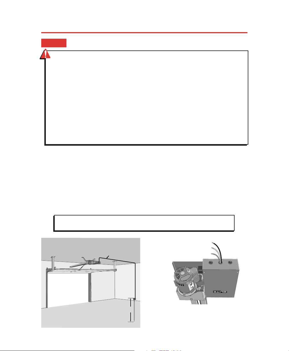
INSTALLATION OF OPERATOR
STEP 1
STEP 2
Make sure the hardware springs are balanced and the gate/door
opens and closes smoothly.
With the gate/door closed, mark the center of the gate/door.
Open the gate/door and mark the center point of the gate/door on the ceiling.
C
L
Gate
C
L
Door
Page 8
Door Arm
Gate Arm
C
L
C
L
C
L
Header Bracket
MOUNTING THE OPERATOR
Lift the operator and align with center mark on ceiling. Have someone hold the
operator in place or use something as a support post, and bolt to ceiling. (A support
post is not part of the operator. Use only for installation.)
Bolt or weld arm to gate/door.
STEP 3
STEP 4
STEP 5
Concrete
Anchor
1/2" x 3 1/2"
Support
Post
Make sure the header bracket is in the center of the opening. Bolt or weld the end of the
track (header bracket) to wall.
7
C
L
Header Bracket
C
L
Page 9
HOW TO CONNECT POWER (115VAC)
Proper grounding gives an electrical charge, such as from an electrical static discharge or a near lightning strike, a
path from which to dissipate its energy safely into the earth.
Without this path, the intense energy generated by lightning could be directed towards the operator. Although
nothing can absorb the tremendous power of a direct lightning strike, proper grounding can protect the operator
in most cases.
The ground wire must be a single, whole piece of wire. Never splice two wires for the ground wire. If you should
cut the ground wire too short, break it, or destroy its integrity, replace it with a single wire length.
Use the proper type earth ground rod for your local area. In certain circumstances, metal water pipes may be
allowed for grounding the operator. Check and follow all local codes for proper grounding procedures.
Black = 115 VAC Wire
White = Neutral Wire
Green = Earth Ground Wire
Minimum of
a 20-Amp
dedicated
circuit needed
for power.
Use UL listed
conduit to
enclose
power wires
Chamberlain Professional Products is not
responsible for improper installation or
failure to comply with all necessary local
building codes.
CAUTION: To avoid damaging gas, power, or other underground utility lines, contact
local underground utility locating companies before digging more than 18" deep.
STEP 6
Minimum 12 Gauge Ground
Wire connected to
HCT Earth Ground Wire
8 ft.
Earth Ground Rod
• Disconnect power at the fuse box BEFORE
proceeding. Operator MUST be properly
grounded and connected in accordance with
local electrical codes. NOTE: The operator
should be on a separate fused line of
adequate capacity.
• ALL electrical connections MUST be made by
a qualified individual.
• Do not install any wiring or attempt to run
the operator without consulting the wiring
diagram. We recommend that you install an
optional reversing edge BEFORE proceeding
with the control station installation.
• ALL power wiring should be on a dedicated
circuit and well protected. The location of the
power disconnect should be visible and
clearly labeled.
• ALL power and control wiring must be run in
separate conduit.
• BEFORE installing power wiring or control
stations, be sure to follow ALL specifications
and warnings described below. Failure to do
so may result in SEVERE INJURY to persons
and/or damage to operator.
• Entrapment protection devices MUST be
installed to protect anyone who may come
near a moving gate/door.
WARNING: To reduce the risk of SERIOUS INJURY or DEATH:
8
Page 10
9
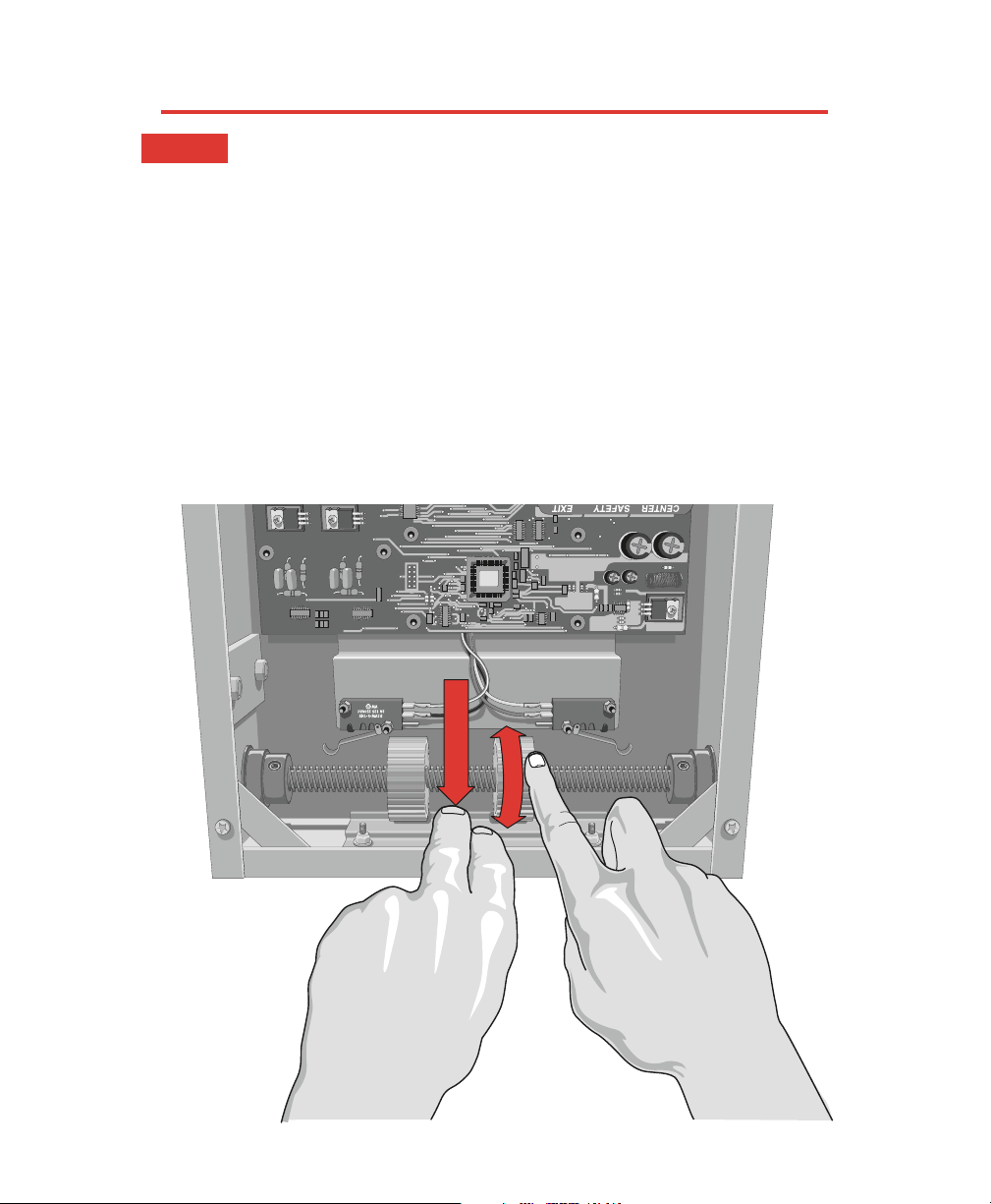
ADJUSTING TRAVELING DISTANCE
Before
Adjusting, Do the Following:
1. Turn the Power OFF!
2. Push the limit nut lock plate inward. Roll the nut to the direction desired.
3. Place the plate back in the notch.
4. Reapply power to operator.
5. If further adjustment is needed, repeat the process.
Push Plate
STEP 7
Page 11
10
2-WAY ADJUSTABLE REVERSING SENSOR
ADJUSTABLE TIMER
CENTER SAFETY EXIT
CENTER SAFETY EXIT
FIRE
DEPT.
13
STRIKE
OPEN
RADIO
RECEIVER
TIMER
SYSTEM ON
EXIT
LOOP
ALARM
SENSOR
REVERSE
SENSOR
OPEN
STOPCLOSE
SAFETY
LOOP
CENTER
LOOP
GATE
LOCKED
60
POWER
OVERLOAD
OFF
W4
OPEN LEFT
DC-BACKUP
ALARMSENSOR
OPEN RIGHT
3
SENSORS
RESET
MOTOR
13
13
COMMAND
PROCESSED
ON
GB
MS LINK
A
MADE IN USA
CENTER SAFETY EXIT
CENTER SAFETY EXIT
FIRE
DEPT.
13
STRIKE
OPEN
RADIO
RECEIVER
TIMER
SYSTEM ON
EXIT
LOOP
ALARM
SENSOR
REVERSE
SENSOR
OPEN
STOPCLOSE
SAFETY
LOOP
CENTER
LOOP
GATE
LOCKED
60
POWER
OVERLOAD
OFF
W4
OPEN LEFT
DC-BACKUP
ALARMSENSOR
OPEN RIGHT
3
SENSORS
RESET
MOTOR
13
13
COMMAND
PROCESSED
ON
GB
MS LINK
A
MADE IN USA
TIMERTIMER
NSOR
60
OFF
OPEN LEFT OPEN RIGHT
3
13
ONON
Timer ON
TIMERTIMER
NSOR
60
OFFOFF
OPEN LEFT OPEN RIGHT
3
13
ON
Timer OFF
Set Timer
1 to 60 seconds
Timer can be set from 1 to 60 seconds (Timer ON),
For push open/push close type operation (Timer OFF).
DO NOT TOUCH ALARM SENSOR
The level of reverse sensitivity has to do with the weight
of the gate and the condition of installation.
Too sensitive = If the gate stops or reverses by itself.
Not sensitive enough = If the gate hits an obstruction or
vehicle and does not stop or reverse.
NOTE: If the power supply to the gate operator is
less than 99 volts, adjust the alarm by turning the
alarm adjustment counter-clockwise enough to
actuate the alarm when obstructed but not sensitive
enough for false triggering to occur.
Adjusted by Qualified Service Personnel
3
REVERSEREVERSE
SENSORSENSOR
13
Maximum
Sensitivity
Minimum
Sensitivity
Gate ONLY
STEP 8
STEP 9
Page 12
11
Strike Open
Push Button
Strike Open
Push Button
24 Volts DC24 Volts DC
Fire Dept.
Key Switch
Fire Dept.
Key Switch
M/S LinkM/S Link
Class 2
Supply
Class 2
Supply
Center
Loop
Center
Loop
Safety
Loop
Safety
Loop
Radio
Receiver
Radio
Receiver
Exit
Loop
Exit
Loop
GG
BB
AA
––
++
OmniControl Surge Suppressor
P
/N
Q
4
1
0
P
a
te
n
t P
e
n
d
in
g
P
/N
Q
4
1
0
P
a
te
n
t P
e
n
d
in
g
®
Radio Power
Relay
24 Volt
3 Wire 24 VDC
Radio Receiver
4 Wire 24 VDC
Radio Receiver
External “Exit” Loop Detector
External “Safety” Loop Detector
Photo Beam
Phone
Entry
Push
Button
Card
Reader
Fire or
Any Key
Switch
4
7
8
0
H
E
L
P
9
1
2
3
5
6
++
––
Red 24 Volt
Grey
Black
Grey
7 1312111098
7
13
12
11
10
9
10
9
10
9
8
1 65
6
5
43
4
3
4
3
2
++
––
––
13
12
11
11
CENTER SAFETY EXIT
FIR
E
DEPT.
1
3
STRIKE
OPEN
RADIO
RECEIVER
TIM
ER
SYSTEM O
N
EXIT
LOOP
A
L
A
R
M
S
E
N
S
O
R
R
E
V
E
R
S
E
S
E
N
S
O
R
O
P
E
N
S
T
O
P
C
L
O
S
E
SAFETY
LO
OP
CENTER
LOOP
GATE
LO
CKED
60
POW
ER
OVER
LOAD
O
FF
W4
O
PEN LEFT
SEN
OPEN R
IGHT
3
SENS
ORS
RESET
M
OTO
R
1
3
1
3
C
O
M
M
A
N
D
P
R
O
C
E
S
S
E
D
ON
G
B
M
S
LIN
K
A
M
A
D
E
IN
U
S
A
Ground (-)
24 VDC (+)
Output Power
Important: Terminals 11 and 12 are the only terminals
that will Open and Close with a single push of a button. All
other terminals will only open with a single push of a button.
Wire
Removable
Terminal
Connectors
Master/Second Link:
Not used in normal
installation
TERMINAL INPUT CONNECTIONS
STEP 10
WARNING: To ENSURE proper operation
of safety devices:
• ENSURE bare wire makes good contact
inside removable terminal connectors.
• DO NOT let wire insulation interfere with
connection.
Page 13

12
IMPORTANT INFORMATION
CENTER SAFETY EXIT
CENTER SAFETY EXIT
FIRE
DEPT.
13
STRIKE
OPEN
RADIO
RECEIVER
TIMER
SYSTEM ON
EXIT
LOOP
ALARM
SENSOR
REVERSE
SENSOR
OPEN
STOPCLOSE
SAFETY
LOOP
CENTER
LOOP
GATE
LOCKED
60
POWER
OVERLOAD
OFF
W4
OPEN LEFT
DC-BACKUP
ALARMSENSOR
OPEN RIGHT
3
SENSORS
RESET
MOTOR
13
13
COMMAND
PROCESSED
ON
GB
MS LINK
A
MADE IN USA
Make sure the system is “OPEN TO LEFT”
RADIO
MER
60
OFF
13
ON
OPEN LEFT
OPEN RIGHT
Installers are required to adhere to this procedure: The UL required Warning Signs must be installed
in plain view and on
both sides
of each commercial gate installed. Each sign is made with fastening
holes in each corner and should be permanently secured in a suitable manner. Also the warning
sticker should be placed on the operator so it is clearly visible.
STEP 11
STEP 12
Page 14
Relay Contact Rating
0.5 Amp - 125 VAC
1 Amp - 24 VDC
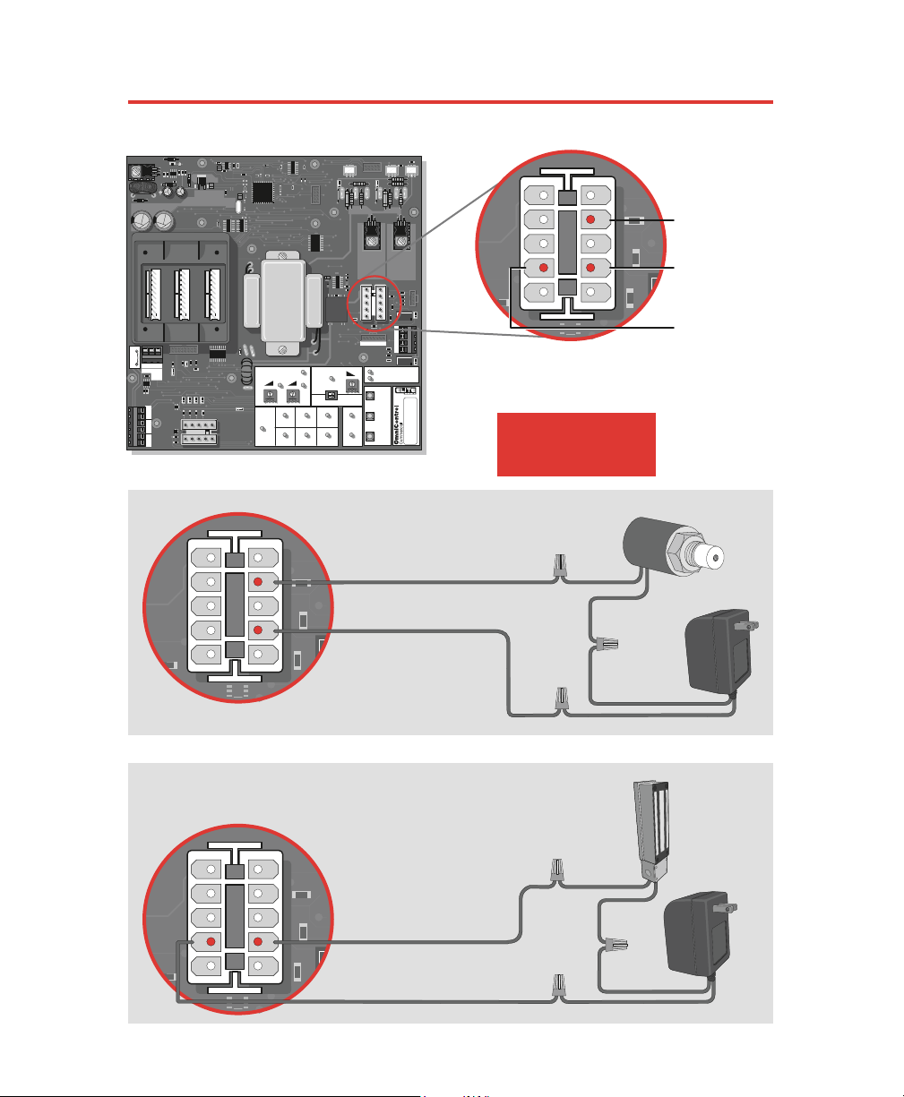
SOLENOID/MAGLOCK J3 CONNECTION
CENTER SAFETY EXIT
CENTER SAFETY EXIT
FIRE
DEPT.
13
STRIKE
OPEN
RADIO
RECEIVER
TIMER
SYSTEM ON
EXIT
LOOP
ALARM
SENSOR
REVERSE
SENSOR
OPEN
STOPCLOSE
SAFETY
LOOP
CENTER
LOOP
GATE
LOCKED
60
POWER
OVERLOAD
OFF
W4
OPEN LEFT
DC-BACKUP
ALARMSENSOR
OPEN RIGHT
3
SENSORS
RESET
MOTOR
13
13
COMMAND
PROCESSED
ON
GB
MS LINK
A
MADE IN USA
Connection of a Solenoid or Magnetic Lock can be made
using the J3 plug and three wires provided with the unit.
J3J3
Normally Closed
Normally Open
Common
9
7
1
3
5
2
8
6
4
10
J3J3
9
7
1
3
5
2
8
6
4
10
J3J3
9
7
1
3
5
2
8
6
4
10
Insert 2 provided wires
into J3 plug (#3 and #7)
(Motor Harness)
#3 Normally Closed
#7 Common
Plug-In
Transformer
Solenoid Lock
Solenoid Lock
Ground
Ground
Power
Wire Nut
Magnetic Lock
Insert 2 provided wires
into J3 plug (#7 and #8)
(Motor Harness)
#7 Common
#8 Normally Open
Plug-In
Transformer
Magnetic
Lock
Ground
Ground
Power
Wire Nut
Gate ONLY
13
Page 15

14
THREE PUSH BUTTON SYSTEM
(OPEN-STOP-CLOSE)
Step 1 - Cut jumper wire #W4.
Step 2 - Install Omni option board.
Step 3 - Connect OPEN push button to # 1 .
Step 4 - Connect STOP push button to # 3 .
Step 5 - Connect CLOSE push button to # 5 & 6 .
CENTER SAFETY EXIT
CENTER SAFETY EXIT
FIRE
DEPT.
13
STRIKE
OPEN
RADIO
RECEIVER
TIMER
SYSTEM ON
EXIT
LOOP
ALARM
SENSOR
REVERSE
SENSOR
OPEN
STOPCLOSE
SAFETY
LOOP
CENTER
LOOP
GATE
LOCKED
60
POWER
OVERLOAD
OFF
W4
OPEN LEFT
DC-BACKUP
ALARMSENSOR
OPEN RIGHT
3
SENSORS
RESET
MOTOR
13
13
COMMAND
PROCESSED
ON
GB
MS LINK
A
MADE IN USA
QCC
AB
OPEN STOP CLOSE MAGLOCK ALARM
ARMED
M/S LINK
QCC
AB
OPEN STOP CLOSE MAGLOCK ALARM
ARMED
M/S LINK
2 3 4 5 6 7 8 9 10 11 12 13 14 151
351
16
QCC socket with QCC access ID inserted
QCC “Mode of Operation” switch
Omni Option Board
Part # OMNIEXB
– Open Command
– Stop Command
– Close Command
– Common
– Normally Closed
– Normally Open
Maglock
Master/Second
RS485
– Burglar Alarm Output
– Burglar Alarm Input
– Ground
– B
– A
10
& 11
12
& 13
14
15
16
Solenoid
Gnd
Gnd
Gnd
Gnd
Gnd
B
A
N.O.
N.O.
N.O.
N.O.
N.C.
N.C.
N.C.
Com
Com
QCC is designed for slide gate operators only!
THREE PUSH BUTTON SYSTEM
INSTRUCTIONS FOR OPTIONAL SYSTEMS
CENTER SAFETY EXIT
CENTER SAFETY EXIT
FIRE
DEPT.
13
STRIKE
OPEN
RADIO
RECEIVER
TIMER
SYSTEM ON
EXIT
LOOP
ALARM
SENSOR
REVERSE
SENSOR
OPEN
STOPCLOSE
SAFETY
LOOP
CENTER
LOOP
GATE
LOCKED
60
POWER
OVERLOAD
OFF
W4
OPEN LEFT
DC-BACKUP
ALARMSENSOR
OPEN RIGHT
3
SENSORS
RESET
MOTOR
13
13
COMMAND
PROCESSED
ON
GB
MS LINK
A
MADE IN USA
QCC
AB
OPEN STOP CLOSE MAGLOCK ALARM
ARMED
M/S LINK
OPENOPEN STOPSTOP CLOSECLOSE
W4
Omni “Option Board” Needed to Perform This Function
Note: If using the Master/Second board
configuration, unplug the Master/Second
link plug on main board and connect it into
the Omni option board M/S link socket.
Make sure each push button is dry contact
and there are no jumper wires between
them.
IMPORTANT! The Stop button must be “Normally Closed.”
2, 4 and 6 are common on Omni Option board for a 4 wire installation.
N.O.
N.O.
Com
N.C.
1 & 2
3
& 4
5
& 6
7
8
9
642
Page 16

15
ALARM/PROXIMITY SWITCH CONNECTIONS
CENTER SAFETY EXIT
CENTER SAFETY EXIT
FIRE
DEPT.
13
STRIKE
OPEN
RADIO
RECEIVER
TIMER
SYSTEM ON
EXIT
LOOP
ALARM
SENSOR
REVERSE
SENSOR
OPEN
STOPCLOSE
SAFETY
LOOP
CENTER
LOOP
GATE
LOCKED
60
POWER
OVERLOAD
OFF
W4
OPEN LEFT
DC-BACKUP
ALARMSENSOR
OPEN RIGHT
3
SENSORS
RESET
MOTOR
13
13
COMMAND
PROCESSED
ON
GB
MS LINK
A
MADE IN USA
Omni Option Board
Part # OMNIEXB
Proximity Switch
Part # APRS
12VDC
Alarm System
Dry Contact
Use Low Voltage
Wire 20 AWG
QCC
AB
OPEN STOP CLOSE MAGLOCK ALARM
ARMED
M/S LINK
10 11 12 13
QCC
AB
OPEN STOP CLOSE MAGLOCK ALARM
ARMED
M/S LINK
Omni “Option Board” Needed to Perform This Function
Alarm
10 – Common
11 – Normally Open
Armed
12 – Normally Closed
13 – Ground
2"
Max.
2"
Max.
Page 17

16
CENTER SAFETY EXIT
CENTER SAFETY EXIT
FIRE
DEPT.
13
STRIKE
OPEN
RADIO
RECEIVER
TIMER
SYSTEM ON
EXIT
LOOP
ALARM
SENSOR
REVERSE
SENSOR
OPEN
STOPCLOSE
SAFETY
LOOP
CENTER
LOOP
GATE
LOCKED
60
POWER
OVERLOAD
OFF
W4
OPEN LEFT
DC-BACKUP
ALARMSENSOR
OPEN RIGHT
3
SENSORS
RESET
MOTOR
13
13
COMMAND
PROCESSED
ON
GB
MS LINK
A
MADE IN USA
QCC
AB
OPEN STOP CLOSE MAGLOCK ALARM
ARMED
M/S LINK
CENTER SAFETY EXIT
CENTER SAFETY EXIT
FIRE
DEPT.
13
STRIKE
OPEN
RADIO
RECEIVER
TIMER
SYSTEM ON
EXIT
LOOP
ALARM
SENSOR
REVERSE
SENSOR
OPEN
STOPCLOSE
SAFETY
LOOP
CENTER
LOOP
GATE
LOCKED
60
POWER
OVERLOAD
OFF
W4
OPEN LEFT
DC-BACKUP
ALARMSENSOR
OPEN RIGHT
3
SENSORS
RESET
MOTOR
13
13
COMMAND
PROCESSED
ON
GB
MS LINK
A
MADE IN USA
QCC
AB
OPEN STOP CLOSE MAGLOCK ALARM
ARMED
M/S LINK
SOLENOID CONNECTION WITH OMNI OPTION BOARD
MAGLOCK CONNECTION WITH OMNI OPTION BOARD
Omni “Option Board” Needed to Perform This Function
Omni “Option Board” Needed to Perform This Function
SE MAGLOCKMAGLOCK AL
Plug-In
Transformer
Solenoid Lock
Ground
Ground
Power
Wire Nut
9
Omni Option Board
Part # OMNIEXB
7 – Common
8 – Normally Closed
9 – Normally Open
7 – Common
8 – Normally Closed
9 – Normally Open
SE MAGLOCKMAGLOCK AL
Plug-In
Transformer
Magnetic
Lock
Ground
Ground
Power
Wire Nut
8
Omni Option Board
Part # OMNIEXB
Relay Contact Rating
0.5 Amp - 125 VAC
1 Amp - 24 VDC
Relay Contact Rating
0.5 Amp - 125 VAC
1 Amp - 24 VDC
7
7 9
8
Gate ONLY
Page 18

17
CENTER SAFETY EXIT
CENTER SAFETY EXIT
FIRE
DEPT.
13
STRIKE
OPEN
RADIO
RECEIVER
TIMER
SYSTEM ON
EXIT
LOOP
ALARM
SENSOR
REVERSE
SENSOR
OPEN
STOPCLOSE
SAFETY
LOOP
CENTER
LOOP
GATE
LOCKED
60
POWER
OVERLOAD
OFF
W4
OPEN LEFT
DC-BACKUP
ALARMSENSOR
OPEN RIGHT
3
SENSORS
RESET
MOTOR
13
13
COMMAND
PROCESSED
ON
GB
MS LINK
A
MADE IN USA
STOP BUTTON ALARM SHUT OFF
QCC
AB
OPEN STOP CLOSE MAGLOCK ALARM
ARMED
M/S LINK
OPEN STOPSTO P CLOSE
Stop
Button
N.C.
Com
W4
Omni “Option Board” Needed to Perform This Function
Cut jumper wire #W4.
Install the stop
button in a secure
accessible place.
This is an important command required to stop the audio alarm in case it has
been triggered. Otherwise the alarm will sound for 5 minutes and reset itself.
• To stop the movement of the operator in case of potential entrapment.
• To reset the audio alarm. (Check for obstructions!)
• To stop the operator while traveling.
Use STOP Button:
QCC
AB
OPEN STOP CLOSE MAGLOCK ALARM
ARMED
M/S LINK
3 4
12 56
Omni Option Board
Part # OMNIEXB
When using the
Omni option board,
use the “STOP”
input to connect the
stop button.
Page 19

18
OPTIONAL RELAY ADAPTER CONNECTION
CENTER SAFETY EXIT
CENTER SAFETY EXIT
FIRE
DEPT.
13
STRIKE
OPEN
RADIO
RECEIVER
TIMER
SYSTEM ON
EXIT
LOOP
ALARM
SENSOR
REVERSE
SENSOR
OPEN
STOPCLOSE
SAFETY
LOOP
CENTER
LOOP
GATE
LOCKED
60
POWER
OVERLOAD
OFF
W4
OPEN LEFT
DC-BACKUP
ALARMSENSOR
OPEN RIGHT
3
SENSORS
RESET
MOTOR
13
13
COMMAND
PROCESSED
ON
GB
MS LINK
A
MADE IN USA
Connection of a Solenoid or Magnetic Lock can be made
using the “Optional” Relay Adapter Module.
Relay Contact Rating
2 Amp - 125 AC/DC
2 Amp switching load capability
Normally Closed
Normally Open
Optional Relay Adapter Module
Optional Relay Adapter Module
Common
Common
Plug-In
Transformer
Solenoid Lock
Solenoid Lock
Ground
To OmniControl Board
To OmniControl Board
Ground
Power
Magnetic Lock
Plug-In
Transformer
Magnetic
Lock
Ground
Ground
Power
Relay Light On: Indicates
actuation of OmniControl board
Relay Module LEDs
Part # Q400MAU
Power Light On: Indicates
power is being received
Gate ONLY
Page 20

19
CENTER SAFETY EXIT
CENTER SAFETY EXIT
FIRE
DEPT.
13
STRIKE
OPEN
RADIO
RECEIVER
TIMER
SYSTEM ON
EXIT
LOOP
ALARM
SENSOR
REVERSE
SENSOR
OPEN
STOPCLOSE
SAFETY
LOOP
CENTER
LOOP
GATE
LOCKED
60
POWER
OVERLOAD
OFF
W4
OPEN LEFT
DC-BACKUP
ALARMSENSOR
OPEN RIGHT
3
SENSORS
RESET
MOTOR
13
13
COMMAND
PROCESSED
ON
GB
MS LINK
A
MADE IN USA
UL Listed Edge Sensor
(3-Sided Activation)
Edge Sensor Wiring
If you are going to use a contact sensor as a secondary entrapment protection you should use a
recognized component to comply with the revised UL325 intended to be used in class I or class II
gate operator.
Note: If multiple sensors are being used, all of the edge sensors are to
be connected in parallel at the sensor input on the Omni Control board.
SECONDARY ENTRAPMENT PROTECTION
Secondary Entrapment Protection (Contact Sensor)
When touched, the electrically activated edge sensors
immediately signal the door/gate operator to stop and reverse.
Property owners are obligated to test edges regularly.
OmniControl
Board
P
ALARMSENSOR
UL Listed Edge Sensor
(3-Sided Activation)
Important: DO NOT remove any existing
attached wires from the Sensor/Alarm connector.
Page 21

20
SECONDARY ENTRAPMENT PROTECTION
Mount to Wall
or Floor
2 Wires to Operator
OmniControl Board and
Electronic Box Terminals
(See next page for wiring)
Conduit
Secondary Entrapment Protection (Non-Contact Sensor)
Mount Photo Beam Sensor at Recommended
Height and Align Properly
Mount Photo Beam Sensor
at Recommended Height
and Align Properly
Page 22

21
OffOf
f
OffOf
f
OnOn
OnOn
OnOn
OffOff
OffO
f
f
OffOf
f
OnOn
OffOff
Off
Ga
t
e
Oper
a
t
o
r
Mai
n
Roo
m
Eug. Rm
Oper. Rm
Eug. Dept.
Manu. 1 Rm
Main
Dept.
M
a
nu
.
2 Rm
A
ir (1
)
Co
n
d
itio
n
e
r
Air (2)
Conditioner
Conference
Room 1
C
o
n
f
e
r
e
n
c
e
R
m
2
,
3
R
ef
er
.
Bus
1, 2, 3
C
o
n
fe
r
e
n
c
e
Ro
o
m
2
C
o
m
p
.
S
er
v
e
2
C
o
m
p
.
S
e
r
ve
1
CENTER SAFETY EXIT
CENTER SAFETY EXIT
FIRE
DEPT.
13
STRIKE
OPEN
RADIO
RECEIVER
TIMER
SYSTEM ON
EXIT
LOOP
ALARM
SENSOR
REVERSE
SENSOR
OPEN
STOPCLOSE
SAFETY
LOOP
CENTER
LOOP
GATE
LOCKED
60
POWER
OVERLOAD
OFF
W4
OPEN LEFT
DC-BACKUP
ALARMSENSOR
OPEN RIGHT
3
SENSORS
RESET
MOTOR
13
13
COMMAND
PROCESSED
ON
GB
MS LINK
A
MADE IN USA
Wire-Loop “Exit Loop”
Wire-Loop “Safety Loop”
CAUTION: Use different frequencies for
every single loop detector. Turn off
operator power (breaker switch from
main power source) before installation.
Twisted wires must be 6 turns per foot “Minimum”
OPTIONAL PLUG-IN LOOP DETECTORS
Plug-In Loop detectors needed to perform
this function. Part # AELD
S
tr
ik
e
O
p
e
n
P
u
s
h
B
u
tto
n
S
tr
ik
e
O
p
e
n
P
u
s
h
B
u
tto
n
2
4
V
o
l
t
s
D
C
2
4
V
o
l
t
s
D
C
F
ire
D
e
p
t
K
e
y
S
w
it
c
h
F
ire
D
e
p
t
K
e
y
S
w
it
c
h
M
/
S
L
i
n
k
M
/
S
L
i
n
k
Class 2
Supply
Class 2
Supply
C
e
n
te
r
L
o
o
p
C
e
n
te
r
L
o
o
p
S
a
fe
ty
L
o
o
p
S
a
fe
ty
L
o
o
p
R
a
d
io
R
e
c
e
iv
e
r
R
a
d
io
R
e
c
e
iv
e
r
E
x
it
L
o
o
p
E
x
it
L
o
o
p
GG
BB
AA
––
++
Om
niControl Surge Suppressor
P
/N
Q
410
Patent Pen
din
g
P
/N
Q
410
Patent Pen
din
g
®
SECONDARY ENTRAPMENT PROTECTION
Photo Beam Wiring
Surge Suppressor
Terminal Wiring
CENTER SAFETY EXIT
CENTER SAFETY EXIT
FIRE
DEPT.
13
STRIKE
OPEN
RADIO
RECEIVER
TIMER
SYSTEM ON
EXIT
LOOP
ALARM
SENSOR
REVERSE
SENSOR
OPEN
STOPCLOSE
SAFETY
LOOP
CENTER
LOOP
GATE
LOCKED
60
POWER
OVERLOAD
OFF
W4
OPEN LEFT
DC-BACKUP
ALARMSENSOR
OPEN RIGHT
3
SENSORS
RESET
MOTOR
13
13
COMMAND
PROCESSED
ON
GB
MS LINK
A
MADE IN USA
P
ALARMSENSOR
If multiple sensors are
being used, all of the
photo beam sensors are
to be connected in
parallel at the sensor
input on the OmniControl
board.
If you are going to use a non-contact sensor as a secondary entrapment protection you should use a
recognized component to comply with the revised UL325 intended to be used in class I or class II gate
operator, like the following:
Part # CPS/CPS-N4
Radio Rec +
Radio Rec
-
13
11
Page 23

22
HCT LOOP SIZE AND PLACEMENT
It is VERY important to have enough separation between loops and gate to prevent false detection.
If A =
Then C =
6 Feet
4 Feet
9 Feet
4.5 Feet
12 Feet
5 Feet
15 Feet
5 Feet
18 Feet
5.5 Feet
21 Feet
6 Feet
This is for a typical HCT loop installation. Individual circumstances may alter dimensions.
For toll free technical support: 1-800-528-2806
As A increases in size to cover a larger opening, the gate will cause a larger change of inductance when opening
and closing. Therefore dimension C must increase as A increases.
If the Inside and outside safety loop are connected to the same loop detector they should be series connected.
Dimension
A, B and C should be the same for each loop. Both loops should have the same number of wire turns.
(See Page 23)
Dimension
D should be equal to or greater than the larger of the “Inside Safety Loop” or “Exit Loop’s”
dimension B.
Out
In
Inside
Safety
Loop
Outside
Safety
Loop
Exit
Loop
A
B
BB
CCD
Drawing not to scale
4 Feet
Page 24

Loop Installation “Saw Cut” Type
LOOP INSTALLATION AND NUMBER OF WIRE TURNS
Mark the loop layout on the pavement. Remove sharp inside corners that can damage the loop wire
insulation.
Set the saw to cut to a depth (typically 2" to 2.5") that insures a minimum of 1" from the top of the wire to
pavement surface. The saw cut width should be larger than the wire diameter to avoid damage to the wire
insulation when placed in the saw slot. Cut the loop and feeder slots. Remove all debris from the slot with
compressed air. Check that the bottom of the slot is even.
It is highly recommended that a continuous length of wire be used to form the loop and feeder to the
detector. It is also highly recommend using 12-18 AWG cross-link polyethylene (XLPE) insulation for the
loop wire. Use heavier wire gauge for a more durable loop area. Use a wood stick or roller to insert the wire
to the bottom of the saw cut (Do not use sharp objects). Wrap the wire in the loop saw cut until the desired
number of turns is reached. Each turn of wire must lay flat on top of the previous turn.
The wire must be twisted together a minimum of 6 twists per foot from the end of the saw cut to the
detector.
The wire must be held firmly in the slot with 1" pieces of backer rod every 1 to 2 feet. This prevents the wire
from floating when the loop sealant is applied.
Apply a sealant. The sealant selected should have good adhering properties with similar expansion and
contraction characteristics to that of the pavement material.
Number of Wire Turns Needed for Loop
1
2
2
3
4
5
6
6
5
10 feet to 13 feet
14 feet to 26 feet
27 feet to 80 feet
80 feet and up
Loop Perimeter
Important!
Number of Wire Turns
4
3
2
1
The wire is continuously wound
in the loop saw cut for the
required number of turns. One
turn shown. (Refer to table)
The wire must be twisted together 6 twists per foot
from the end of the saw cut to the loop detector.
Remove sharp inside corners
by making corner cuts
Saw Cut
Home Run
Feeder Slot
Sealant
Backer Rod
Insulated Loop Wire
3 turns Shown, amount varies.
Refer to table
Recommended Loop Wire
G50XNL1818
G50XNL1218
Min 1"
1/8" to 1/4" Width,
2" to 2.5" Depth Saw Cut
Pavement Material
1
2
3
3
Loop Cut
Continuous 3 turns of wire
shown (Refer to table)
5
23
Page 25

24
Strike O
pen
Push Button
Strike O
pen
Push Button
24 Volts DC24 Volts DC
Fire D
e
pt
Key S
w
itch
Fire D
e
pt
Key S
w
itch
M/S LinkM/S Link
Class 2
Supply
Class 2
Supply
Center
Loop
Center
Loop
S
afety
Loop
S
afety
Loop
R
adio
R
eceiver
R
adio
R
eceiver
Exit
Loop
Exit
Loop
GG
BB
AA
––
++
OmniControl S
ur
ge S
uppressor
P
/N
Q
4
1
0
P
a
te
n
t P
en
d
in
g
P
/N
Q
4
1
0
P
a
te
n
t P
en
d
in
g
®
7 1312111098
1 65432
WIRING EXTERNAL LOOP DETECTORS
External 115 VAC “Exit” Loop Detector -
Allows operator to automatically open for
exiting vehicles.
6
5
3
4
External 115 VAC “Safety” Loop Detector -
Allows system to stay open when vehicles are
obstructing path.
Caution:
To PREVENT damage to vehicles
shorter than 14 feet, a center loop system should
be installed.
If
the
“Inside”
and
“Outside”
safety loops are
connected to the
same
loop detector:
• They should be series connected to the detector
• Have the same dimensions. (Page 22)
• Have the same number of wire turns. (Page 23)
Note:
External 115 VAC Loop Detectors
For installation information about Plug-In Loop detectors, please refer to page 23.
O
UT
Saf
ety
L
o
op
Ex
it
Loop
I
N
Safety
L
oo
p
O
UT
S
a
f
e
ty
L
o
op
Exi
t
Loo
p
IN
S
af
e
ty
L
oo
p
Page 26

25
SET SECURITY MODE
The Universal Receiver can be used with up to
15 rolling code remotes or passwords in HIGH
security mode. Alternately, it can be used with
up to 31 of any type remote in NORMAL
security mode, including any combination of
rolling code, billion code, or dip switch remotes.
The jumper must be set at the HIGH position for
the receiver to operate in HIGH security mode.
It must be set at NORMAL position to operate at
the NORMAL mode.
When changing from NORMAL to HIGH security
mode, any previous remote codes must be
erased. Repeat Steps 2 and 3 in the
Programming Section on the next page to
reprogram the receiver for each remote control in
use.
The receiver is factory set at HIGH. To verify
frequency, please refer to the label on the unit.
PROGRAMMING THE RADIO RECEIVER
WARNING: To reduce the risk of
SERIOUS INJURY or DEATH from
electrocution:
• Be sure power is not connected BEFORE
installing the receiver.
To reduce the risk of SERIOUS INJURY or
DEATH from a moving gate or garage
door:
• ALWAYS keep remote controls out of
reach of children. NEVER permit children
to operate, or play with remote control.
• Activate gate or door ONLY when it can
be seen clearly, is properly adjusted, and
there are no obstructions to door travel.
• ALWAYS keep gate or garage door in
sight until completely closed. NEVER
permit anyone to cross path of moving
gate or door.
NOTICE: To comply with FCC and or Industry Canada (IC) rules, adjustment or modifications of this
receiver and/or transmitter are prohibited, except for changing the code setting or replacing the
battery. THERE ARE NO OTHER USER SERVICEABLE PARTS.
Tested to Comply with FCC Standards for home or office use. Operation is subject to the following two
conditions: (1) this device may not cause harmful interference, and (2) this device must accept any
interference received, including interference that may cause undesired operation.
HIGH SECURITY MODE
NORMAL SECURITY MODE
Security Mode
Terminals
Jumper
Security Mode
Terminals
Jumper
Page 27

26
SET OUTPUT DURATION
For commercial applications, the receiver can be set for either constant or momentary closure on the
output contacts. Use of constant closure is prohibited on residential garage door openers because it
overrides the safety reversal devices.
With the jumper in the “M” (Momentary) position, the contacts will close for 1/4 second regardless of
the length of radio transmission. With the jumper in “C” (Constant) position, the contacts will stay
closed as long as the radio continues transmitting.
The receiver is factory set at M.
PROGRAMMING THE REMOTE TO THE RECEIVER
1. Pry open the front panel of
receiver case with a coin or a
screwdriver. Re-connect
power to opener.
2. Press and release the
“learn” button on the receiver.
The learn indicator light will
glow steadily for 30 seconds.
3. Within 30 seconds, press and hold the button
on the hand-held remote that you wish to
operate your operator.
The opener will now operate when the push
button on either the receiver or the remote
control is pressed.
Repeat Steps 2 and 3 for each remote control
that will be used to operate the opener.
WARNING: To reduce the risk of SERIOUS INJURY or DEATH, the
use of CONSTANT OPERATION on residential openers is PROHIBITED.
OPENING RECEIVER
Connect
Antenna
Output
Duration
Terminals
Jumper
M
CONSTANT
OPERATION
Output
Duration
Terminals
Jumper
M
MOMENTARY
OPERATION
TO ERASE ALL REMOTE CONTROL CODES
Press and hold the “learn” button on the
receiver panel until the indicator light turns off
(about 6 seconds). All remote codes are now
erased. Then follow the programming steps to
reprogram each remote control.
Learn Button
Indicator Light
Output
Duration
Terminals
Security
Mode
Power
Supply
Jumper
OPEN RECEIVER
24V
12V
HIGH
NORM
C
P2
M
PROGRAMMING THE RADIO RECEIVER
Page 28

27
HOW TO REPLACE THE CONTROL BOARD
AUDIO ALARM
When one of the following events happens
Twice Consecutively, an Alarm will Sound!
Check for broken
spring or hardware
Ensure dolly is not
hitting the chassis
or an unwanted
Check for broken wheel or
damaged track
Gate/door hits obstruction.
S
tr
ik
e
O
p
en
P
u
sh
B
u
tton
S
tr
ik
e
O
p
en
P
u
sh
B
u
tton
24
Vo
lts
DC
24
Vo
lts
DC
F
ire
D
e
pt
.
Key
Swi
tch
F
ire
D
e
pt
.
Key
Swi
tch
M
/
S
Li
nk
M
/
S
Li
nk
Cl
a
ss
2
Supply
Cl
a
ss
2
Supply
C
e
n
te
r
Loo
p
C
e
n
te
r
Loo
p
S
a
f
ety
L
o
o
p
S
a
f
ety
L
o
o
p
Rad
i
o
Re
c
e
iv
e
r
Rad
i
o
Re
c
e
iv
e
r
Ex
it
Loo
p
Ex
it
Loo
p
GG
BB
AA
––
++
OmniControl
S
u
rge
Su
pp
res
sor
P
/
N Q41
0
P
a
t
e
nt P
e
n
d
i
n
g
P
/
N Q41
0
P
a
t
e
nt P
e
n
d
i
n
g
®
Disconnect wire harnesses from OmniControl board. Unscrew 3 nuts and remove board.
Strike Open
Pu
sh
Bu
t
ton
Strike Open
Pu
sh
Bu
t
ton
24
V
ol
ts
DC
24
V
ol
ts
DC
F
ire
D
e
pt.
Ke
y S
w
it
c
h
F
ire
D
e
pt.
Ke
y S
w
it
c
h
M/
S
L
i
n
k
M/
S
L
i
n
k
Cl
a
s
s
2
S
u
p
p
l
y
Cl
a
s
s
2
S
u
p
p
l
y
C
e
nt
e
r
L
o
op
C
e
nt
e
r
L
o
op
S
a
f
e
t
y
L
o
o
p
S
a
f
e
t
y
L
o
o
p
Ra
di
o
Receiv
e
r
Ra
di
o
Receiv
e
r
E
x
i
t
L
o
o
p
E
x
i
t
L
o
o
p
GG
BB
AA
––
++
Omn
iC
on
t
ro
l
S
u
rg
e S
u
p
p
re
ss
or
P
/
N
Q
410
P
a
t
e
nt P
e
nd
i
ng
P
/
N
Q
410
P
a
t
e
nt P
e
nd
i
ng
®
WARNING:
To reduce the risk of SERIOUS INJURY or DEATH,
the alarm MUST NOT be disabled.
Page 29

28
IMPORTANT SAFETY INSTRUCTIONS
READ AND FOLLOW ALL INSTRUCTIONS.
NEVER let children operate or play with gate controls. Keep the
remote control away from children.
ALWAYS keep people and objects away from the gate.
No one should cross the path of the moving gate.
Test the gate operator monthly. The gate MUST reverse on contact
with a rigid object or stop when an object activates the non-contact
sensors. After adjusting the force or the limit of travel, retest the
gate operator. Failure to adjust and retest the gate operator
properly can increase the risk of INJURY or DEATH.
Use the emergency release ONLY when the gate is not moving.
Make sure the power for the gate operator is off.
Keep gates properly maintained. Read the manual. Have a qualified
service technician make repairs to the gate or gate hardware.
The entrance is for vehicles ONLY. Pedestrians MUST use separate
entrance.
SAVE THESE INSTRUCTIONS.
1)
2)
3)
4)
5)
6)
7)
8)
WARNING: To reduce the risk of SERIOUS INJURY or DEATH:
Page 30

29
Lift the gate/door up.
When power is restored, the gate/door will automatically be operational.
Lift the gate/door up until fully open.
STEP 3 STEP 4
STEP 1 STEP 2
Insert key and turn to unlock position. Pull down the release ring.
MANUAL RELEASE
WARNING:
To reduce the risk of SERIOUS INJURY or DEATH from a
falling gate/door:
• If possible, use manual release to disengage trolley ONLY when door
is CLOSED. Weak or broken springs or unbalanced gate/door could
result in an open gate/door falling rapidly and/or unexpectedly.
• NEVER use emergency release unless gateway/doorway is clear of
persons and obstructions.
Page 31

30
TROUBLESHOOTING TABLE
Condition Possible Causes Solution
Overload LED ON
and
Power LED OFF
Overload LED On
and
Power LED On
System On LED
Flashing
Reverse Sensor LED On
Alarm Sensor LED On
Audio Alarm On
Command Processed
LED On
Timer LED Blinking and
Command Processed
LED Blinking
Timer LED Blinking,
Command Processed LED
Blinking and Reverse
Sensor LED On
Any “Loop LED” On and
No Vehicle on the
Sensing Area
1.
Short circuit at terminals 11 and 13
2.
Short circuit at any of the loop detector
in the board
3.
Short circuit in the control board
1.
Remove the short circuit condition at the
terminals
2.
Remove the defective loop detector
3.
Send the board to repair
1.
Excessive current draw at terminal 13
2.
Over-voltage at the 120 VAC line input
1.
Reduce the accessories load from surge
suppressor terminal 13
2.
Verify your electrical power
1.
One limit switch is faulty (Rapid Flashing)
2.
Motor thermal fuse has popped-out
(Slowly Flashing)
1.
Test the limit switches and wire connections,
fix the fault
2.
Reset the motor
1.
The loop detector needs to be reset.
2.
The wire loop has been disrupted
3.
The loop detector needs to work in a
different frequency
4.
The loop detector is too sensitive
1.
Reset the loop detector (If you use Plug-in
Loop detectors, change the setting for
sensitivity and come back to your original
setting).
2.
Verify and correct connections
3.
Set a different working frequency
4.
Decrease the sensitivity of the loop detector
1.
Gate/door has encountered an obstruction
during traveling
2.
Reverse sensor is extra sensitive
1.
Remove the obstruction
2.
Turn the reverse sensor switch counter
clockwise a little more and try again
1.
Gate/door encountered an obstruction
during traveling
2.
Alarm sensor is extra sensitive
1.
Remove the obstruction
2.
Turn the alarm sensor switch counter
clockwise a little more and try again
1.
There is a command hold active
1.
This is a normal response of the gate/door
operator. It does not represent necessarily
that there is a problem.
1.
There is a command holding the
gate/door open
1.
This is a normal response of the gate/door
operator. It does not represent necessarily
that there is a problem. Check inputs for
command.
1.
Gate/door has reopened because it
encountered an obstruction while closing.
1.
Any re-new command will resume normal
operation. Check for obstructions.
1.
Gate/door has encountered two
consecutive obstructions while trying
to close or open
1.
Any re-new command will resume normal
operation but not a radio command. Check
for obstructions.
2.
You can stop the alarm by using the stop
button.
For Toll Free Technical Support: 1-800-528-2806
Page 32

31
CENTER SAFETY EXIT
CENTER SAFETY EXIT
FIRE
DEPT.
13
STRIKE
OPEN
TIMER
SYSTEM ON
EXIT
LOOP
ALARM
SENSOR
REVERSE
SENSOR
OPEN
STOPCLOSE
SAFETY
LOOP
CENTER
LOOP
GATE
LOCKED
60
POWER
OVERLOAD
OFF
W4
OPEN LEFT
DC-BACKUP
ALARMSENSOR
OPEN RIGHT
3
SENSORS
13
13
COMMAND
PROCESSED
ON
GB
MS LINK
A
MADE IN USA
RESET
MOTOR
RADIO
RECEIVER
CENTER SAFETY EXIT
FIRE
DEPT.
13
STRIKE
OPEN
TIMER
SYSTEM ON
EXIT
LOOP
ALARM
SENSOR
REVERSE
SENSOR
OPEN
STOPCLOSE
SAFETY
LOOP
CENTER
LOOP
GATE
LOCKED
60
POWER
OVERLOAD
OFF
OPEN LEFT
DC-BACKUP
ALARMSENSOR
OPEN RIGHT
3
SENSORS
13
13
COMMAND
PROCESSED
ON
GB
MS LINK
A
MADE IN USA
RESET
MOTOR
RADIO
RECEIVER
TROUBLESHOOTING LED INFORMATION
CENTER SAFETY EXIT
CENTER SAFETY EXIT
FIRE
DEPT.
13
STRIKE
OPEN
RADIO
RECEIVER
TIMER
SYSTEM ON
EXIT
LOOP
ALARM
SENSOR
REVERSE
SENSOR
OPEN
STOPCLOSE
SAFETY
LOOP
CENTER
LOOP
GATE
LOCKED
60
POWER
OVERLOAD
OFF
W4
OPEN LEFT
DC-BACKUP
ALARMSENSOR
OPEN RIGHT
3
SENSORS
13
13
COMMAND
PROCESSED
ON
GB
MS LINK
A
MADE IN USA
RESET
MOTOR
Resetting Motor
“Reset Motor” LED Light flashes once
then
“System On” LED flashes slowly
Gate/Door Will Not Close!
Gate/Door Will Not Open!
Symptom:
The radio receiver LED on the control
board remains “ON” when using the remote
control.
Possible Solutions:
Stuck remote control button.
The radio receiver has malfunctioned in the “ON”
position.
Symptom:
The radio receiver LED on the control
board remains “OFF” when using the remote
control.
Possible Solutions:
Dead battery in the remote
control. Remote control code switches are different
from radio receiver code switches. The radio
receiver has malfunctioned in the “OFF” position.
Press firmly to reset thermal
breaker on the motor.
Page 33

32
OWNER’S CHECKLIST OF DOOR INSTALLATION
1. Property owner and installer must read all warnings and safety precautions and be aware of their roles
and responsibilities. (Pages 2-5)
2. Make sure the hardware springs are balanced and the gate/door opens and closes smoothly without
operator connected.
3. Operator must be securely fastened to ceiling. (Page 7)
4. Operator arm must be connected securely to gate/door. (Page 7)
5. Verify that the AC power is connected properly and property owner knows how to shut off power
to operator. (Page 8)
6. Verify that the gate/door opens and closes as needed. (Page 9)
7. When gate/door hits an object during operation, it must stop or reverse. (Page 10)
8. Know how to operate the manual release. (Page 29)
9. Make sure that any pinch point or potential entrapment are guarded by means of safety
devices or like. (Pages 19-21)
10. Warning placards need to be permanently mounted on both sides of gate/door. (Page 12)
11. Test all additional equipment connected to operator.
12. Make sure all wire connections are securely fastened.
13. Review typical maintenance on operator. (Page 35)
14. Schedule periodic maintenance on operator by qualified service technician.
15. Inquire about Manufacturer’s “operator warranty.” (Warranty Card included with operator)
16. Inquire about separate “installation warranty” with installer.
OWNER’S CHECKLIST OF GATE INSTALLATION
1. Property owner and installer must read all warnings and safety precautions and be aware of their roles
and responsibilities. (Pages 2-5)
2. Make sure the hardware springs are balanced and the gate/door opens and closes smoothly without
operator connected.
3. Operator must be securely fastened to ceiling. (Page 7)
4. Operator arm must be connected securely to gate/door. (Page 7)
5. Verify that the AC power is connected properly and property owner knows how to shut off power
to operator. (Page 8)
6. Verify that the gate/door opens and closes as needed. (Page 9)
7. When gate/door hits an object during operation, it must stop or reverse. (Page 10)
8. Know how to operate the manual release. (Page 29)
9. Make sure that any pinch point or potential entrapment are guarded by means of safety
devices or like. (Pages 19-21)
10. Warning placards need to be permanently mounted on both sides of gate/door. (Page 12)
11. Test all additional equipment connected to operator.
12. Make sure all wire connections are securely fastened.
13. Review typical maintenance on operator. (Page 35)
14. Schedule periodic maintenance on operator by qualified service technician.
15. Inquire about Manufacturer’s “operator warranty.” (Warranty Card included with operator)
16. Inquire about separate “installation warranty” with installer.
Page 34

33
HCT PARTS ILLUSTRATION
Q027
A H-110
Q097
Q092
Q029
Q006
Q400
Q170
Part descriptions on page 35
Q070
Q074
Q075
Q082
Q081
Q076
Q079
Q080
Q077-10
Q077-12
Q077-14
178B34
Q078
Q089
Q086
Q200
Q088
Q083
Q094
Q095
Q091
Q092
Q096
Q093
Q090
Q085
Q087
Q084
Q118
Q250
Q018
Q067
Q404
Q410
Q620
Q068
Q073
Q072
Q248
Q071
312HM
APRS
10-10203
10-10204
Page 35

34
HCT ACCESSORIES
Part descriptions on page 35
OMNIEXB AELD Q400MAU
371LM 372LM 373LM 374LM
370LM
CPS/CPS-N4
Page 36

35
HCT PARTS LIST
312HM - Single Channel Radio Receiver
370LM - 3-Button Mini Remote
371LM - 1-Button Remote
372LM - 2-Button Remote
373LM - 3-Button Remote
374LM - 4-Button Remote
AELD - Plug-In Loop Detector
AH-110 - Chain #41 (per 10' box)
APRS - Proximity Switch
CPS - 24V Photo Beam
CPS-N4 - Waterproof Eyes
OMNIEXB - Omni Option Board
Q006 - PC Board Nuts (Set)
Q018 - 1/2 HP Electric Motor Pre 2/99
Q027 - Motor Capacitor
Q029 - Limit Switch (Sold Individually)
Q067 - Chassis
Q068 - Electronic Box
Q070 - Drive Sprocket
Q071 - Gear Reducer Pre 2/99
Q072 - Gear Box Cover Pre 1/99
Q073 - Gear Box Cover Post 1/99
Q074 - Coupling (3/4 x 5/8) 3 pcs
Q075 - Limit Switch Ball Bearing
Q076 - Turn Buckle
Q077 - Track (One Pair 10' Q07710, 12' Q07712, 14' Q07714)
Q078 - Trolley Wheel Shaft
Q079 - Trolley Body
Q080 - Dolly Latch
Q081 - Limit Switch Bolt
Q082 - Limit Switch Nuts
Q083 - Dolly Wheels
Q084 - Emergency Key Release
Q085 - Dolly Cover
Q086 - Retaining Spring Clip
Q087 - Emergency Pulling Ring
Q088 - Gate Arm
Q089 - Trolley Body Assembly
Q090 - Plastic Plug
Q091 - Idler Sprocket
Q092 - Rubber Isolator
Q093 - Idler Sprocket Cover
Q094 - Arm Bracket
Q095 - Arm Bushing
Q096 - Header Bracket
10-10203 - Curved Arm Assembly
10-10204 - Door Bracket
178B34 - Straight Arm Assembly
Q097 - Mounting Plate
Q118 - Key for Access Door/Hercules
Q170 - Electronic Box Cover (Black)
Q200 - Chain Coupling/Release
Q248 - Gear Reducer (40:1) Post 2/99
Q250 - 1/2 HP Electric Motor Post 2/99
Q400 - OmniControl Board
Q400MAU - Omni Relay Adapter Module
Q404 - Omni Alarm
Q410 - Surge Suppressor Terminal Block
Q620 - Hercules Motor Harness Omni
MAINTENANCE
1. Make sure the gate/door operates smoothly without the operator.
2. Make sure the gate/door track runs smoothly.
3. For chain maintenance, you can adjust the turn buckle.
4. Check external entrapment protection systems monthly for proper operation.
1. READ AND FOLLOW ALL INSTRUCTIONS.
2. NEVER let children operate or play with gate
controls. Keep the remote control away from
children.
3. ALWAYS keep people and objects away from the
gate. NO ONE SHOULD CROSS THE PATH OF
THE MOVING GATE.
4. Test the gate operator monthly. The gate MUST
reverse on contact with a rigid object or stop
when an object activates the non-contact
sensors. After adjusting the force or the limit of
travel, retest the gate operator. Failure to adjust
and retest the gate operator properly can
increase the risk of INJURY or DEATH.
5. Use the emergency release ONLY when the gate
is not moving.
6. KEEP GATES PROPERLY MAINTAINED. Read the
owner’s manual. Have a qualified service person
make repairs to gate hardware.
7. The entrance is for vehicles ONLY. Pedestrians
MUST use separate entrance.
8. Disconnect ALL power before performing ANY
maintenance.
9. ALL maintenance MUST be performed by a
LiftMaster professional.
10.
SAVE THESE INSTRUCTIONS.
WARNING: To reduce the risk of SERIOUS INJURY or DEATH:
Page 37

36
OPERATOR NOTES
Page 38

MOTOR - 115V 4.1 Amp 1/2 HP instant reversing parking gate
Leeson Motor
GEAR BOX - 40 to 1 ratio, lubrication by oil bath gives smooth,
quiet operation and features positive gate locking.
NOISE ISOLATOR - Heavy duty rubber attachments isolate
vibration, absorb shock and eliminate noise.
TWO WAY REVERSING SENSOR - Can be set for close/open
cycles. While closing, if the gate hits an object it reverses; while
opening, if it hits an object it stops, then resets itself
automatically.
ALARM SYSTEM - Alarm activates anytime the moving gate is
physically stopped by an unwanted object.
MODULAR ELECTRONIC CONTROL BOARD - All electronic parts are on a single board.
BALL BEARING SUPPORTS - All wear points run on full ball bearing supports for a long, quiet life.
TROLLEY ASSEMBLY - Chain drive trolley assembly operates on 6 UHMW wheels to eliminate
noise, shock and vibration.
FINISHING - All metal parts are gold-zinc plated and powder coated for rust-proof purposes.
MANUAL RELEASE - In case of power failure, it can be easily disconnected by a security key.
FEATURES AND SPECIFICATIONS
CONTINUOUS CYCLE 1/2 HP – 120 VAC
240 LBS. MAX. PULL 1PH – 60HZ – 4.7 AMPS
COMMERCIAL DOOR AND GATE OPERATOR WEIGHT 123 LBS
Use warning sign on front of gate
to prevent injury to children.
141"
22.01"
8.25"
4"
18.875"
8.36"
01-32393B
VARIABLE OPERATING LENGTHS
Door Height Operator Length
8 ft. Door 141 in.
10 ft. Door 165 in.
12 ft. Door 189 in.
 Loading...