

Page 1
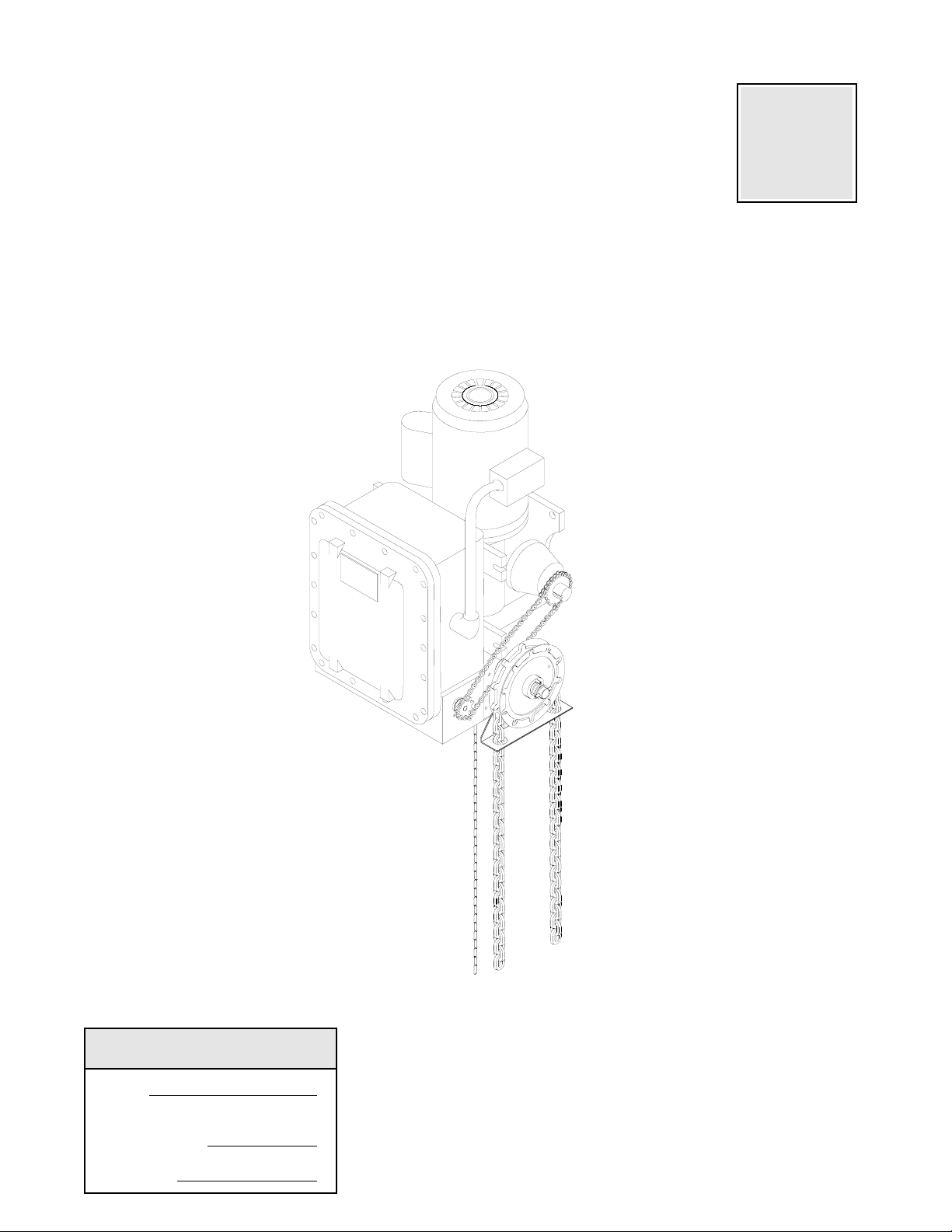
OWNER'S MANUAL
HAZARDOUS (NEMA 7/9)
INDUSTRIAL DUTY DOOR OPERATOR
Serial #
(located on electrical box cover)
Installation Date
Wiring Type
2 YEAR WARRANTY
NOT FOR RESIDENTIAL USE
FACTORY SET
C2 Wiring
See page 8 for
other wiring
configurations
Page 2
2
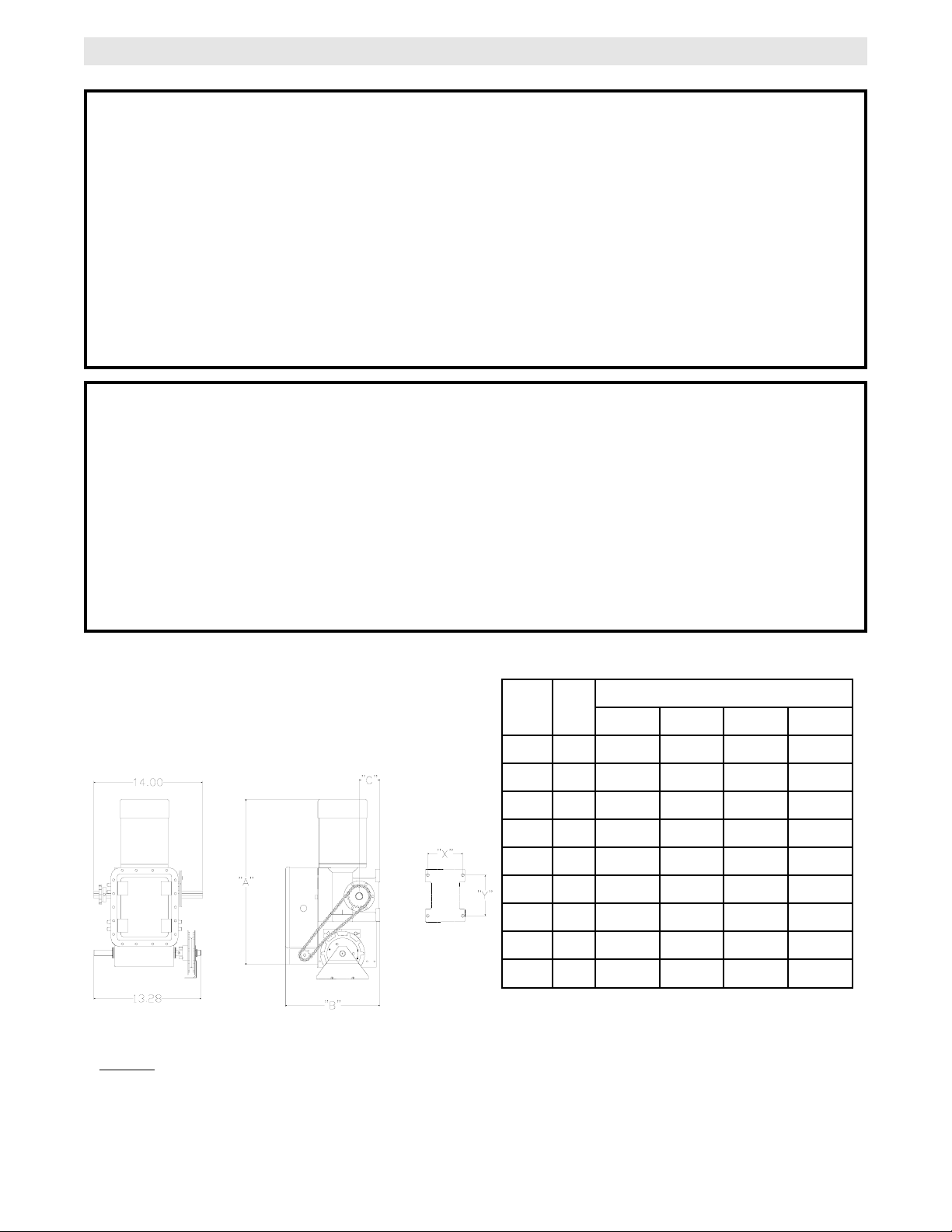
SPECIFICATIONS
WEIGHTS AND DIMENSIONS
HANGING WEIGHT:.........207 LBS.
A
11-1/2
12-1/2
12-3/4
12-3/4
11
11
12
12-1/2
12-3/4
B
25-3/4
26-3/4
27
27
25-1/4
25-1/4
26-1/4
26-3/4
27
C
12-63/64
12-63/64
12-63/64
13-63/64
12-63/64
12-63/64
12-63/64
13-63/64
13-63/64
D
3
3
3
3-1/2
3
3
3
3-1/2
3-1/2
1/2
3/4
1
1-1/2
1/2
3/4
1
1-1/2
2
1
1
1
1
3
3
3
3
3
HP
DIMENSIONS
NOTES:
1) Output Shaft with 1” x 1/4” Key.
2) MT’G CENTERS: X = 4-3/4”; Y = 5-1/2”
3) Hand Chain Wheel extends 1-5/8” beyond operator in vertical mounting position as shown.
MECHANICAL
DRIVE REDUCTION:.............45:1 Reduction
Heavy duty bronze worm
gear reducer
OUTPUT SHAFT SPEED:.....43 R.P.M.
DOOR SPEED:......................4 - 10" per sec.
depending on door
BRAKE: .................................Dynamic brake
HOIST WHEEL:.....................Standard mounting on
left or right side
SAFETY
DISCONNECT:.............Floor level chain hoist with elect-
rical interlock for emergency manual door operation
REVERSING EDGE:.....(Optional) Electric or pneumatic
sensing device attached to the bottom edge of door.
A REVERSING EDGE IS STRONGLY
RECOMMENDED FOR
ALL
COMMERCIAL
OPERATOR INSTALLATIONS.
REQUIRED
WHEN
THE 3 BUTTON CONTROL STATION IS OUT OF
SIGHT OF DOOR OR ANY OTHER CONTROL
(AUTOMATIC OR MANUAL) IS USED.
MOTOR
TYPE: .................................Continuous duty
HORSEPOWER:.................1/2, 3/4, 1 & 1-1/2 Hp
Single or Three phase
2 HP Three phase
SPEED:...............................1725 RPM
VOLTAGE: ..........................115, 220, 230 Single phase
230, 460, 575 Three phase
CURRENT: .........................See motor nameplate
ELECTRICAL
TRANSFORMER:.............24VAC
CONTROL STATION: ......NEMA 1 three button station.
OPEN/CLOSE/STOP
WIRING TYPE:.................C2 (Standard)
Momentary contact to OPEN/CLOSE/STOP plus wiring
for sensing device to reverse and auxiliary devices to
open and close with open override.
(Other types available. See chart, Pg. 8)
LIMIT ADJUST:................Linear driven, fully
adjustable screw type cams. Adjustable to 30 feet.
PHASE
Page 3
3
TO AVOID DAMAGE TO DOOR AND OPERATOR,
MAKE ALL DOOR LOCKS INOPERATIVE. SECURE
LOCK(S) IN "OPEN" POSITION.
IF THE DOOR LOCK NEEDS TO REMAIN
FUNCTIONAL, INSTALL AN INTERLOCK SWITCH.
DO NOT CONNECT ELECTRIC POWER UNTIL
INSTRUCTED TO DO SO.
KEEP DOOR BALANCED. STICKING OR BINDING
DOORS MUST BE REPAIRED. DOORS, DOOR
SPRINGS, CABLES, PULLEYS, BRACKETS AND
THEIR HARDWARE MAY BE UNDER EXTREME
TENSION AND CAN CAUSE SERIOUS PERSONAL
INJURY. CALL A PROFESSIONAL DOOR
SERVICEMAN TO MOVE OR ADJUST DOOR
SPRINGS OR HARDWARE.
WARNING
CAUTION
WARNING
WARNING
WARNING
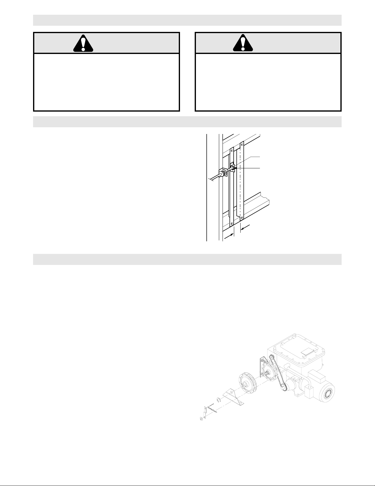
SITE PREPARATIONS
It is imperative that the wall or mounting surface
provide adequate support for the operator.
This surface must:
a) Be rigid to prevent play between operator and
door shaft.
b) Provide a level base.
c) Permit the operator to be fastened securely and
with the drive shaft parallel to the door shaft.
The safety and wear of the operator will be adversely
affected if any of the above requirements are not met.
For metal buildings, fasten 2” x 2” x 3/16” (or larger)
angle iron frames to the building purlins. Retain 51/2” between frames. See Figure 1.
OPERATOR PREPARATION
IMPORTANT SAFETY NOTES
5-1/2”
The N9GH operator may be mounted on either the right (standard) or left side of door, and in either a vertical
(standard) or horizontal mounting position. Refer to the steps below if you require the hand chain and/or
disconnect chain to be on the opposite side of the operator; Or if the operator is being mounted in a horizontal
position.
Hand Chain Right/Left Conversion
Remove the two snap rings (1 pc. outer, 1 pc inner)
on hand chain shaft assembly. Position roll-pin to fit
through cutout in frame and slide complete shaft
assembly through housing and bevel gear. Insert
shaft assembly on opposite side of housing, and
replace bevel gear, bearing, hardware, and snap rings
on the opposite side of shaft in the same manner.
Disconnect Lever Right/Left Conversion
Remove cotter pins on the ends of the disconnect
shaft (square shaft), move the disconnect lever arm to
the opposite side, and replace the cotter pins. Be
sure to keep two(2) 12ga. washers on the side without
the lever arm.
Horizontal Mounting Conversion
Remove cotter pins on the ends of the disconnect
shaft (square shaft), and remove lever. Replace lever
using square hole on opposite end of lever.
Reposition sash chain to opposite end of lever also.
Replace cotterpins.
FIGURE 2
CAUTION
WARNING
Shaft Support Bracket
with Bearing (Not Supplied)
Door Sprocket
2-1/4"
FIGURE 1
Page 4
4
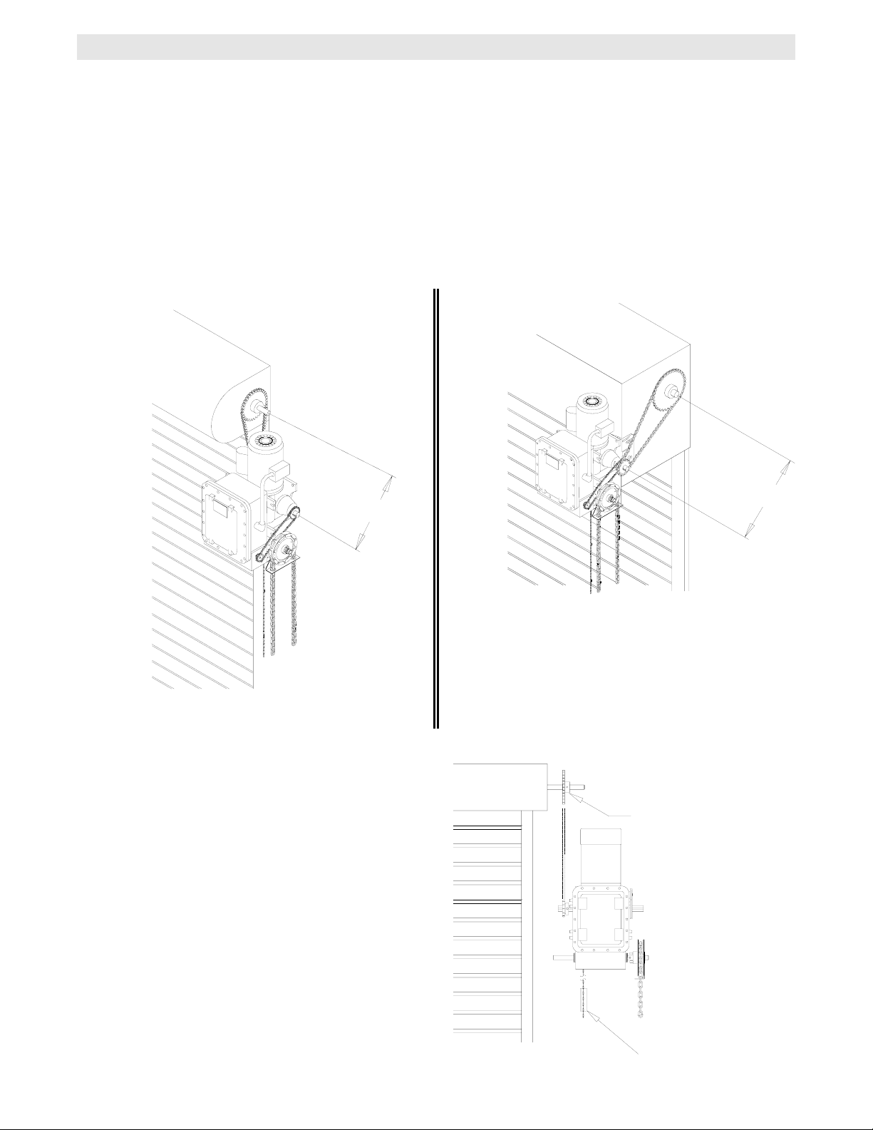
1a. Wall Mounting
The operator should generally be installed below
the door shaft, and as close to the door as
possible. The optimum distance between the door
shaft and operator drive shaft is between 12” - 15”.
Refer to Figure 3.
OPERATOR MOUNTING
IMPORTANT:
The shelf or bracket must
provide adequate support, prevent play
between operator and door shaft, and permit
operator to be fastened securely and with the
drive shaft parallel to the door shaft.
1b. Bracket or Shelf Mounting
The operator may be mounted either above or
below the door shaft. The optimum distance
between the door shaft and operator drive shaft
is between 12” - 15”. Refer to Figure 4.
1c. Place door sprocket on the door shaft. Do not
insert the key at this time.
2. Place drive sprocket on the appropriate side of
the operator. Do not insert the key at this time.
3. Wrap drive chain around door sprocket and join
roller chain ends together with master link.
4. Raise operator to approximate mounting position
and position chain over operator sprocket.
5. Raise or lower operator until the chain is taut (not
tight). Make sure the operator output shaft is
parallel to door shaft and sprockets are aligned.
When in position, secure the operator to wall or
mounting bracket.
6. Align sprockets and secure, (see Figure 5).
FIGURE 4
FIGURE 3
Before your operator is installed, be sure the door has been properly aligned and is working smoothly. The
operator may be wall mounted or mounted on a bracket or shelf. If necessary, refer to the operator preparations
on page 3. Refer to the illustration and instructions below that suits your application.
Be sure door
sprocket is properly
aligned with drive
before securing to
the shaft.
Chain Keeper
FIGURE 5
Optimum Distance
12 - 15”
Optimum Distance
12 - 15”
Page 5
These operators are equipped with a manual hoist. An
electrical interlock will disable the electrical controls
when the hoist is used.
To operate the hoist:
1. Pull the disconnect chain (small chain) to engage
the hoist mechanism. The disconnect chain may be
locked in position by slipping the end through the
keyhole of the chain keeper mounted on the wall.
2. Operate the door in the desired direction by pulling
on one side or the other of the continuous loop hoist
chain (large chain).
3. The disconnect chain must be released from the
chain keeper before the door will operate again
electrically.
5
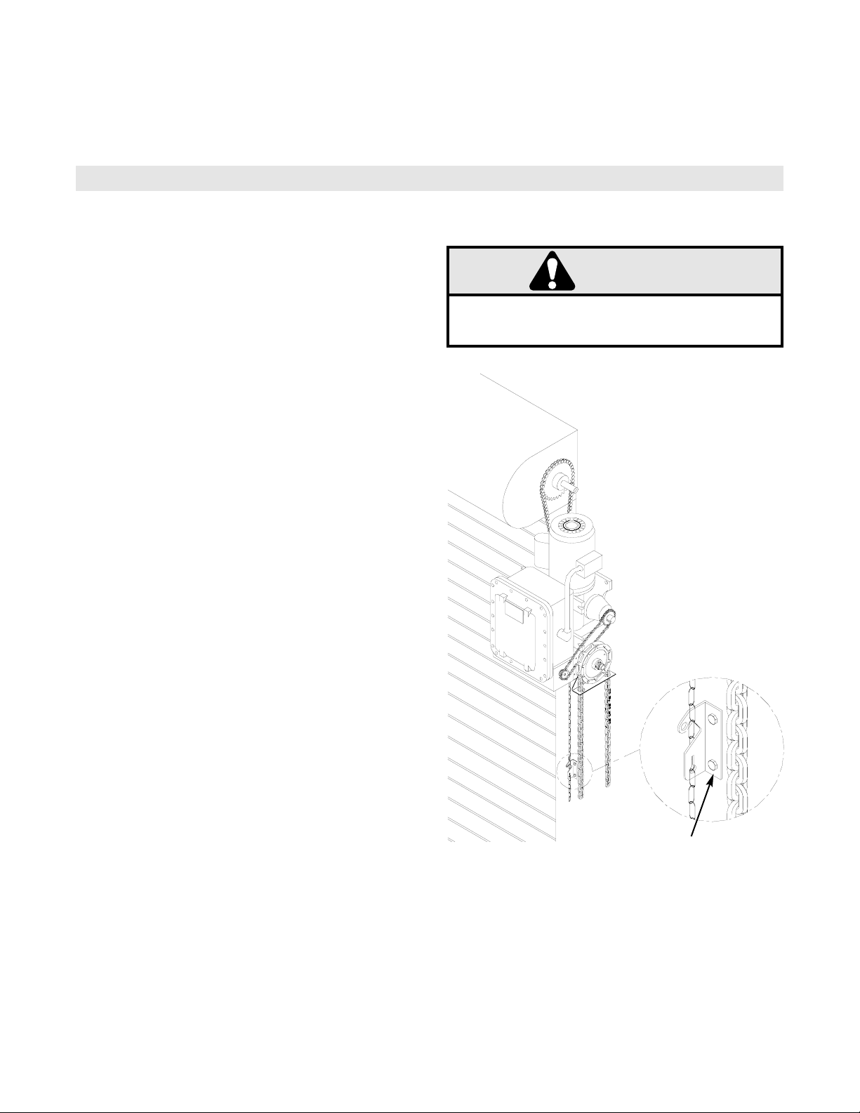
7. Install Hand Chain
Place hand chain around hand chain wheel. Be
sure to pass it through both openings in the chain
guide. Remove enough links so chain hangs
approximately two feet above the floor
EMERGENCY MANUAL OPERATION
This operator has provisions for manually operating the door in case of emergency or power failure. Refer to the
appropriate instructions below for your model operator.
Model N9GH
Chain Keeper
(with pad locking provisions)
8. Mount Chain Keeper / Keyhole Bracket
Using suitable hardware mount the chain keeper
approximately 4 feet above the floor, near the free
hanging chain. Remove disconnect sash chain
from bag and place the end through the keyhole
in the the chain keeper. Remove excess links if
necessary.
TURN OFF POWER TO THE OPERATOR BEFORE
MANUALLY OPERATING YOUR DOOR.
WARNING
CAUTION
WARNING
WARNING
Chain Keeper
CAUTION
Page 6
6
TO AVOID SERIOUS PERSONAL INJURY OR DEATH
FROM ELECTROCUTION, DISCONNECT ELECTRIC
POWER BEFORE MANUALLY MOVING LIMIT NUTS.
WARNING
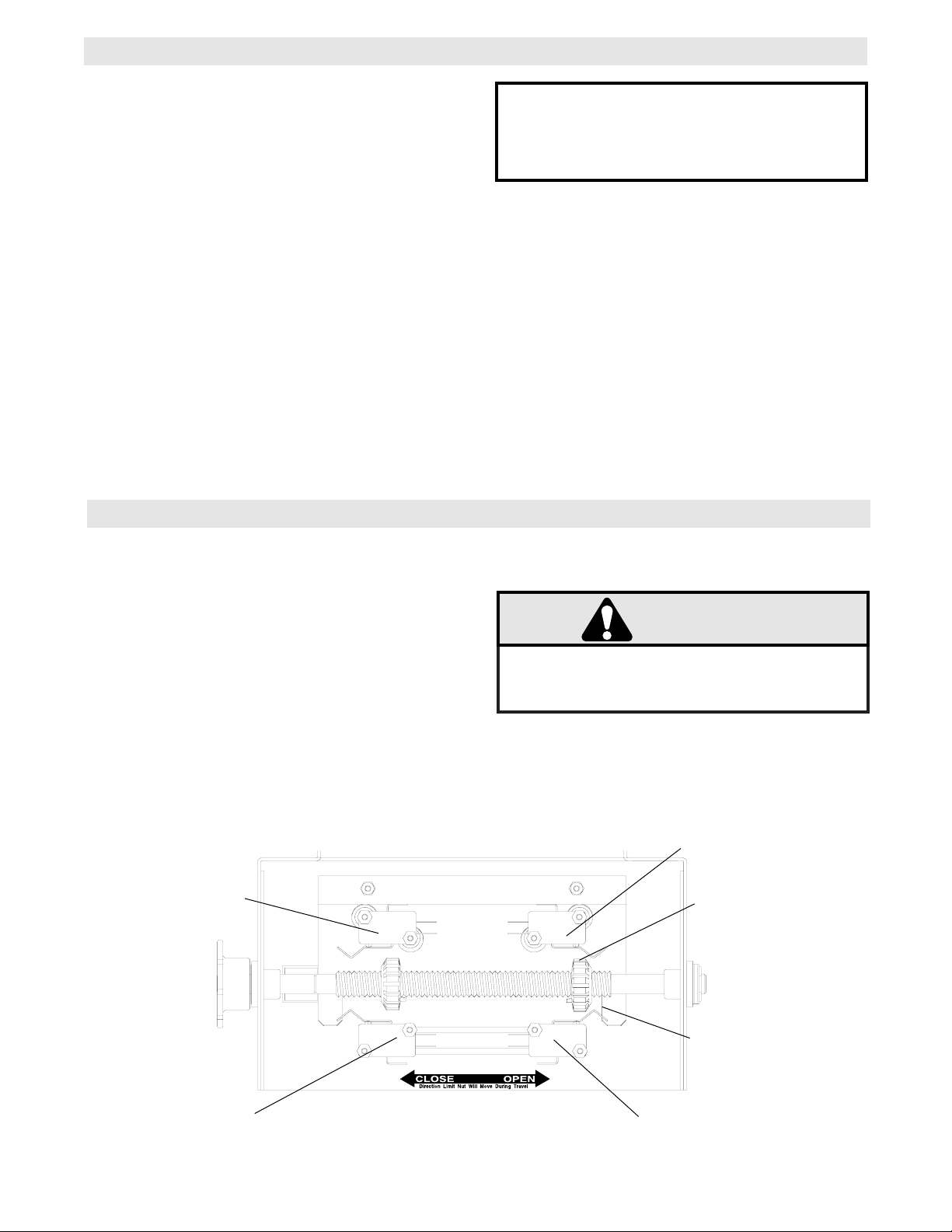
LIMIT SWITCH ADJUSTMENT
MAKE SURE THE LIMIT NUTS ARE POSITIONED BETWEEN THE LIMIT SWITCH ACTUATORS BEFORE
PROCEEDING WITH ADJUSTMENTS.
If other problems persist, call our toll-free number for
assistance - 1-800-528-2806.
1. To adjust limit nuts depress retaining plate to allow
nut to spin freely. After adjustment, release plate
and ensure it seats fully in slots of both nuts.
2. To increase door travel, spin nut away from
actuator. To decrease door travel, spin limit nut
toward actuator.
3. Adjust open limit nut so that door will stop in open
position with the bottom of the door even with top
of door opening.
4. Repeat Steps 1 and 2 for close cycle. Adjust close
limit nut so that actuator is engaged as door fully
seats at the floor.
Retaining Plate
CLOSE Limit Switch
SAFETY
(Aux. Close) Limit Switch
OPEN Limit Switch
Actuator
Aux. OPEN Limit Switch
SENSING EDGES
All types of sensing edges with an isolated normally
open (N.O.) output are compatible with your operator.
This includes pneumatic and electric edges. If your
door does not have a bottom sensing edge and you
wish to purchase one, contact the supplier of your
operator.
If not pre-installed by the door manufacturer, mount
the sensing edge on the door according to the
instructions provided with the edge. The sensing
edge may be electrically connected by either coiled
cord or take-up reel. Refer to the steps below.
Important Notes:
a) Proceed with Limit Switch Adjustments before
making any sensing edge wiring connections to
operator as described below.
b) Electrician must hardwire the junction box to the
operator electrical box in accordance with local
codes.
ENTRAPMENT PROTECTION ACCESSORIES (OPTIONAL)
IT IS STRONGLY RECOMMENDED THAT A
SENSING EDGE OR OTHER ENTRAPMENT
PROTECTION DEVICE BE USED IN
CONJUNCTION WITH THIS OPERATOR.
WIRING:
For wiring of your sensing device to the operator,
refer to the wiring diagram supplied with your
operator. See field connection terminals identified
as Sensing Device or Safety Edge.
TAKE-UP REEL: Take-up reel should be installed
12" above the top of the door.
COIL CORD: Connect operator end of coil cord to
junction box (not supplied) fastened to the wall
approximately halfway up the door opening.
WARNING
Page 7
7
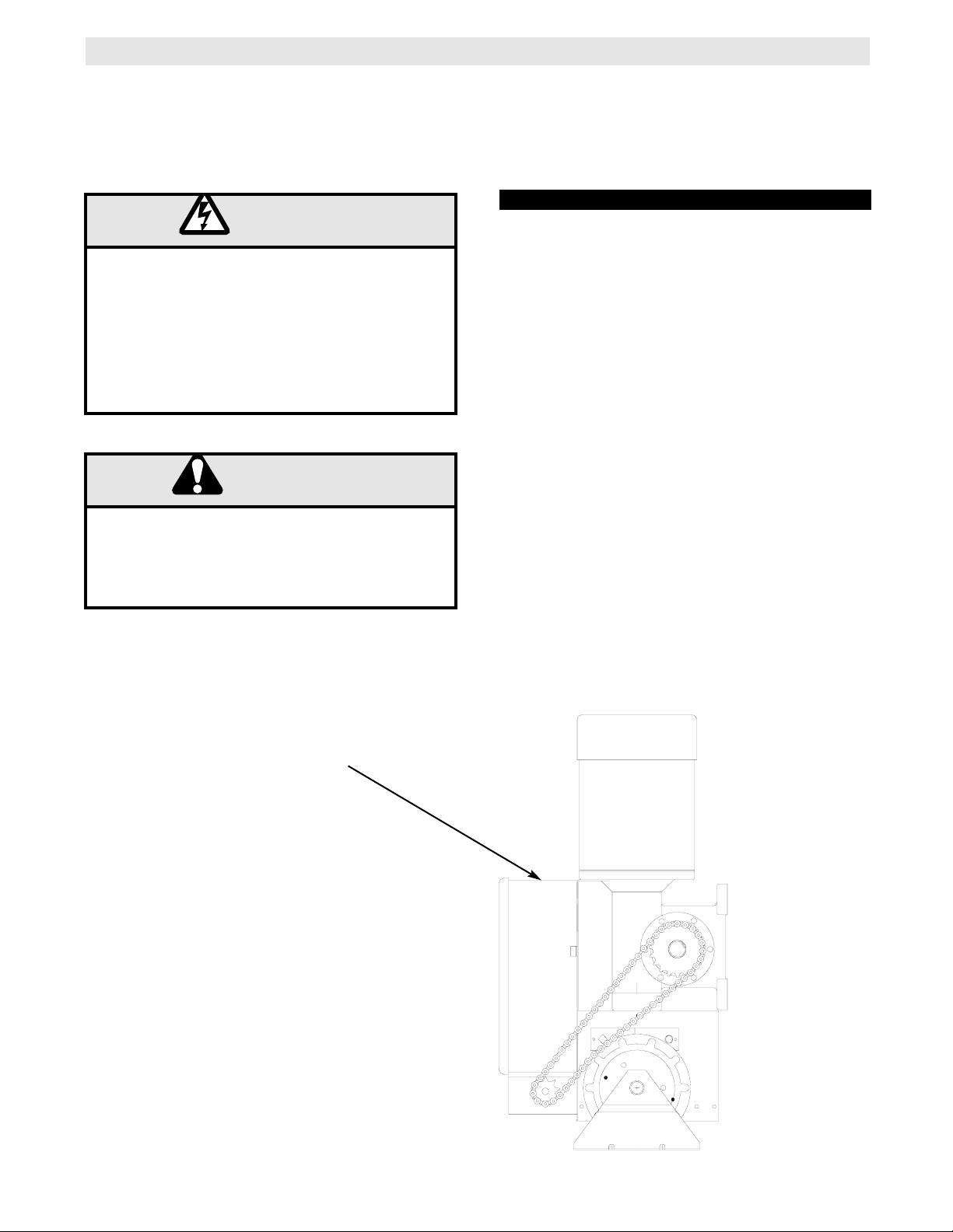
POWER WIRING CONNECTIONS
3/4-14 NPT FOR
POWER WIRING
CONDUIT ACCESS
POWER WIRING
1. Be sure that the power supply is of the correct
voltage, phase, frequency, and amperage to supply
the operator. Refer to the operator nameplate on the
cover.
2. Using the 3/4-14 NPT conduit access as shown
below, bring supply lines to the operator and connect
wires to the terminals indicated on the WIRING
CONNECTIONS DIAGRAM.
DO NOT TURN POWER ON UNTIL YOU HAVE
FINISHED MAKING ALL POWER AND CONTROL
WIRING CONNECTIONS AND HAVE COMPLETED
THE LIMIT SWITCH ADJUSTMENT PROCEDURE.
IMPORTANT: THIS UNIT MUST BE PROPERLY
GROUNDED. A GROUND SCREW IS SUPPLIED IN
THE ELECTRICAL BOX FOR CONNECTION OF
THE POWER SUPPLY GROUND WIRE. FAILURE
TO PROPERLY GROUND THIS UNIT COULD
RESULT IN ELECTRIC SHOCK AND SERIOUS
INJURY.
Remove the cover from the electrical enclosure. Inside this enclosure you will find the wiring diagram(s)
for your unit. Refer to the diagram (glued on the inside of the cover) for all connections described below.
If this diagram is missing, call the number on the back of this manual. DO NOT INSTALL ANY WIRING OR
ATTEMPT TO RUN THIS OPERATOR WITHOUT CONSULTING THE WIRING DIAGRAM.
DISCONNECT POWER AT THE FUSE BOX BEFORE
PROCEEDING.
OPERATOR MUST BE PROPERLY GROUNDED AND
PERMANENTLY WIRED IN ACCORDANCE WITH
LOCAL ELECTRICAL CODES. NOTE: THE
OPERATOR SHOULD BE ON A SEPARATE FUSED
LINE OF ADEQUATE CAPACITY.
ALL ELECTRICAL CONNECTIONS MUST BE MADE
BY A QUALIFIED INDIVIDUAL.
WARNING
TO AVOID DAMAGE TO DOOR AND OPERATOR,
MAKE ALL DOOR LOCKS INOPERATIVE. SECURE
LOCK(S) IN "OPEN" POSITION.
IF THE DOOR LOCK NEEDS TO REMAIN
FUNCTIONAL, INSTALL AN INTERLOCK SWITCH.
WARNING
WARNING
Page 8
8
CONTROL WIRING
LOCATING THE CONTROL STATION
All operators are supplied with some type of control station. Generally a three button station
(OPEN/CLOSE/STOP) is provided. A two-position key switch or control station (OPEN/CLOSE) may be added or
substituted when requested at the time of order. Mount the control station near the door.
WARNING
INSTALL THE CONTROL STATION WHERE THE
DOOR IS VISIBLE, BUT AWAY FROM THE DOOR AND
ITS HARDWARE. IF CONTROL STATION CANNOT BE
INSTALLED WHERE DOOR IS VISIBLE, OR IF ANY
DEVICE OTHER THAN THE CONTROL STATION IS
USED TO A CTIVATE THE DOOR,
A REVERSING EDGE
MUST
BE INSTALLED ON THE BOTTOM OF THE
DOOR.
FAILURE TO INSTALL A REVERSING EDGE
UNDER THESE CIRCUMSTANCES MAY RESULT IN
SERIOUS INJURY OR DEATH TO PERSONS
TRAPPED BENEATH THE DOOR.
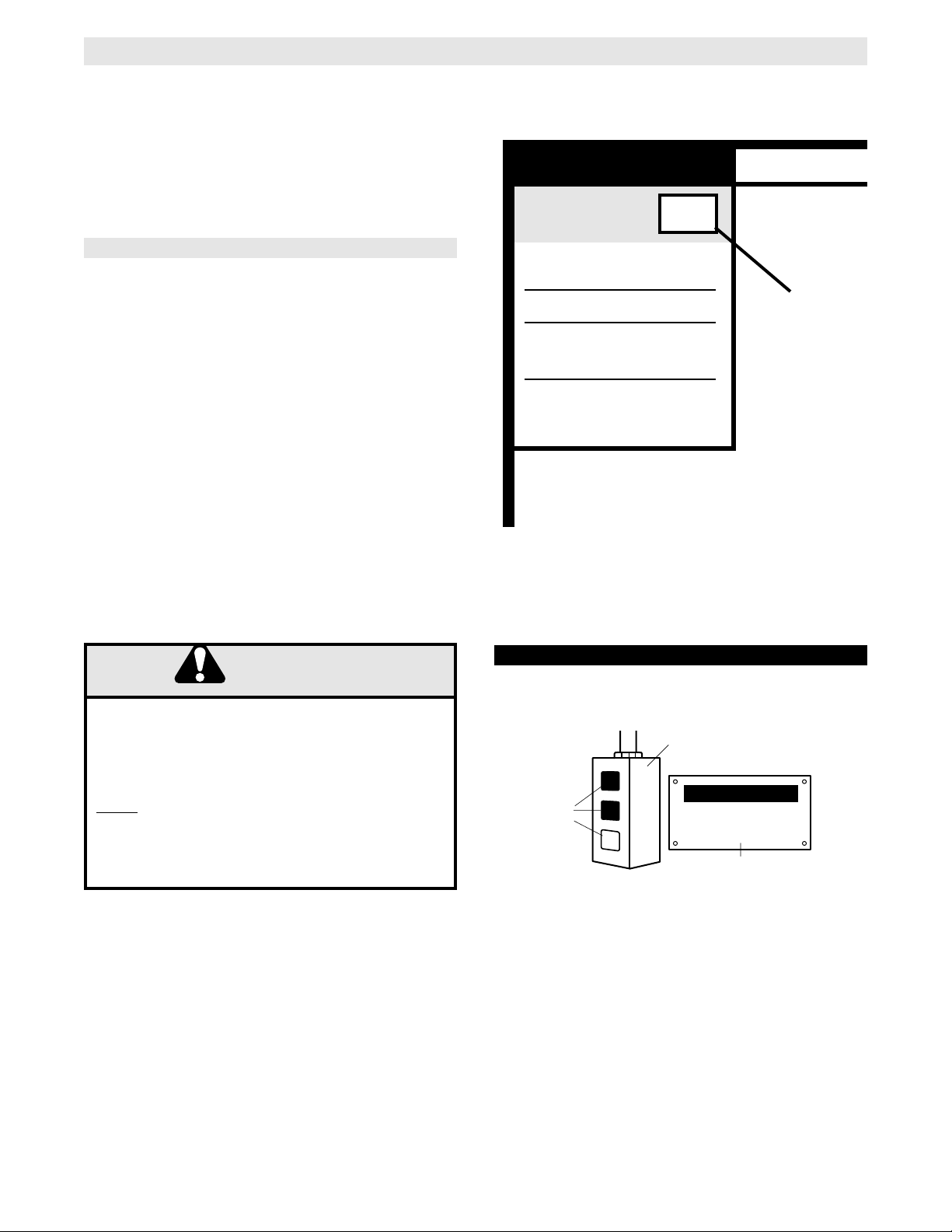
CLOSE
IMPORTANT: Mount WARNING NOTICE beside or
below the push button station.
MOUNT WARNING NOTICE
DETERMINE WIRING TYPE
Refer to the wiring diagram located on the inside cover the electrical box to determine the type of control wiring.
Wiring Diagram label on inside cover
of electrical box
Wiring
Type
SPECIAL CONTROL WIRING
If your operator was shipped from the factory with
non-standard control wiring or with optional
accessories that require addition instructions, refer to
the wiring diagram(s) indicated in the special control
wiring data box. When a replacement wiring diagram
is present, wiring diagrams in this manual will not
apply. Refer only to the replacement wiring diagram
for all connections.
IMPORTANT NOTE: If your wiring diagram is
missing, or you are unsure of the wiring type for
your operator, contact the customer service
department @ 1-800-528-2806.
Standard C2 Wiring
Standard operators are shipped from the factory with
jumper set for C2 wiring, which requires constant
pressure on button to close the door.
Additional Access Control Equipment
Locate any additional access control equipment as desired (but so that the door will be in clear sight of the person
operating the equipment), and connect to the terminal block in the electrical enclosure as shown on the FIELD
WIRING CONNECTIONS diagram. Any control with a normally (N.O.) isolated output contact may be connected
in parallel with the OPEN button. More than one device may be connected in this manner. Use 16 gauge wire or
larger for all controls. DO NOT USE THE CONTROL CIRCUIT TRANSFORMER (24VAC) IN THE OPERATOR
TO POWER ANY ACCESS CONTROL EQUIPMENT.
External Interlock Switch
The operator has a terminal connection for an external interlock switch. This switch must be a normally closed
(N.C.) two-wire device with a contact rating of at least 3 amps @ 24VAC. When such a switch is connected as
shown on the FIELD WIRING CONNECTIONS diagram, the control circuit will be disabled when the switch is
actuated, thereby preventing electrical operation of the door from the control devices.
SPECIAL CONTROL
WIRING DATA
This Operator has
WIRI
Control Wiring.
SUPPLEMENTAL WIRING DIAGRAM(S)
REPLACEMENT WIRING DIAGRAM
Note: Supplemental Wiring Diagrams are
to be used in addition to 1742-1.
Replacement Wiring Diagram is to be used
in place of 1742-1.
WARNING
Control Station
OPEN
Push
Buttons
C
STOP
LO
SE
WARNING
TO PREVENT ENTRAPMENT
DO NOT START DOOR DOWNWARD
UNLESS DOORWAY IS CLEAR
WARNING Notice
Page 9

9
TEST THE SYSTEM
Turn on power. Test all controls and safety devices to
make sure they are working properly. It will be
necessary to refer back to page 6 for fine adjustment
of the limit switches.
IMPORTANT NOTES:
Do not leave operator power on unless all safety
and entrapment protection devices have been
tested and are working properly.
Be sure you have read and understand all Safety
Instructions included in this manual.
Be sure the owner or person(s) responsible for
operation of the door have read and understand
the Safety Instructions, know how to electrically
operate the door in a safe manner, and know how
to use the manual disconnect operation of the
door operating system.
WARNING
DO NOT PLACE HANDS OR TOOLS IN OR NEAR
THE OPERATOR WHEN THE POWER IS ON OR
WHEN TESTING CONTROL OR SAFETY
DEVICES. ALWAYS DISCONNECT POWER
BEFORE SERVICING OR ADJUSTING THE
OPERATOR.
The operator has been pre-wired to accept
connection of a reversing edge device. Connect the
normally open contacts to terminals T10 and T11 on
the low voltage terminal block. A cut-off switch will deactivate the safety device during the last few inches of
the door's downward travel.
IF CONTROL STATION CANNOT BE INSTALLED WHERE
DOOR IS VISIBLE, OR IF ANY DEVICE OTHER THAN
THE CONTROL STATION IS USED TO ACTIVATE THE
DOOR,
A REVERSING EDGE MUST BE INSTALLED ON
THE BOTTOM OF THE DOOR.
FAILURE TO INSTALL A
REVERSING EDGE UNDER THESE CIRCUMSTANCES
MAY RESULT IN SERIOUS PERSONAL INJURY OR
DEA TH T O PERSONS TRAPPED BENEATH THE DOOR.
CONNECT REVERSING EDGE DEVICE (OPTIONAL)
NOTICE:
This equipment has been tested and found to comply with the limits for a Class A digital
device, pursuant to Part 15 of the FCC Rules. These limits are designed to provide
reasonable protection against harmful interference when the equipment is operated in a
commercial environment. This equipment generates, uses, and can radiate radio
frequency energy and, if not installed and used in accordance with the instruction
manual, may cause harmful interference to radio communications. Operation of this
equipment in a residential area is likely to cause harmful interference, in which case the
user will be required to correct the interference at his own expense.
WARNING
WARNING
WARNING
Page 10

10
HOW TO ORDER REPAIR PARTS
OUR LARGE SERVICE ORGANIZATION
SPANS AMERICA
INSTALLATION AND SERVICE INFORMATION
ARE AVAILABLE 6 DAYS A WEEK
CALL OUR TOLL FREE NUMBER - 1-800-528-2806
HOURS 7:00 TO 3:30 p.m. (Mountain Std. Time)
MONDAY Through SATURDAY
WHEN ORDERING REPAIR PARTS
PLEASE SUPPLY THE FOLLOWING INFORMATION:
PART NUMBER DESCRIPTION MODEL NUMBER
ADDRESS ORDER TO:
THE CHAMBERLAIN GROUP, INC.
Electronic Parts & Service Dept.
2301 N. Forbes Blvd., Suite 104
Tucson, AZ 85745
MAINTENANCE SCHEDULE
Use SAE 30 Oil (Never use grease or silicone spray).
T Repeat ALL procedures.
Do not lubricate motor. Motor bearings are rated for continuous operation.
Inspect and service whenever a malfunction is observed or suspected.
CA UTION: BEFORE SERVICING, AL WAYS DISCONNECT OPERA T OR FR OM POWER SUPPLY.
Check at the intervals listed in the following chart.
EVERY EVERY EVERY
ITEM PROCEDURE 3 MONTHS 6 MONTHS 12 MONTHS
Drive Chain Check for excessive slack.
Check & adjust as required.
Lubricate.*
z T
Sprockets Check set screw tightness z T
Fasteners Check & tighten as required z T
Manual Disconnect Check & Operate z T
Bearings & Shafts Check for wear & lubricate z T
Page 11

11
AVAILABLE ACCESSORIES
Available Accessories for N9GH Operators
Part Number
PUSH BUTTON CONTROL STATION
Style
Description
02 101
Indoor Surface Mount (NEMA 1) Single Button, Steel Enclosure
02 102
Indoor Surface Mount (NEMA 1) Two Button, Steel Enclosure
02 103
Indoor Surface Mount (NEMA 1) Three Button, Steel Enclosure
02 103 L
Indoor Surface Mount (NEMA 1) Three Button, With Maintenance Alert System
02 106
Indoor Flush Mount (NEMA 1) Single Button, Stainless Faceplate
02 107
Indoor Flush Mount (NEMA 1) Two Button, Stainless Faceplate
02 108
Indoor Flush Mount (NEMA 1) Three Button, Stainless Faceplate
02 401
Outdoor Surface Mount (NEMA 4/12) Single Button, Die Cast Enclosure
02 402
Outdoor Surface Mount (NEMA 4/12) Two Button, Die Cast Enclosure
02 403
Outdoor Surface Mount (NEMA 4/12) Three Button, Die Cast Enclosure
02 403 P
Outdoor Surface Mount (NEMA 4/12) Three Button, Polycarbonate Enclosure
02 406
Outdoor Surface Mount (NEMA 4/12) Three Button With Key, Die Cast Enclosure
02 703
Hazdardous Area (NEMA 7/9) Three Button, Die Cast Enclosure
PULL-SWITCH CONTROLS
02 111
Indoor Overhead Mount (NEMA 1) Single Pull-Switch, Steel Enclosure
02 411
Outdoor Overhead Mount (NEMA 4/12) Single Pull-Switch, Steel Enclosure
02 711
Hazdardous Area Overhead Mount (NEMA 7/9) Single Pull-Switch, Die Cast Enclosure
KEY CONTROL STATIONS
02 109
Indoor Flush Mount (NEMA 1), Tamperproof Two Position, Steel/Aluminum Enclosure
02 109 B
Indoor Flush Mount (NEMA 1), Tamperproof Two Position, Steel/Aluminum Enclosure
02 109 U
Indoor Flush Mount (NEMA 1), Tamperproof Two Position, Steel/Aluminum Enclosure
02 109 C
Indoor Flush Mount (NEMA 1), Tamperproof Two Position, Steel/Aluminum Enclosure
02 110
Indoor Flush Mount (NEMA 1), Tamperproof Two Position With Stop Button, Steel/Aluminum Enclosure
02 110 B
Indoor Flush Mount (NEMA 1), Tamperproof Two Position With Stop Button, Steel/Aluminum Enclosure
02 110 U
Indoor Flush Mount (NEMA 1), Tamperproof Two Position With Stop Button, Steel/Aluminum Enclosure
02 110 C
Indoor Flush Mount (NEMA 1), Tamperproof Two Position With Stop Button, Steel/Aluminum Enclosure
02 409
Outdoor Surface Mount (NEMA 4/12), Tamperproof Two Position, Die Cast Enclosure
02 409 B
Outdoor Surface Mount (NEMA 4/12), Tamperproof Two Position, Die Cast Enclosure
02 409 U
Outdoor Surface Mount (NEMA 4/12), Tamperproof Two Position, Die Cast Enclosure
02 409 C
Outdoor Surface Mount (NEMA 4/12), Tamperproof Two Position, Die Cast Enclosure
02 410
Outdoor Surface Mount (NEMA 4/12), Tamperproof Two Position, With Stop Button, Die Cast Enclosure
02 410 B
Outdoor Surface Mount (NEMA 4/12), Tamperproof Two Position, With Stop Button, Die Cast Enclosure
02 410 U
Outdoor Surface Mount (NEMA 4/12), Tamperproof Two Position, With Stop Button, Die Cast Enclosure
02 410 C
Outdoor Surface Mount (NEMA 4/12), Tamperproof Two Position, With Stop Button, Die Cast Enclosure
02 404
Outdoor Surface Mount (NEMA 4/12), Non-Tamperproof
Two Position, Die Cast Enclosure
180C0152
Outdoor Surface Mount (NEMA 4/12), Non-Tamperproof Two Position, Die Cast Enclosure
02 405
Outdoor Surface Mount (NEMA 4/12), Non-Tamperproof Two Position, With Stop Button, Die Cast Enclosure
02 407
Outdoor Surface Mount (NEMA 4/12), Non-Tamperproof Two Position, Die Cast Enclosure
SENSING EDGES
65 8202
Pneumatic Sensing Edge 2 Wire
65 8302
Pneumatic Sensing Edge 2 Wire
65 5202
Pneumatic Sensing Edge
2 Wire
65 5302
Pneumatic Sensing Edge 2 Wire
65 8203
Electric Sensing Edge 2 Wire, Sectional, Sliding, Bi-fold Doors
65 8204
Electric Sensing Edge 2 Wire, Rolling Doors
VEHICLE DETECTION SYSTEM
65 8206
Pneumatic Sensing Treadle
2 Wire
Page 12

120V 1 PHASE SCHEMATIC/ FIELD WIRING DIAGRAM
12
Page 13

13
240V 1 PHASE SCHEMATIC/ FIELD WIRING DIAGRAM
Page 14

14
208/230V 3 PHASE SCHEMATIC/ FIELD WIRING DIAGRAM
Page 15

TEST THE SYSTEM
Turn on power. Test all controls and safety devices to
make sure they are working properly. It will be
necessary to refer back to page 6 for fine adjustment
of the limit switches.
IMPORTANT NOTES:
Do not leave operator power on unless all safety
and entrapment protection devices have been
tested and are working properly.
Be sure you have read and understand all Safety
Instructions included in this manual.
Be sure the owner or person(s) responsible for
operation of the door have read and understand
the Safety Instructions, know how to electrically
operate the door in a safe manner, and know how
to use the manual disconnect operation of the
door operating system.
WARNING
DO NOT PLACE HANDS OR TOOLS IN OR NEAR
THE OPERATOR WHEN THE POWER IS ON OR
WHEN TESTING CONTROL OR SAFETY
DEVICES. ALWAYS DISCONNECT POWER
BEFORE SERVICING OR ADJUSTING THE
OPERATOR.
The operator has been pre-wired to accept
connection of a reversing edge device. Connect the
normally open contacts to terminals T10 and T11 on
the low voltage terminal block. A cut-off switch will de-
activate the safety device during the last few inches of
the door's downward travel.
IF CONTROL STATION CANNOT BE INSTALLED WHERE
DOOR IS VISIBLE, OR IF ANY DEVICE OTHER THAN
THE CONTROL STATION IS USED TO ACTIVATE THE
DOOR,
A REVERSING EDGE MUST BE INSTALLED ON
THE BOTTOM OF THE DOOR.
FAILURE TO INSTALL A
REVERSING EDGE UNDER THESE CIRCUMSTANCES
MAY RESULT IN SERIOUS PERSONAL INJURY OR
DEA TH T O PERSONS TRAPPED BENEATH THE DOOR.
NOTICE:
This equipment has been tested and found to comply with the limits for a Class A digital
device, pursuant to Part 15 of the FCC Rules. These limits are designed to provide
reasonable protection against harmful interference when the equipment is operated in a
commercial environment. This equipment generates, uses, and can radiate radio
frequency energy and, if not installed and used in accordance with the instruction
manual, may cause harmful interference to radio communications. Operation of this
equipment in a residential area is likely to cause harmful interference, in which case the
user will be required to correct the interference at his own expense.
WARNING
460V 3 PHASE SCHEMATIC/ FIELD WIRING DIAGRAM
15
WARNING
WARNING
Page 16

16
REPAIR PARTS KITS – LIMIT BOX FOR MODEL N9GH
K72-14130 LIMIT SHAFT ASSEMBLY KIT
Item
L1
L2
L3
L4
L5
L6
L7
L8
Description
Limit Shaft
Flange Bearing, 3/8” I.D.
Limit Nut
Sprocket 48B9 x 3/8” Bore
Washer, Shim 3/8” I.D. x .050 THK.
Washer, Shim 3/8” I.D. x .010 THK.
Roll Pin, 1/8 DIA. x 1” Long
E Ring, 3/8”
Qty
1
2
2
1
1
4
1
1
P/N
11-13361
12-10028
13-10024
15-48B9A1
80-10025
80-10026
86-RP04-100
87-E-038
* COMPLETE LIMIT BOX KITS
Item
1
2
3
Description
Limit Box
Limit Box Cover
Terminal Block, 6 Position
Qty
1
1
2
P/N
10-17531
10-17532
42-106
Below are replacement kits available for your operator. For replacement of electrical box, motor or brake components be sure to match
model number of your unit to kit number below to ensure proper voltage requirements. Optional modifications and/or accessories
included with your operator may add or remove certain components from these lists. Please consult a parts and service representative
regarding availability of individual components of kits specified below. Refer to page 10 for all repair part ordering information.
Complete Electrical Box Replacement Kits
To order a complete electrical box replacement kit, add a Kprefix to the model number of your operator. For example:
N9GH5011M (Operator) = K-N9GH5011M (Elec. Box Kit)
Limit Box Sub-Assembly Kits
K72-14130 Limit Shaft Assembly
K75-12511 Limit Switch Assembly
Complete Gear Reducer Housing Kits
See Page 18 for more information
Shaft Assembly Kits
K72-12789 Hand Chain Shaft Assembly
K72-13379 Hand Chain Shaft Assembly
K75-12783 Disconnect Assembly
Individual Components
21-5115 Transformer, 115V Operators
21-5230 Transformer, 230V Operators
21-5460 Transformer, 380-460V Operators
Motor Kits for Model N9GH
(Gear Reduced Style Operators)
Item
S1
S2
S3
S4
S5
S6
S7
S8
S9
P/N
10-10013
10-12553
10-12806
18-10036
23-10041
31-12542
82-PX04-20
82-PX06-16
84-LH-06
Description
Depress Plate
Nut Plate, Switch
Backup Plate
Spring, Depress Plate
Limit Switch
Standoff, Limit Switch
Screw, #4-40 Pan Head Phillips
Screw, #6-32 x 1” Pan Hd Phillips
Locknut, #6-32 Nylon Hex
K75-12511 LIMIT SWITCH ASSEMBLY KIT
1 HORSE POWER
CIRCUIT TYPE
MODEL
1011 M 115 1 60 K20-1100C2X
1021 M 230 1 60 K20-1100C2X
1023 M 208/230 3 60 K20-3100C4X
1043 M 460 3 60 K20-3100C4X
VOLTS PHASE HZ
MOTOR KIT REQ
3/4 HORSE POWER
CIRCUIT TYPE
MODEL
7511 M 115 1 60 K20-1075C2X
7521 M 230 1 60 K20-1075C2X
7523 M 208/230 3 60 K20-3075C4X
7543 M 460 3 60 K20-3075C4X
VOLTS
PHASE HZ MOTOR KIT REQ
1/2 HORSE POWER
CIRCUIT TYPE
MODEL
5011 M 115 1 60 K20-1050C2X
5021 M 230 1 60 K20-1050C2X
5023 M 208/230 3 60 K20-3050C4X
5043 M 460 3 60 K20-3050C4X
VOLTS PHASE HZ MOTOR KIT REQ
1-1/2 HORSE POWER
CIRCUIT TYPE
MODEL
1511 M 115 1 60 K20-1150C2X
1521 M 230 1 60 K20-1150C2X
1523 M 208/230 3 60 K20-3150C4X
1543 M 460 3 60 K20-3150C4X
VOLTS PHASE
HZ
MOTOR KIT REQ
2 HORSE POWER
CIRCUIT TYPE
MODEL
2023 M 208/230 3 60 K20-3200C4X
2043 M 460 3 60 K20-3200C4X
VOLTS
PHASE
HZ MOTOR KIT REQ
*Limit Box Kits include parts from K72-14130 and K72-12511
Qty
1
4
4
2
4
4
8
2
2
Page 17

17
ILLUSTRATED PARTS – ELECTRICAL BOX
Page 18

18
REPAIR PARTS KITS – MODEL N9GH
Refer to the parts lists below for replacement kits available for your operator. If optional modifications and/or
accessories are included with your operator, certain components may be added or remove from these lists.
Individual components of each kit may not be available. Please consult a parts and service representative
regarding availability of individual components. Refer to page 10 for all repair part ordering information.
K75-12783 DISCONNECT ASSEMBLY KIT
ITEM PART # DESCRIPTION QTY
D1
D2
D3
D4
D5
D6
D7
D8
D9
D10
D11
D12
D13
D14
D15
D16
D17
D18
D19
D20
GH Disconnect Lever
Bevel Gear Yoke
Brake Release
Actuator Bracket
Switch Actuator
Disconnect Shaft
GH Tension Spring
12ft. Of Sash Chain
Screw, #8-32 x 1/4” Self Tap
Screw, #10-32 x 7/8” Long
Screw, #10-32 x 1/2” Serrated Fl.
Nut, #10-32 Serrated Flange
USS Flatwasher, 3/4”
#10 Lockwasher ZP
Cotter Pin, 1/8” x 1-3/4” Long
Roll Pin, 3/16” x 3” Black Oxide
Interlock Switch
Spacer
Screw, #6-32 x 1-3/8” Long
#6-32 Lock Nut
1
1
1
1
1
1
1
1
1
2
2
2
3
2
3
1
1
2
2
2
10-11021
10-11023
10-11024
10-17591
10-17590
11-11106
18-11007
19-17160
82-PX08-04T
82-SH10-14
82-WX10-08T
84-FN-10
85-FW-50
85-LS-10
86-CP04-112
86-RP06-300
23-10916
31-11119
82-PX06-19
84-LH-06
K72-12789 OR K72-13379
HAND CHAIN SHAFT KIT
ITEM PART # DESCRIPTION QTY
H1
H2
H3
H4
H5
H6
H7
H8
H9
H10
H11
H12
H13
H14
H15
Bevel Gear, 5/8” ID
Bevel Gear, 3/4” ID
Hand Chain Guide
Hand Chain Shaft, GH
Bearing, 3/4” I.D.
Nyliner Bearing
Compression Spring, GH
Chain Wheel Assembly
Shim Washer, Thick
Washer, .656 I.D. x 1.25 O.D.
Roll Pin, 1/4” x 1-1/2” Long
Roll Pin, 5/16” x 1-5/8” Long
Roll Pin, 5/16” x 2-1/2” Long
E Ring, 5/8”
E Ring, 3/4”
1
1
1
1
2
1
1
1
4
1
1
1
1
1
4
08-11012
08-11013
10-10882
11-11105
12-10029
12-10883
18-11008
75-10884
80-10022
80-11014
86-RP08-108
86-RP10-110
86-RP10-208
87-E-062
87-E-075
INDIVIDUAL PARTS
ITEM PART # DESCRIPTION QTY
1
2
3
4
5
6
7
Elec. Box Mounting Bracket
Sprocket, 48B18 LGE
Sprocket, 50B12 LGH
Electrical Box
Motor
Gear Reducer
Limit Box
1
1
1
1
1
1
1
10-11045
15-48B18LGE
15-50B12LGH
See Page 16
See Page 16
See Var. Comp.
See Page 16
COMPLETE GEAR REDUCER HOUSING KITS
ITEM PART # DESCRIPTION QTY
G1
G2
G3
G4
Housing Support Bracket
Gear Brake Housing
Housing Cover
Bottom Cover
2
1
1
1
10-11006
10-11026M1
10-11046M1
10-11031
* Gear Housing Kits also include:
K75-12788 Disconnect Assembly Kit
K72-12789 Hand Chain Shaft Kit
For All Operators
K75-17991
KIT REQUIRED FOR OPERATOR(S)
VARIABLE COMPONENTS
ITEM PART # DESCRIPTION QTY
6
Gear Reducer (1 HP Opers, 45:1)
Gear Reducer (1.5-2 HP Opers, 45:1)11
32-11009
32-11010
Page 19

ILLUSTRATED PARTS – MODEL N9GH
19
Page 20

REPAIR PARTS KITS – MODEL N9GH
Refer to the parts lists below for replacement kits available for your operator. If optional modifications and/or
accessories are included with your operator, certain components may be added or remove from these lists.
Individual components of each kit may not be available. Please consult a parts and service representative
regarding availability of individual components. Refer to page 10 for all repair part ordering information.
INDIVIDUAL PARTS
ITEM PART # DESCRIPTION QTY
1
2
3
4
5
6
7
8
9
10
11
12
13
14
15
16
17
18
Din Rail
Contactor
Mounting Plate
Transformer (Not Used on 115VAC)
Relay, 24V
Auxiliary Contact Block
Flex Conduit
Elbow
Ground Lug
Timer
Spacer
Terminal Block, 3 Pole
Enclosure
3 Phase, Dynamic Brake
1 Phase, Dynamic Brake
Intrinsically Safe Assembly
Bulk Head Assembly
Overload (3 PH Only)
Transformer
1
1
1
1
1
2
1
1
1
1
4
1
1
1
1
1
1
1
1
03-AB-DIN4
03-8024-D
10-17530
21-17524
24-24-1
27-8002-D
28-17535
28-17536
28-17579
29-438
31-17539
42-103
44-17529
74-17554
74-17555
74-17561
74-17585
See Overloads
See Page 16
20
OVERLOADS
OPERATOR
N9GH1023M
N9GH1043M
N9GH1053M
N9GH1523M
N9GH1543M
N9GH2023M
N9GH2043M
N9GH5023M
N9GH5043M
N9GH7523M
N9GH7543M
ITEM 17
25-4002-5D
1.5-2.0 Amp
25-4004-D
2.5-4.0 Amp
25-4006-D
4.0-6.0 Amp
25-4008-D
5.5-8.0 Amp
25-4001-5D
1.0-1.6 Amp
Page 21

ILLUSTRATED PARTS – MODEL N9GH
21
6
2
9
7
8
16
10
4
15
3
17
11
9
14
5
12
13
18
19
Page 22

OPERATOR NOTES
22
Page 23

OPERATOR NOTES
23
Page 24

CONTROL CONNECTION DIAGRAM
IMPORTANT NOTES:
1) The 3-Button Control Station provided must be connected for operation.
2) If a STOP button is not used, a jumper must be placed between termianls 3 and 4.
3) Auxiliary control equipment may be any normally open two wire device such as
pullswitch, single button, loop detector, card key or such device.
3 BUTTON STATION or 3 POSITION KEYSWITCH w/ SPRING RETURN TO CENTER AND STOP BUTTON
STANDARD
1 2 3 4
1 2 3 4
Open
Close
Stop
ALL CONTROL WIRING TYPES
2 BUTTON STATION or 3 POSITION KEYSWITCH w/ SPRING RETURN TO CENTER
STANDARD
1 2 4
1 2 4
2 OR MORE KEY LOCKOUT
Open
Close
Stop
2 OR MORE
Open
Close
Stop
SEE NOTE #2SEE NOTE #2 SEE NOTES
ATTENTION ELECTRICIAN:
USE 16 GAUGE OR HEAVIER WIRE
FOR ALL CONTROL CIRCUIT WIRING.
1 2 3 4
Open
Close
Stop
Keyswitch
ALL CONTROL WIRING TYPESALL CONTROL WIRING TYPES
1 BUTTON STATION or
ANY AUXILIARY DEVICE
3
7
#2 AND #3
Open
Close
ALL CONTROL WIRING TYPES
SENSING DEVICE TO REVERSE OR STOP
3
10
Sensing Device
ALL CONTROL WIRING TYPES
Open
Close
ALL CONTROL WIRING TYPES
Open
Close
4
ONE 2 OR MORE
OPEN / CLOSE
B2 or T1
WIRING TYPES ONLY
EXTERNAL INTERLOCK
Remove Jumper
When Interlock is Used
5
ALL CONTROL WIRING TYPES
4
5
01-17505B
©
2003, The Chamberlain Group, Inc.
All rights Reserved
 Loading...