

Page 1
Lift-Master
The Professional Line
OWNERS MANUAL
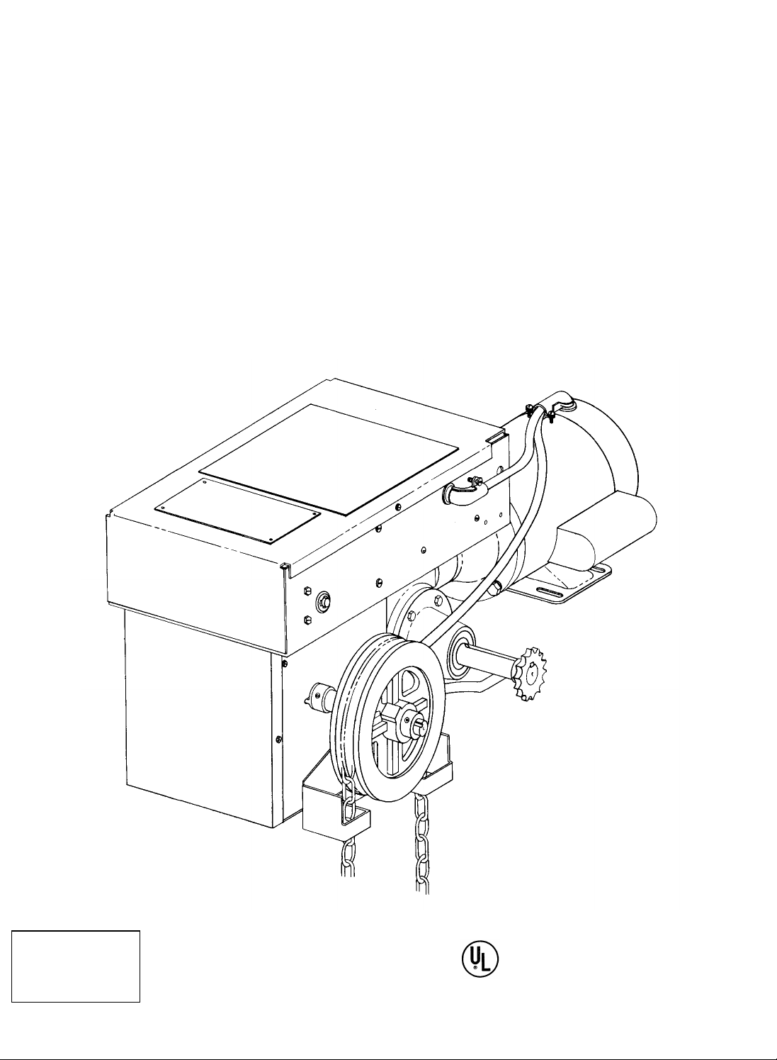
GEARHEAD JACKSHAFT
The Chamberlain Group, Inc.
A Unit of Duchossois Industries, Inc.
845 Larch Avenue, Elmhurst, Illinois 60126
MODEL GJ
SERIES B
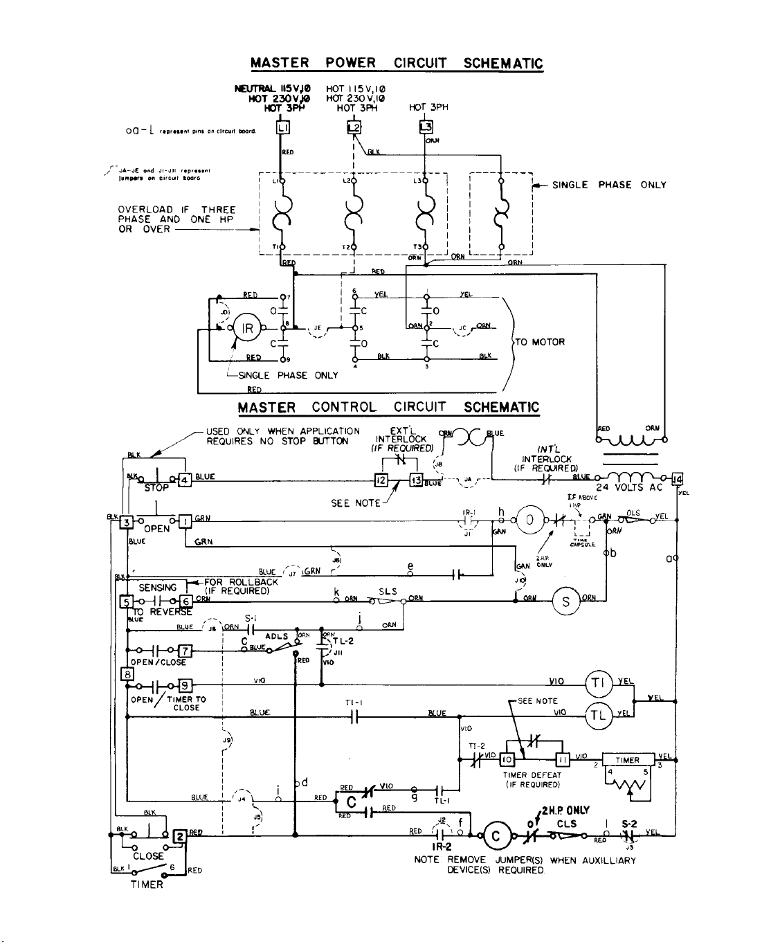
WIRING
TYPE
COMMERCIAL DOOR OPERATOR
LISTED
Page 2

VOLTAGE/PHASE
SINGLE
PH
JUMPERS
& RELAYS
JA X
JB X X
JC X X X X
JE X X
J1 X X X
J2 X X X
120V LR RELAY X
240V IR RELAY X
INLINE OVERLOAD X X
TIME CAPSULE*** X
* OPTIONAL ADJUSTABLE TIMER FUNCTION
AVAILABLE TO ACTIVATE WARNING SYSTEM
PRIOR TO AUTOMATIC DOOR CLOSING
(REQUIRES 115V POWER SOURCE IF
OPERATOR IS NOT 115 VOLT.)
** MOTORS AT THESE RATINGS ARE SUPPLIED
AS STANDARD WITH AN INTERNAL,
AUTOMATIC RESETTING OVERLOAD. (IN LINE
OVERLOADS ARE OPTIONAL)
X X
**
THREE
PH
X X
JUMPER CHART
JUMPERS,
RELAYS
SWITCHES &
TIMERS
J3
J4
J6
J7
J8
J9
J10
J11
SENSING LIMIT
AUX DEVICE
LIMIT
TIMER IMPULSE
RELAY
TIMER LATCHING
RELAY
TIMER
3 BUTTON
STATION
2 BUTTON
STATION
1 BUTTON
STATION
WIRING TYPES * * * *
B C D E B1 C1 D1 B2 C2 E2 S T ST TS STS
X X X X
X X X X X X X X
X X X X X X X
X X
X X X X X X X X X X X X X
X X X X X X X X
X X X
X X X X X X X X X
X X
X X X X X X X X X X X X
X X X X X X X X X X X
X X X X X X
X X X X
X X X X
X X X X
X X X X X X X X
X X X X
X X X
*** L5 SEC. DELAY TO OPEN TIME CAPSULE
ALLOWS LARGE DOORS TIME TO SETTLE
DOWN BEFORE REVERSING TO OPEN
POSITION.
NOTE: ELECTRIC EYES AND LOOP
DETECTORS ARE NOT TO BE USED AS
SENSING DEVICES TO STOP OR REVERSE
WHEN TS OR STS WIRING TYPES ARE USED.
OVERLOAD AND CAPACITOR VALUES
SINGLE PHASE THREE PHASE
OVERLOAD VALUES CAPACITOR VALUES OVERLOAD VALUES
115 VOLT
HP AMP PART
1/3
7
1/2 10 452433 5 452430 3781 15 452434 8 452432 3782
- - - - - - - -
3
- - - - - - - -
NO.
452431 3.5 452429 378-
230 VOLT CENTURY FRANKLIN 230 VOLT 460 VOLT
MFD/VAC PART
NO.
MFD/VAC PART
NO.
453212 386-
455/125
453212 386-
455/125
453212 431-
455/125
MOTOR REPLACEMENT
HP 1 PHASE 3 PHASE
AMP PART
NO.
453213 2.20** 453377 1.00** 453375
464/110
453213 2.60 453377 1.40 453375
464/110
453214 4.00 453378 1.95 453376
518/110
PART NUMBER
AMP PART NO.
6.20 453380 3.20 453378
10.50 458001 5.20 453380
AMP
PART
NO.
1/3 451347 451350
1/2 451348 451351
1 451349 451352
2 -------- 451353
Page 3

TYPE STATION NUMBER FUNCTION
B 3 Button 453365 Momentary contact to open, close and stop.
B1 3 Button 453639 Momentary contact to open, close and stop plus wiring for sensing
device to stop.
B2 3 Button 453642 Momentary contract to open, close and stop plus wiring for sensing
device to reverse and auxiliary devices to open and close with
override.
C 3 Button 453636 Momentary contact to open and stop with constant pressure to
close.
C1 3 Button 453640 Momentary contact to open and stop with constant pressure to close
and wiring for sensing device to stop.
C2 3 Button 453643 Momentary contact to open and stop with constant pressure to
close.
D 2 Button 453641 Constant pressure to open and close.
D1 2 Button 453641 Constant pressure to open and close with wiring for sensing device
to stop.
E 2 Button 453638 Momentary contact to open and constant pressure to close. Release
of close button will cause door to reverse (rollback feature).
E2 2 Button 453644 Momentary contact to open with open override and constant
pressure to close.
S 1 Button 453645 Momentary contact to open and close plus wiring for sensing device
to reverse, auxiliary devices to open and close, with open override.
T 3 Button 453646 Momentary contact to open, close and stop with open override and
timer to close. Open button may be connected to activate timer if
desired. Auxiliary controls may be connected to open and activate to
close or to open and close, without activating timer.
ST 1 Button 453647 “T” type wiring with single button instead of three button operation.
(See “S” type wiring.)
TS 3 Button 453648 momentary contact open, close and stop with open override and
timer to close. EVERY device that causes door to open will activate
timer to close including sensing device to reverse. Timer may be
deactivated until next opening signal is received by depressing stop
button after door has reached open position or permanently by use
of optional timer defeat switch. Photo-cell or loop detector not
recommended for use as a sensing device to reverse with this wiring
type.
STS 1 Button 453649 ‘TS” type wiring with single button instead of three button operation.
(See ‘S” type wiring.)
Notes: 1. External interlocks may be wired into all wiring types.
2. Auxiliary devices are any devices that have only one set of contacts.
Examples are: photo-cell, loop detector, pneumatic or electric treadles,
residential radio controls, one button stations, pull cords\, etc.
3. open override means that the door may be reversed while closing by
activating an opening device without the need to use the step button first.
Page 4
Page 5

Page 6

MOTOR WIRING DIAGRAMS
1 PHASE
114A1039 1987, The Chamberlain Group, Inc
Rights Reserved Printed in Mexico
Page 7

CONTROL CONNECTION DIAGRAM
Page 8

ILLUSTRATED PARTS BREAKDOWN
6
Page 9

1
1
1
/
/
2
O
E
P
R
A
T
O
R
ITEM PT.NO. DESCRIPTION QUANTITY
A 451348 Motor 1/2 HP. 115V 1 Phase 1
451348 Motor 1/2 HP. 230V 1 Phase 1
451351 Motor 1/2 HP. 230V 3 Phase 1
451351 Motor 1/2 HP. 460V 3 Phase 1
451349 Motor 1 HP. 115V 1 Phase 1
451349 Motor 1 HP. 230V 1 Phase 1
451352 Motor 1 HP. 230V 3 Phase 1
451352 Motor 1 HP. 460V 3 Phase 1
451353 Motor 2 HP. 230V 3 Phase 1
451353 Motor 2 HP. 460V 3 Phase 1
B 450337 Reducer 1/2 & 1 HP. 1 1 1 1 1 1 1 1 1 1
450338 Reducer, 2 HP. 1 1
C Electric Box, basic w/P.C.B. See Detail
D 451276 Cover, Electric Box 1 1 1 1 1 1 1 1 1 1
E 93C99 GJ Hoist/Brake Housing 1 1 1 1 1 1 1 1 1 1
F 454034 Cover, GJ Hoist Brake Hsg. 1 1 1 1 1 1 1 1 1 1
G 454227 Brake Disc-Gearhead Assy. 1 1 1 1 1 1 1 1 1 1
H 450592 Reducer Bevel Gear 1 1 1 1 1 1 1 1 1 1
I 450593 Chain Bevel Gear 1 1 1 1 1 1 1 1 1 1
J 450701 Brake 1 1 1 1 1 1 1 1 1 1
K 450330 Brake Cam 1 1 1 1 1 1 1 1 1 1
L 454004 Brake Arm 1 1 1 1 1 1 1 1 1 1
M 450218 Brake Solenoid 115V 1 1
450219 Brake Solenoid 230V & 460V 1 1 1 1 1 1 1 1
N 454020 Lever, Auxiliary Operation 1 1 1 1 1 1 1 1 1 1
O 12B390 Mounting Bracket ‘B’ 2 2 2 2 2 2 2 2 2 2
P 12B389 Mounting Bracket ‘A’ 2 2 2 2 2 2 2 2 2 2
Q 450172 Shaft, Hand Chain 1 1 1 1 1 1 1 1 1 1
R 454339 Emergency Cable Assembly 1 1 1 1 1 1 1 1 1 1
S 453022 Limit Protector 1 1 1 1 1 1 1 1 1 1
T 450230 Limit Switch 1 1 1 1 1 1 1 1 1 1
U 453117 Cable Guide 1 1 1 1 1 1 1 1 1 1
V 451615 Disconnect Spring 1 1 1 1 1 1 1 1 1 1
W 454005 Spacer, Chain Guide 1 1 1 1 1 1 1 1 1 1
X 450236 Cable Clamp, 90º-#/8” 1 1 1 1 1 1 1 1 1 1
Y 453105 Set Collar, 3/4” 4 4 4 4 4 4 4 4 4 4
Z 452219 Flange Blushing, w/Key, 3/4” 2 2 2 2 2 2 2 2 2 2
AA 451888 Lmt. Chain 51P.1/2& HP w/o Link 1 1 1 1 1 1 1 1
451889 Limit Chain 53P. 2 HP w/o Link 1 1
2
H
H
P
P
1
2
1
3
5
0
V
V
1
1
P
P
H
H
A
A
S
S
E
E
1
/
/
1
1
1
1
2
2
H
H
H
H
P
P
P
2
4
3
0
V
3
P
H
A
S
E
1
6
1
0
5
V
V
3
1
P
P
H
H
A
A
S
S
E
E
H
P
P
2
2
3
3
0
0
V
V
1
3
P
P
H
H
A
A
S
S
E
E
2
H
H
P
P
4
2
6
3
0
0
V
V
3
3
P
P
H
H
A
A
S
S
E
E
* SPROCKET SIZE VARIES WITH DOOR TYPE. SPROCKET CAN BE USED ON
EITHER END OF SHAFT.
2
H
P
4
6
0
V
3
P
H
A
S
E
Page 10

1
1
1
/
/
2
O
E
P
R
A
T
O
R
ITEM PT.NO. DESCRIPTION QUANTITY
BB 451850 Master Link #65 1 1 1 1 1 1 1 1 1 1
CC 450574 Sprocket 43-B-14x1” 1 1 1 1 1 1 1 1 1 1
DD 451620 Spring, Brake 1 1 1 1 1 1 1 1 1 1
EE 453109 Set Collar 1/8” 1 1 1 1 1 1 1 1 1 1
FF 452032 Set Screw 5/16-18x1/4” 6 6 6 6 6 6 6 6 6 6
GG 453119 Roll Pin 3/16x1-1/4” 2 2 2 2 2 2 2 2 2 2
HH 453104 Eye Bolt 5/16, 10-24x1-3/8” 1 1 1 1 1 1 1 1 1 1
II 232124 Cotter Pin 3/16x1-1/2” 1 1 1 1 1 1 1 1 1 1
JJ 453118 Hair Cotter Pin 1 1 1 1 1 1 1 1 1 1
KK 451421 Woodruff Key, 3/16x3/4” 1 1 1 1 1 1 1 1 1 1
LL 450420 Key, 3/16x3/16x1-1/8” 1 1 1 1 1 1 1 1 1 1
MM 452098 Rd. Hd. Mach. Screw 1/4-20x2” 1 1 1 1 1 1 1 1 1 1
NN 230707 Bolt, Hex Head 1/4-20x3/4” 4 4 4 4 4 4 4 4
452063 Bolt, Hex Head 1/4-20x1-1/4” 4 4
OO 452085 Screw Hex Head 5/16-18x2” 2 2 2 2 2 2 2 2 2 2
PP 230703 Screw, Hex Head 3/8-16x1” 4 4 4 4 4 4 4 4 4 4
QQ 452005 Screw Machine Rd. Hd. 4-40x5/8” 2 2 2 2 2 2 2 2 2 2
RR 452033 Scre, Sheet Metal #6x3/8 4 4 4 4 4 4 4 4 4 4
SS 452097 Lock Nut 1/4-20 1 1 1 1 1 1 1 1 1 1
TT 230303 Nut, Hex 1/4-20 1 1 1 1 1 1 1 1 1 1
UU 230612 Washer, Lock - Internal Tooth #4 2 2 2 2 2 2 2 2 2 2
VV 230601 Washer, Lock - Split 3/8” 4 4 4 4 4 4 4 4 4 4
WW 230311 Nut, hex 10-24 2 2 2 2 2 2 2 2 2 2
XX 452076 Lock Nut 5/16-18 2 2 2 2 2 2 2 2 2 2
ZZ 290230 Washer, Bronze 3/4”x.020 1 1 1 1 1 1 1 1 1 1
AAA 454337 Chain Guide 1 1 1 1 1 1 1 1 1 1
BBB 450926 Chain Wheel 1 1 1 1 1 1 1 1 1 1
CCC 350104 Hand Chian, 910 1 1 1 1 1 1 1 1 1 1
DDD 571302 Chain Keeper 1 1 1 1 1 1 1 1 1 1
EEE * Sprocket, Drive Shaft 1 1 1 1 1 1 1 1 1 1
FFF 450425 Washer, Steel 3/4”x.020 2 2 2 2 2 2 2 2 2 2
GGG 450419 Key, 1/4x1/4x1” 2 2 2 2 2 2 2 2 2 2
HHH 451774 Wiring Cable Assembly, Brake 1 1 1 1 1 1 1 1 1 1
III 230602 Lockwasher, 1/4” Split 4 4 4 4 4 4 4 4 4 4
JJJ 453035 Bushing, Straight-Thru, 5/8” 1 1 1 1 1 1 1 1 1 1
KKK 171A334 Screw, Type F - #8-32x3/8” <---------------- 10 ---------------->
LLL 171A333 Screw, Type F - #6-32x3/8” 2 2 2 2 2 2 2 2 2 2
MMM 450252 Cable Tie 1 1 1 1 1 1 1 1 1 1
2
H
H
P
P
1
2
1
3
5
0
V
V
1
1
P
P
H
H
A
A
S
S
E
E
1
/
/
1
1
1
1
2
2
H
H
H
H
P
P
P
2
4
3
0
V
3
P
H
A
S
E
1
6
1
0
5
V
V
3
1
P
P
H
H
A
A
S
S
E
E
H
P
P
2
2
3
3
0
0
V
V
1
3
P
P
H
H
A
A
S
S
E
E
2
H
H
P
P
4
2
6
3
0
0
V
V
3
3
P
P
H
H
A
A
S
S
E
E
2
H
P
4
6
0
V
3
P
H
A
S
E
* SPROCKET SIZE VARIES WITH DOOR TYPE. SPROCKET CAN BE USED ON
EITHER END OF SHAFT.
Page 11

10
9
Page 12

G
1
1
1
J
/
/
2
E
L
E
C
T
R
I
C
A
L
B
O
X
ITEM PT.NO. DESCRIPTION QUANTITY
A 453020 P.C. Board, Option - Commercial 1 1 1 1 1 1 1 1 1 1
B 453021 Contractor, S/D 1 1 1 1 1 1 1 1
C 453336 Switch, Limit - Open, Wired 1 1
D 453339 Switch Limit - Closed, Wired 1 1 1 1 1 1 1 1 1 1
E 453335 Assembly, Motor Cable 1 1 1 1 1 1 1 1 1 1
F 451278 Box, Electrical - P.C.B. 1 1 1 1 1 1 1 1 1 1
G 453115 Standoff 4 4 4 4 4 4 4 4 4 4
H 452077 Nut Lock 8-32 2 2 2 2 2 2 2 2 2 2
I 450587 Nut Limit - Plastic, 1/2x20 2 2 2 2 2 2 2 2 2 2
J 452078 Screw, Sheet Metal - Grn. (Gnd) 1 1 1 1 1 1 1 1 1 1
K 452033 Screw, Sheet Metal #6x3/8” 2 2
L 450252 Wire Ties 3/32” 3 3 3 3 3 3 3 3 3 3
M 450229 Terminal, Double Male 1/4” 5 5 5 5 5 5 5 5 5 5
N 452094 Screw, Sheet Metal 12-24x1/2” 2 2 2 2 2 2 2 2 2 2
O 230612 Washer, Lock #4 Internal Tooth 8 8 8 8 8 8 8 8 8 8
P 453332 Assy. Wire 22 GA. Green (Gnd) 1 1 1 1 1 1 1 1 2 2
Q 452036 Cable Clamp 90º-3/8” 1 1 1 1 1 1 1 1 1 1
R 453393 Timer, Delayed Open 1 1
S 452073 Nut, Hex 6-32x1/2” 2 2
T 452074 Screw, Rd. Hd. 6-32x1/2” 2 2
U 452096 Washer, lock - Split #6 2 2
V 453376 Assembly, Overload 1.95A, 3 Phase 1
453378 Assy., Overload 4.0/3.2A, 3 Phase 1 1
453380 Assembly, Overload 6.2A, 3 Phase 1
453358 Assembly, Overload 10.0A, 1 Phase 1
453355 Assembly, Overload 5.0A, 1 Phase 1
453359 Assembly, Overload 15.0A, 1 Phase 1
453357 Assembly, Overload 8.0A, 1 Phase 1
2
H
H
P
P
1
2
1
3
5
0
V
V
1
1
P
P
H
H
A
A
S
S
E
E
1
/
/
1
1
1
1
2
2
H
H
H
H
P
P
P
2
4
3
0
V
3
P
H
A
S
E
1
6
1
0
5
V
V
3
1
P
P
H
H
A
A
S
S
E
E
H
P
P
2
2
3
3
0
0
V
V
1
3
P
P
H
H
A
A
S
S
E
E
2
H
H
P
P
4
2
6
3
0
0
V
V
3
3
P
P
H
H
A
A
S
S
E
E
2
H
P
4
6
0
V
3
P
H
A
S
E
Page 13

G
1
1
1
J
/
/
2
E
L
E
C
T
R
I
C
A
L
B
O
X
ITEM PT.NO. DESCRIPTION QUANTITY
W 452048 Screw Rd. Hd. 8-32x3/8” 2 2 2 2 2 2 2 2 2 2
X 453207 Assembly, Transformer 110V 1 1
453208 Assembly, Transformer 220V 1 1 1 1 1
453209 Assembly, Transformer 440 1 1 1
Y 453231 230V IR Relay 1 1
453232 115V IR Relay 1 1
Z 453247 Spring, IR Relay 1 1 1 1
AA 453037 Power Terminal Strip Guard 1 1 1 1 1 1 1 1 1 1
BB 230615 Lock Washer #8 External Tooth 1 1 1 1 1 1 1 1 1 1
2
H
H
P
P
1
2
1
3
5
0
V
V
1
1
P
P
H
H
A
A
S
S
E
E
1
/
/
1
1
1
1
2
2
H
H
H
H
P
P
P
2
4
3
0
V
3
P
H
A
S
E
1
6
1
0
5
V
V
3
1
P
P
H
H
A
A
S
S
E
E
H
P
P
2
2
3
3
0
0
V
V
1
3
P
P
H
H
A
A
S
S
E
E
2
H
H
P
P
4
2
6
3
0
0
V
V
3
3
P
P
H
H
A
A
S
S
E
E
2
H
P
4
6
0
V
3
P
H
A
S
E
LIMIT SWITCH ASSEMBLY
ITEM PT. NO. DESCRIPTION QUANTITY
100 171A335 Hex. Hd. Mach. Scr. #4-40x5/8” 4 4 4 4 4 4 4 4 4 4
101 450347 Spacer, Limit Switch 4 4 4 4 4 4 4 4 4 4
102 171A336 Hex Hd. Mach Scr. #4-40x5/16” 2 2 2 2 2 2 2 2 2 2
103 171A275 Hed Hd. Mach Scr. #8-32x3/4” 2 2 2 2 2 2 2 2 2 2
104 177A113 Spring Compression 2 2 2 2 2 2 2 2 2 2
105 450353 Bracket, L/S Mounting 1 1 1 1 1 1 1 1 1 1
106 450349 Retaining Ring 1 1 1 1 1 1 1 1 1 1
107 450350 Bearing, Flange 2 2 2 2 2 2 2 2 2 2
108 450179 Shaft Limit 1 1 1 1 1 1 1 1 1 1
109 450348 Sprocket, Limit Switch 1 1 1 1 1 1 1 1 1 1
110 171A338 Scr. Skt. Hd. Set #10-21x1/4 1 1 1 1 1 1 1 1 1 1
111 450352 Retainer, Travel Nut 1 1 1 1 1 1 1 1 1 1
112 171A337 Scr. Hex Hd. Mach #8-32x1/2” 4 4 4 4 4 4 4 4 4 4
113 452026 Washer, Split Lock #8 4 4 4 4 4 4 4 4 4 4
114 452003 Nut, Hex #8-32 4 4 4 4 4 4 4 4 4 4
 Loading...