

Page 1
OWNER'S MANUAL
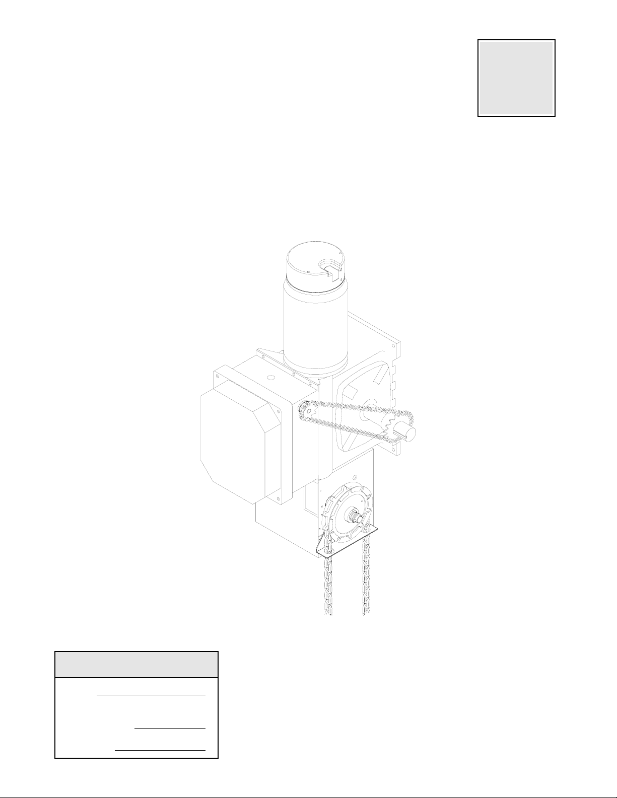
MODEL GH 5HP
HEAVY DUTY DOOR OPERATOR
Serial #
(located on electrical box cover)
Installation Date
Wiring Type
2 YEAR WARRANTY
FACTORY SET
C2 Wiring
See page 8 for
other wiring
configurations
Page 2
SPECIFICATIONS
MOTOR
TYPE:....................................AC Synchronous
continuous duty
brake motor
ENCLOSURE:.......................ODP NEMA 184TC face
mount.
HORSEPOWER:...................5 HP
Three phase
SPEED:.................................1725 RPM
VOLTAGE:.............................208/230 & 460 Three phase
OR 575V Three Phase
BRAKE HOLDING
FORCE:.................................15 Ft-Lbs
DRIVE SYSTEM
CONTINUOUS
POWER RATING: .................1000 Ft-Lbs/Sec
GEAR BOX:..........................Worm gear
LUBRICATION:.....................Oil Bath
RATIO: ..................................45:1
OUTPUT SPEED: .................38 rpm
DOOR SPEED: .....................5” per sec.
depending on door
OUTPUT SHAFT:..................1.5” Dia. with 3/8” keyway
OVERHUNG LOAD:..............1752 Lbs.
(1.5” from output bearing face)
HOIST WHEEL: ....................Standard mounting on
left or right side.
DISCONNECT:......................Floor level chain hoist with
electrical interlock for
emergency manual door
operation.
ELECTRICAL
TRANSFORMER:...............3PH: 208/230/480 VAC 24VAC
OR 3PH: 575VAC-24VAC
CONTROL STATION: ........NEMA 1 three button station.
OPEN/CLOSE/STOP
WIRING TYPE: ...................Standard C2 Wiring- Standard
operators are shipped from the factory set for C2 wiring,
which requires momentary contact to open, constant
pressure to close, stop on release.
Optional B2 Wiring- Which requires momentary contact to
open, close and stop. See schematic diagram on page 12
for instructions on how to configure the operator for B2
wiring
Wiring for sensing device to reverse and auxiliary devices to
open and close with open override.
LIMIT ADJUST: ..................Rotary driven, fully
adjustable screw type cams. Adjustable to 50 feet.
(Provides 2 minutes of operator running time).
DUTY CYCLE:....................25 Reversing cycles per hour
DELAY ON REVERSE:.......Standard
SAFETY
REVERSING EDGE:.......(Optional) Electric or pneumatic
sensing device attached to the bottom edge of door.
A REVERSING EDGE IS STRONGLY RECOMMENDED
ALL
FOR
REQUIRED
IS OUT OF SIGHT OF DOOR OR ANY OTHER
CONTROL (AUTOMATIC OR MANUAL) IS USED.
SHOULD THE CHAIN OR OPERATOR FAIL AS AN
ADDED SAFETY FEATURE, IT IS RECOMMENDED TO
USE STOP LOCK BEARINGS ON THE DOOR SHAFT
TO PREVENT THE DOOR FROM CRASHING DOWN.
COMMERCIAL OPERATOR INSTALLATIONS.
WHEN THE 3 BUTTON CONTROL STATION
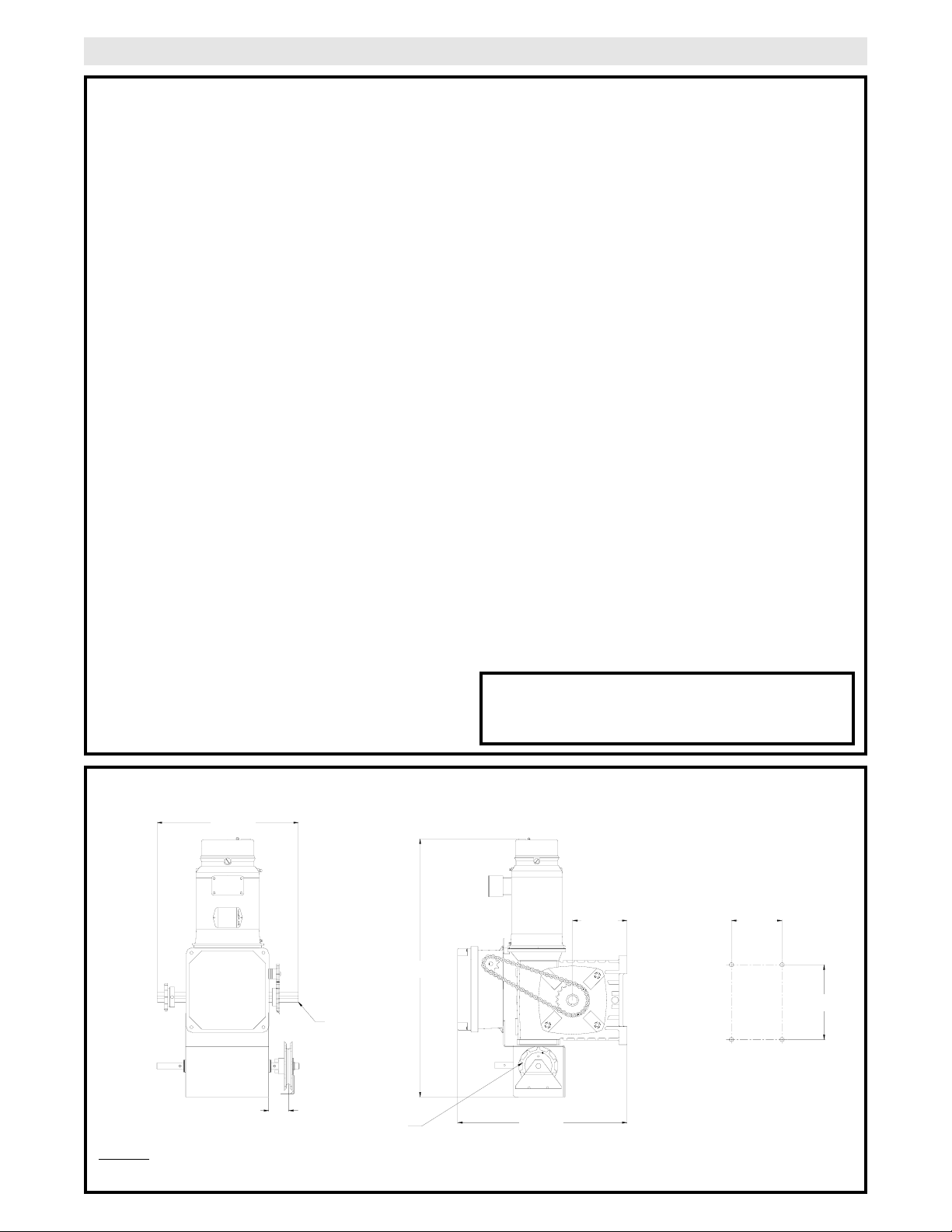
WEIGHTS AND DIMENSIONS
HANGING WEIGHT:.......300 LBS.
18.00”
See
Note #1
2.38”
Hand Chain Wheel
NOTES:
1) Output Shaft 1.5” Dia. with 3/8” Keyw a y.
40.25”
8.50”
26.38”
7.87”
11.61”
2
Page 3
TO AVOID DAMAGE TO DOOR AND OPERATOR,
MAKE ALL DOOR LOCKS INOPERATIVE. SECURE
LOCK(S) IN "OPEN" POSITION.
IF THE DOOR LOCK NEEDS TO REMAIN
FUNCTIONAL, INSTALL AN INTERLOCK SWITCH.
DO NOT CONNECT ELECTRIC POWER UNTIL
INSTRUCTED TO DO SO.
KEEP DOOR BALANCED. STICKING OR BINDING
DOORS MUST BE REPAIRED. DOORS, DOOR
SPRINGS, CABLES, PULLEYS, BRACKETS AND
THEIR HARDWARE MAY BE UNDER EXTREME
TENSION AND CAN CAUSE SERIOUS PERSONAL
INJURY. CALL A PROFESSIONAL DOOR
SERVICEMAN TO MOVE OR ADJUST DOOR
SPRINGS OR HARDWARE.
WARNING
CAUTION
WARNING
WARNING
WARNING
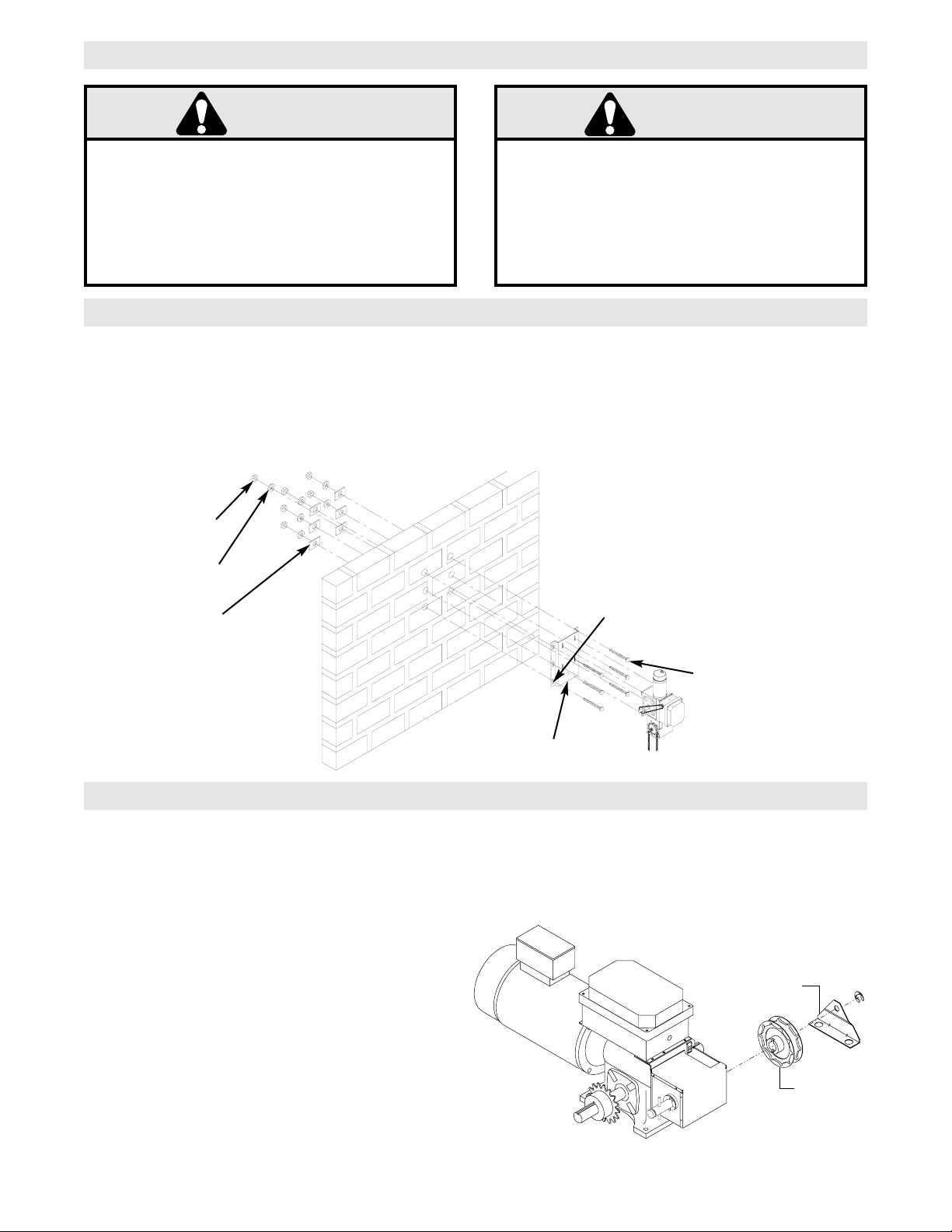
SITE PREPARATIONS
It is imperative that the wall or mounting surface
provide adequate support for the operator.
This surface must:
a) Be rigid to prevent play between operator and
door shaft.
b) Provide a level base.
OPERATOR PREPARATION
IMPORTANT SAFETY NOTES
The GH operator may be mounted on either the right (standard) or left side of door, and in either a vertical
(standard) or horizontal mounting position. Refer to the steps below if you require the hand chain and/or
disconnect chain to be on the opposite side of the operator; Or if the operator is being mounted in a horizontal
position.
Hand Chain Right/Left Conversion
Remove the outer snap ring securing the chain wheel
assembly. In reverse of disassembly, install the chain
wheel assembly on the opposite side of the gear hoist
housing.
FIGURE 2
c) Permit the operator to be fastened securely and
with the drive shaft parallel to the door shaft.
The safety and wear of the operator will be adversely
affected if any of the above requirements are not met.
FIGURE 1
BEARING PLATES
RECOMMENDED MIN. SIZE
1/4” THK. 2” X 2” SQ. MIN.
STEEL
OPTIONAL
MOUNTING PLATE
(SEE PAGE 16)
USE 5/8” DIA. BOLTS THAT
PROTRUDE THROUGH THE
WALL, WITH BEARING PLATES
ON THE OUTSIDE OF THE
BUILDING TO DISPLACE THE
LOAD.
5/8” DIA. BOLT
HEX NUT
LOCK WASHER
CAUTION
WARNING
Chain Guide
Hand
Chain Wheel
Page 4
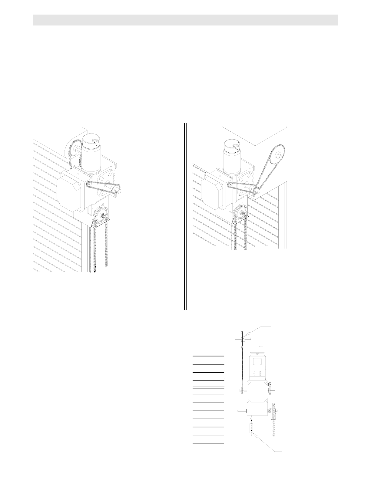
OPERATOR MOUNTING
Before your operator is installed, be sure the door has been properly aligned and is working smoothly. The
operator may be wall mounted or mounted on a bracket or shelf. If necessary, refer to the operator preparations
on page 3. Refer to the illustration and instructions below that suits your application. NOTE: The operator has a
weight of 300 lbs.
1a. Wall Mounting
The operator should generally be installed below
the door shaft, and as close to the door as
possible. Refer to Figure 3.
1b. Bracket or Shelf Mounting
The operator may be mounted either above or
below the door shaft. Refer to Figure 4.
Typical Right Hand
Wall Mounted Operator
FIGURE 3
1c. Place door sprocket on the door shaft. Do not
insert the key at this time.
2. Place drive sprocket on the appropriate side of
the operator. Do not insert the key at this time.
3. Wrap drive chain around door sprocket and join
roller chain ends together with master link.
4. Raise operator to approximate mounting position
using suitable lifting apparatus and position chain
over operator sprocket.
5. Raise or lower operator until the chain is taut (not
tight). Make sure the operator output shaft is
parallel to door shaft and sprockets are aligned.
When in position, secure the operator to wall or
mounting bracket.
6. Align sprockets and secure, (see Figure 5).
IMPORTANT:
provide adequate support, prevent play
between operator and door shaft, and permit
operator to be fastened securely and with the
drive shaft parallel to the door shaft.
The shelf or bracket must
FIGURE 4
Be sure door
sprocket is properly
aligned with drive
before securing to
the shaft.
Chain Keeper
FIGURE 5
4
Page 5

This operator is equipped with a manual hoist. An
electrical interlock will disable the electrical controls
when the hoist is used.
To operate the hoist:
1. Pull the disconnect chain (small chain) to engage
the hoist mechanism. The disconnect chain may be
locked in position by slipping the end through the
keyhole of the chain keeper mounted on the wall.
2. Operate the door in the desired direction by pulling
on one side or the other of the continuous loop hoist
chain (large chain).
3. The disconnect chain must be released from the
chain keeper before the door will operate again
electrically.
5
7. Install Hand Chain Place hand chain around hand chain wheel. Be
sure to pass it through both openings in the chain
guide. Remove enough links so chain hangs
approximately two feet above the floor
8. Mount Chain Keeper / Keyhole Bracket Using suitable hardware mount the chain keeper approximately 4 feet above the floor, near the free hanging chain. Remove disconnect sash chain from bag. Install locking collar onto the disconnect chain. Place end through the keyhole in the chain keeper. With the disconnect chain having no slack slide collar up 3” from keyhole in the chain keeper and lock into place by tightening the set screw. Confirm that when the sash chain is pulled, the locking collar is against the chain keeper and at the same time, the bevel gears located in the operator hoist mechanism are in full engagment. If not then readjust the collar to assure full engagment. Remove excesss links if necessary.
EMERGENCY MANUAL OPERATION
This operator has provisions for manually operating the door in case of emergency or power failure.
Model GH 5HP
Chain Keeper
(with pad locking provisions)
Manual Hoist
TURN OFF POWER TO THE OPERATOR BEFORE
MANUALLY OPERATING YOUR DOOR.
WARNING
Released Position
Engaged Position
3”
COLLAR
12-14737
WARNING
Page 6
WARNING
ENTRAPMENT PROTECTION ACCESSORIES (OPTIONAL)
SENSING EDGES
All types of sensing edges with an isolated normally
open (N.O.) output are compatible with your operator.
This includes pneumatic and electric edges. If your
door does not have a bottom sensing edge and you
wish to purchase one, contact the supplier of your
operator.
If not pre-installed by the door manufacturer, mount
the sensing edge on the door according to the
instructions provided with the edge. The sensing
edge may be electrically connected by either coiled
cord or take-up reel. Refer to the steps below.
Important Notes:
a) Proceed with Limit Switch Adjustments before
making any sensing edge wiring connections to
operator as described below.
b) Electrician must hardwire the junction box to the
operator electrical box in accordance with local
codes.
IT IS STRONGLY RECOMMENDED THAT A
SENSING EDGE OR OTHER ENTRAPMENT
PROTECTION DEVICE BE USED IN
CONJUNCTION WITH THIS OPERATOR.
WIRING:
For wiring of your sensing device to the operator,
refer to the schematic diagram supplied with your
operator. See field connection terminals identified
as Sensing Device or Safety Edge.
TAKE-UP REEL: Take-up reel should be installed
12" above the top of the door.
COIL CORD: Connect operator end of coil cord to
junction box (not supplied) fastened to the wall
approximately halfway up the door opening.
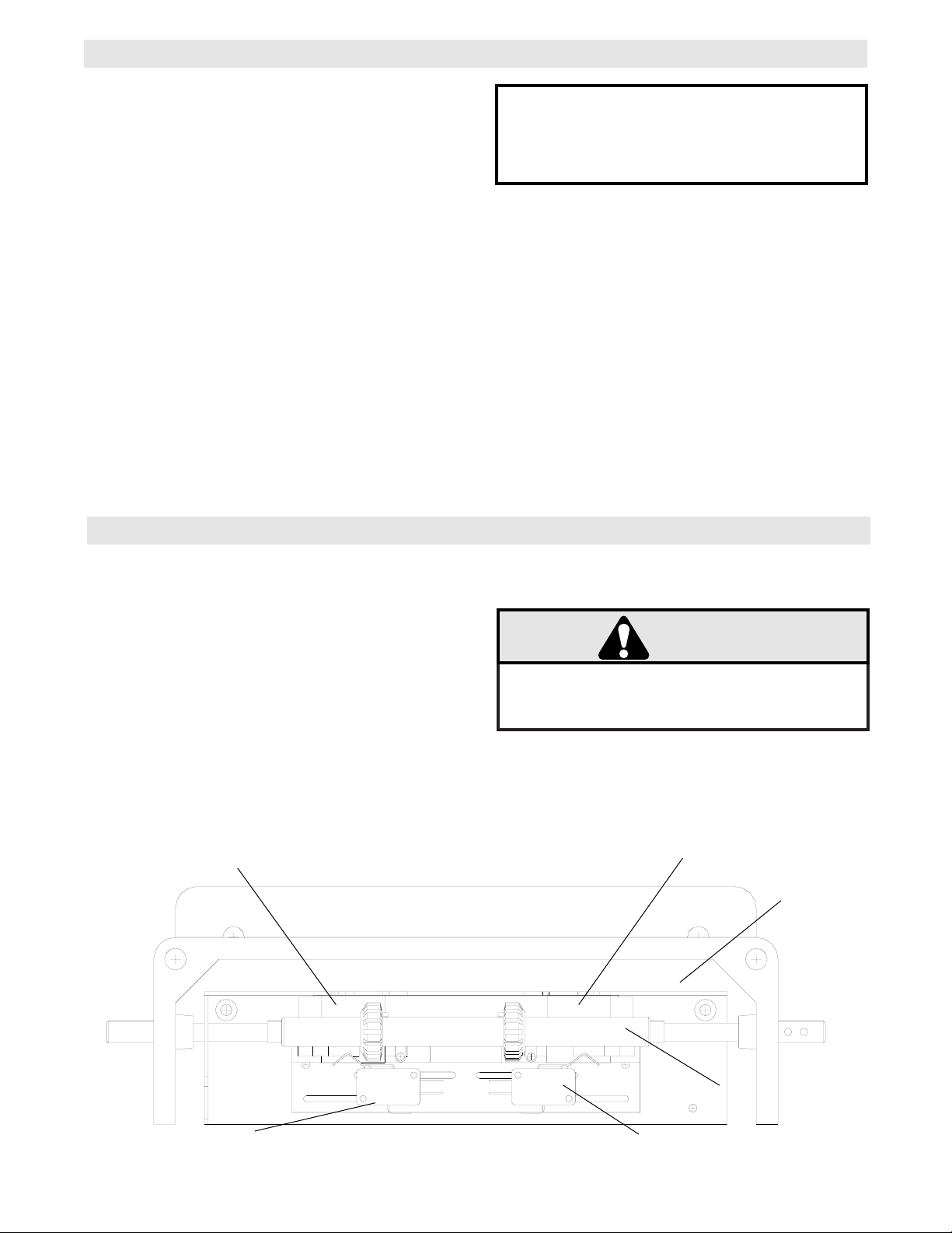
LIMIT SWITCH ADJUSTMENT
MAKE SURE THE LIMIT NUTS ARE POSITIONED BETWEEN THE LIMIT SWITCH ACTUATORS BEFORE
PROCEEDING WITH ADJUSTMENTS.
1. To adjust limit nuts depress retaining plate to allow
nut to spin freely. After adjustment, release plate
and ensure it seats fully in slots of both nuts.
2. To increase door travel, spin nut away from
actuator. To decrease door travel, spin limit nut
toward actuator.
3. Adjust open limit nut so that door will stop in open
position with the bottom of the door even with top
of door opening.
4. Repeat Steps 1 and 2 for close cycle. Adjust close
limit nut so that actuator is engaged as door fully
seats at the floor.
CLOSE Limit Switch
WARNING
TO AVOID SERIOUS PERSONAL INJURY OR DEATH
FROM ELECTROCUTION, DISCONNECT ELECTRIC
POWER BEFORE MANUALLY MOVING LIMIT NUTS.
If other problems persist, call our toll-free number for
assistance - 1-800-528-2806.
OPEN Limit Switch
Actuator
SAFETY
(Aux. Close) Limit Switch
Retaining Plate
Aux. OPEN Limit Switch
6
Page 7

Remove the cover from the electrical enclosure. Inside this enclosure you will find the wiring diagram(s)
for your unit. Refer to the diagram (glued on the inside of the cover) for all connections described below.
If this diagram is missing, call the number on the back of this manual. DO NOT INSTALL ANY WIRING OR
ATTEMPT TO RUN THIS OPERATOR WITHOUT CONSULTING THE WIRING DIAGRAM.
POWER WIRING CONNECTIONS
DISCONNECT POWER AT THE FUSE BOX BEFORE
PROCEEDING.
OPERATOR MUST BE PROPERLY GROUNDED AND
PERMANENTLY WIRED IN ACCORDANCE WITH
LOCAL ELECTRICAL CODES. NOTE: THE
OPERATOR SHOULD BE ON A SEPARATE FUSED
LINE OF ADEQUATE CAPACITY.
ALL ELECTRICAL CONNECTIONS MUST BE MADE
BY A QUALIFIED INDIVIDUAL.
WARNING
TO AVOID DAMAGE TO DOOR AND OPERATOR,
MAKE ALL DOOR LOCKS INOPERATIVE. SECURE
LOCK(S) IN "OPEN" POSITION.
IF THE DOOR LOCK NEEDS TO REMAIN
FUNCTIONAL, INSTALL AN INTERLOCK SWITCH.
1. Be sure that the power supply is of the correct
voltage, phase, frequency, and amperage to supply
the operator. Refer to the operator nameplate on the
cover, and motor nameplate.
2. Recommended conduit entrance to be 7/8”
Dia. to be drilled by installer. Take care not to
damage the internal components, see below. Bring
supply lines to the operator and connect wires to the
terminals indicated on the WIRING CONNECTIONS
DIAGRAM.
DO NOT TURN POWER ON UNTIL YOU HAVE
FINISHED MAKING ALL POWER AND CONTROL
WIRING CONNECTIONS AND HAVE COMPLETED
THE LIMIT SWITCH ADJUSTMENT PROCEDURE.
IMPORTANT: THIS UNIT MUST BE PROPERLY
GROUNDED. A GROUND SCREW IS SUPPLIED IN
THE ELECTRICAL BOX FOR CONNECTION OF
THE POWER SUPPLY GROUND WIRE. FAILURE
TO PROPERLY GROUND THIS UNIT COULD
RESULT IN ELECTRIC SHOCK AND SERIOUS
INJURY.
POWER WIRING
WARNING
Do Not Run Power &
Control Wiring in the
Same Conduit
Recommended location for
7/8” Dia Holes for
power wiring conduit access
WARNING
WARNING
Page 8

CONTROL WIRING THREE PHASE FIELD WIRING
WARNING
CLOSE
DETERMINE WIRING TYPE
Refer to the wiring diagram located on the inside cover the electrical box to determine the type of control wiring.
Standard C2 or B2 Wiring
Standard operators are shipped from the factory with
jumper set for C2 wiring, which requires constant
pressure on button to close the door. If momentar y
contact on close direction is desired (B2 wiring) you
must include an entrapment protection device. See
close control jumper setting below.
Constant pressure on close (C2 wiring)
Red jumper wire was placed on terminal #2 in
electrical enclosure. The operator will require
constant pressure on close control in order to keep
door moving in the close direction.
Momentary contact on close (B2 wiring)
Move red jumper wire from terminal #2 to terminal
#3. The operator will require only momentary
contact to close the door.
SPECIAL CONTROL WIRING
If your operator was shipped from the factory with
non-standard control wiring or with optional
accessories that require addition instructions, refer to
the wiring diagram(s) indicated in the special control
wiring data box. When a replacement wiring diagram
is present, wiring diagrams in this manual will not
apply. Refer only to the replacement wiring diagram
for all connections.
IMPORTANT NOTE: If your wiring diagram is
missing, or you are unsure of the wiring type for
your operator, contact the customer service
department @ 1-800-528-2806.
LOCATING THE CONTROL STATION
All operators are supplied with some type of control station. Generally a three button station
(OPEN/CLOSE/STOP) is provided. A two-position key switch or control station (OPEN/CLOSE) may be added or
substituted when requested at the time of order. Mount the control station near the door.
MOUNT WARNING NOTICE
WARNING
INSTALL THE CONTROL STATION WHERE THE
DOOR IS VISIBLE, BUT AWAY FROM THE DOOR AND
ITS HARDWARE. IF CONTROL STATION CANNOT BE
INSTALLED WHERE DOOR IS VISIBLE, OR IF ANY
DEVICE OTHER THAN THE CONTROL STATION IS
USED TO A CTIVATE THE DOOR,
MUST
DOOR.
UNDER THESE CIRCUMSTANCES MAY RESULT IN
SERIOUS INJURY OR DEATH TO PERSONS
TRAPPED BENEATH THE DOOR.
BE INSTALLED ON THE BOTTOM OF THE
FAILURE TO INSTALL A REVERSING ED GE
A REVERSING EDGE
IMPORTANT: Mount WARNING NOTICE beside or
below the push button station.
Control Station
OPEN
Push
Buttons
C
STOP
LO
S
E
WARNING
TO PREVENT ENTRAPMENT
DO NOT START DOOR DOWNWARD
UNLESS DOORWAY IS CLEAR
WARNING Notice
8
Page 9

9
CONTROL WIRING (con’t)THREE PHASE SCHEMATIC DIAGRAM
Radio Controls
On all models with type B2 control wiring, a terminal
block marked R1 R2 R3 is located in the inside of the
electrical enclosure. All standard radio control
receivers may be used. The operator will then open a
fully closed door, close a fully open door, and reverse
a closing door from the radio transmitter. However, for
complete door control from a transmitter, a
commercial three-channel radio set (with connections
for OPEN/CLOSE/STOP) is recommended.
Additional Access Control Equipment
Locate any additional access control equipment as desired (but so that the door will be in clear sight of the person
operating the equipment), and connect to the terminal block in the electrical enclosure as shown on the FIELD
WIRING CONNECTIONS diagram. Any control with a normally (N.O.) isolated output contact may be connected
in parallel with the OPEN button. More than one device may be connected in this manner. Use 16 gauge wire or
larger for all controls. DO NOT USE THE CONTROL CIRCUIT TRANSFORMER (24VAC) IN THE OPERATOR
TO POWER ANY ACCESS CONTROL EQUIPMENT OTHER THAN A STANDARD TYPE RADIO RECEIVER.
External Interlock Switch
The operator has a terminal connection for an external interlock switch. This switch must be a normally closed
(N.C.) two-wire device with a contact rating of at least 3 amps @ 24VAC. When such a switch is connected as
shown on the FIELD WIRING CONNECTIONS diagram, the control circuit will be disabled when the switch is
actuated, thereby preventing electrical operation of the door from the control devices.
WARNING
DO NOT USE RADIO CONTROLS WITH YOUR
OPERATOR UNLESS YOU HAVE INSTALLED
SOME TYPE OF ENTRAPMENT PROTECTION
DEVICE. THE USE OF RADIO CONTROLS
PRESENTS POTENTIAL HAZARDS DUE TO THE
USER’S ABILITY TO OPEN OR CLOSE THE
DOOR WHEN OUT OF SIGHT OF THE DOOR. IN
ADDITION, IF A SINGLE CHANNEL CONTROL IS
USED, THE USER WILL NOT BE ABLE TO STOP
THE DOOR FROM THE TRANSMITTER.
WARNING
Page 10

WARNING
CONNECT REVERSING EDGE DEVICE (OPTIONAL)
WARNING
WARNING
IF CONTROL STATION CANNOT BE INSTALLED WHERE
DOOR IS VISIBLE, OR IF ANY DEVICE OTHER THAN
THE CONTROL STATION IS USED TO ACTIVATE THE
DOOR,
THE BOTTOM OF THE DOOR.
REVERSING EDGE UNDER THESE CIRCUMSTANCES
MAY RESULT IN SERIOUS PERSONAL INJURY OR
DEA TH T O PERSONS TRAPPED BENEATH THE DOOR.
A REVERSING EDGE MUST BE INSTALLED ON
FAILURE TO INSTALL A
NOTICE:
This equipment has been tested and found to comply with the limits for a Class A digital
device, pursuant to Part 15 of the FCC Rules. These limits are designed to provide
reasonable protection against harmful interference when the equipment is operated in a
commercial environment. This equipment generates, uses, and can radiate radio
frequency energy and, if not installed and used in accordance with the instruction
manual, may cause harmful interference to radio communications. Operation of this
equipment in a residential area is likely to cause harmful interference, in which case the
user will be required to correct the interference at his own expense.
The operator has been pre-wired to accept
connection of a reversing edge device. Connect the
normally open contacts to terminals T4 and T8 on the
low voltage terminal block. A cut-off switch will deactivate the safety device during the last few inches of
the door's downward travel.
TEST THE SYSTEM
Turn on power. Test all controls and safety devices to
make sure they are working properly. It will be
necessary to refer back to page 6 for fine adjustment
of the limit switches.
IMPORTANT NOTES:
Do not leave operator power on unless all safety
and entrapment protection devices have been
tested and are working properly.
Be sure you have read and understand all Safety
Instructions included in this manual.
Be sure the owner or person(s) responsible for
operation of the door have read and understand
the Safety Instructions, know how to electrically
operate the door in a safe manner, and know how
to use the manual disconnect operation of the
door operating system.
WARNING
DO NOT PLACE HANDS OR TOOLS IN OR NEAR
THE OPERATOR WHEN THE POWER IS ON OR
WHEN TESTING CONTROL OR SAFETY
DEVICES. ALWAYS DISCONNECT POWER
BEFORE SERVICING OR ADJUSTING THE
OPERATOR.
10
Page 11

11
HOW TO ORDER REPAIR PARTS
OUR LARGE SERVICE ORGANIZATION
SPANS AMERICA
INSTALLATION AND SERVICE INFORMATION
ARE AVAILABLE 6 DAYS A WEEK
CALL OUR TOLL FREE NUMBER - 1-800-528-2806
HOURS 7:00 TO 3:30 p.m. (Mountain Std. Time)
MONDAY Through SATURDAY
WHEN ORDERING REPAIR PARTS
PLEASE SUPPLY THE FOLLOWING INFORMATION:
PART NUMBER DESCRIPTION MODEL NUMBER
ADDRESS ORDER TO:
THE CHAMBERLAIN GROUP, INC.
Electronic Parts & Service Dept.
6020 S. Country Club Road
Tucson, AZ 85706
MAINTENANCE SCHEDULE
Use SAE 30 Oil (Never use grease or silicone spray).
U Repeat ALL procedures.
Motor grease fitting to be greased every 12,000 Hrs. of Motor operation. Recommended grease for
standard service conditions is Polyrex EM (Exxon Mobile).
Inspect and service whenever a malfunction is observed or suspected.
CA UTION: BEFORE SERVICING, AL WAYS DISCONNECT OPERA T OR FR OM POWER SUPPLY.
Check at the intervals listed in the following chart.
EVERY EVERY EVERY
ITEM PROCEDURE 3 MONTHS 6 MONTHS 12 MONTHS
Drive Chain Check for excessive slack.
Check & adjust as required.
Lubricate.*
z U
Sprockets Check set screw tightness z U
Fasteners Check & tighten as required z U
Manual Disconnect Check & Operate z U
Bearings & Shafts Check for wear & lubricate z U
Page 12

WARNING
1942
12
Page 13

13
1942
Page 14

WARNING
REPAIR PARTS KITS – ELECTRICAL BOX
Below are replacement kits available for your operator. For replacement of electrical box, motor or brake components be sure
to match model number of your unit to kit number below to ensure proper voltage requirements. Optional modifications and/or
accessories included with your operator may add or remove cer tain components from these lists. Please consult a par ts and
service representative regarding availability of individual components of kits specified below. Refer to page 11 for all repair
part ordering information.
COMPLETE ELECTRICAL BOX KITS
Item
1
03-8224-D
2
03-ABDIN-4
3
10-10477-1
4
21-xxxx
5
24-24-1
6
24-264-4
7
25-xxxx
8
27-8002-D
9
35-204
10
42-114
11
44-18194
12
80-10054
13
82-HS10-06
14
82-PX08-04T
15
82-PX08-10T
16
82-WS08-06G
17
85-FW-10
18
85-LS-10
P/N
Description
Contactor
Din Rail
Electrical Panel (Reworked)
Transformer 230/460V 3 HP
24VAC DPDT Relay
24VDC DPDT Relay
(See Overloads)
Contact Block
Fuse 4 Amp 125V
Terminal Block, 14 Position
Enclosure 12 x 10 x 6
Washer, #8 Terminal
Screw, #10-32 x 3/8” Long
Screw, #8-32 x 1/4” Long
Screw, #8-32 x 11/16” Long
Screw, #8-32 x 3/8” Long
Flatwasher, #10
Lockwasher, #10
K74-18346 LIMIT SHAFT ASSEMBLY KIT
Item
L1
11-10480
L2
12-10481
L3
12-10483
L4
13-10024
L5
13-10516
L6
15-48B18AXX
L7
80-10026
L8
82-PX08-10T
L9
84-FN-08
L10
86-RP04-100
L11
87-E-038
P/N
Description
Limit Shaft
Flange Bearing
Bearing Seal, 3/8” I.D.
Limit Nut
Neoprene Gasket
Sprocket 48B18 x 3/8” Bore
Washer, Shim
Screw, #8-32
Nut , #8-32 Serrated Flange
Roll Pin, 1/8 DIA. x 1” Long
E Ring, 3/8”
Qty
1
1
1
1
1
1
1
2
1
1
1
1
4
8
6
2
4
4
Qty
1
2
2
2
2
1
32
4
4
1
2
Overloads
25-4018-D Overload Model GH5HP23M
25-4010-D Overload Model GH5HP43M
25-4008-D Overload Model GH5HP53M
Transformers
21-3460-1 Model GH5HP23M &
Model GH5HP43M
21-3575-1 Model GH5HP53M
Electrical Box Kits
74-17965 Model GH5HP23M
74-17966 Model GH5HP43M
74-18081 Model GH5HP53M
K72-18345 LIMIT SWITCH ASSEMBLY KIT
Item
10-10476
S1
10-10478
S2
10-12553
S3
18-10036
S4
23-10041
S5
31-12378
S6
82-PX04-12
S7
82-PX04-20
S8
82-PX06-16
S9
82-PX08-04T
S10
84-LH-06
S12
P/N
Description
Depress Plate
Aux. L/S Mtg. Bracket
Nut Plate, Switch
Spring, Depress Plate
Limit Switch
Standoff, Limit Switch
Screw, #4-40 x 3/4” Long
Screw, #4-40 x 1-1/2” Long
Screw, #6-32 x 1” Pan Hd Phillips
Screw, #8-32 x 1/4” Long
Locknut, #6-32 Nylon Hex
Qty
1
1
4
2
4
4
4
4
2
2
2
14 7
Page 15

15
ILLUSTRATED PARTS – ELECTRICAL BOX
Page 16

WARNING
REPAIR PARTS KITS – MODEL GH 5HP
Refer to the parts lists below for replacement kits available for your operator. If optional modifications and/or
accessories are included with your operator, cer tain components may be added or removed from these lists.
Individual components of each kit may not be available. Please consult a parts and service representative
regarding availability of individual components. Refer to page 11 for all repair part ordering information.
INDIVIDUAL PARTS
ITEM PART # DESCRIPTION QTY
1
09-17985
2
09-17986
3
09-17989
4
10-17940
5
10-17984
6
10-17988
7
10-17990
8
15-48B18TKK
9
15-100B15TKK
10
23-10916
11
32-17914-1
12
44-18194
32 Degree Stop Block
0 Degree Stop Block
Wedge
Elec. Box Mounting Bracket
Interlock Bracket
Housing-Gear Hoist
Cover Gear Hoist
Sprocket, 48B18 TKK
Sprocket, 100B15 TKK
SPDT Interlock Switch
Gear Reducer
Electrical Box
1
1
2
1
1
1
1
1
1
1
1
1
K09-17987-1 ENGAGEMENT LEVER ASSEMBLY
ITEM PART # DESCRIPTION QTY
L1
L2
L3
L4
L5
L6
09-17987-1
10-17983
12-18052
31-18054
80-10022
82-SH31-10S
Engagement Lever
Interlock Actuator
Radial Ball Bearing
Spacer
Shim Washer
Shoulder Bolt 3/8” Body x 5/8” Long
1
1
2
2
6
4
K75-18323 CHAIN WHEEL ASSEMBLY KIT
ITEM PART # DESCRIPTION QTY
C1
C2
C3
C4
C5
10-10882
12-10883
75-10884
80-10022
87-E-075
Hand Chain Guide
Nyliner Bearing
Chain Wheel Assembly
Shim Washer
E Ring, 3/4”
1
1
1
1
1
K75-13344 CHAIN ASSY/ BRAKE RELEASE KIT
ITEM PART # DESCRIPTION QTY
R1
R2
R3
R4
R5
R6
R7
18-18190
80-11646
80-1012
82-18077
84-FN31
85-FW-31
96-3575
Safety Draw-Bar Extension Spring
Double Sleeve
S-Hook
Hex Bolt-Modified
Hex Nut, Serrated Flange 5/16-18
Flat Washer For 5/16 Bolt
Braided Cable
1
2
2
1
1
1
1
OPTIONAL ACCESSORIES
PART # DESCRIPTION
50-18084 Mounting Bracket Kit
Motors
20-3500C-4B Model GH5HP23M &
Model GH5HP43M
20-3500C-5B Model GH5HP53M
K75-18324 HAND CHAIN SHAFT KIT
ITEM PART # DESCRIPTION QTY
H1
H2
H3
H4
H5
H6
H7
H8
H9
H10
H11
H12
08-17694-1
08-17695-1
11-18051
12-10029
18-9301
31-18053
80-10022
80-10026
86-DP06-104
86-RP08-112
86-RP10-208
87-E-075
Bevel Gear
Bevel Gear
Shaft
Flanged Bearing
Compression, Spring
Spacer
Shim Washer, .050 Thk.
Shim Washer, 3/8” I.D. x .010 Thk.
Dowel Pin 3/16 Dia. x 1.25 Long
Roll Pin, 1/4” x 1-3/4” Long
Roll Pin, 5/16” x 2-1/2” Long
E-Ring, 3/4”
K75-18180 MOTOR BRAKE ASSEMBLY KITS
ITEM PART # DESCRIPTION QTY
B1
B2
B3
B4
B5
B6
B7
B8
B9
B10
B11
B12
B13
10-17996
10-17997
10-18057
12-18074-1
20-xxxx
80-10026
82-SH31-06S
82-PX25-10
84-FN-25-2
84-FN-31
85-FW-25
85-LS-25
39-18086
Brake Release Bracket
Brake Motor Release Arm
Motor, Brake Cover (Reworked)
Flanged Bearing (Reworked)
(See Motors)
Shim Washer
Shoulder Bolt 3/8” Body x 3/8”Long
Pan Head Screw 1/4-20 x 5/8 Long
Hex Nut, Serrated Flange 1/4-20
Hex Nut, Serrated Flange 5/16-18
Flat Washer for 1/4 Dia. Bolt
Lock Washer for 1/4 Dia. Bolt
Friction Disc Kit
K75-18075 CHAIN ASSY/ CABLE - SASH KIT
ITEM PART # DESCRIPTION QTY
S1
S2
S3
S4
S5
18-13343
19-17160
80-1012
80-11646
96-3575
Safety Draw-Bar Extension Spring
Sash Chain-12’
S-Hook
Double Sleeve
Braided Cable
1
1
1
2
1
1
2
5
1
1
2
3
1
1
1
1
1
5
1
2
2
1
2
2
1
1
1
2
2
1
16
Page 17

17
ILLUSTRATED PARTS – MODEL GH 5HP
Page 18

WARNING
CAUTION
WARNING
WARNING
WARNING
OPERATOR NOTES
18 3
Page 19

19
OPERATOR NOTES
Page 20

CONTROL CONNECTION DIAGRAM
IMPORTANT NOTES:
1) The 3-Button Control Station provided must be connected for operation.
2) If a STOP button is not used, a jumper must be placed between termianls 3 and 4.
3) Auxiliary control equipment may be any normally open two wire device such as
pullswitch, single button, loop detector, card key or such device.
3 BUTTON STATION or 3 POSITION KEYSWITCH w/ SPRING RETURN TO CENTER AND STOP BUTTON
STANDARD
1 2 3 4
Open
Close
Stop
ALL CONTROL WIRING TYPES
2 BUTTON STATION or 3 POSITION KEYSWITCH w/ SPRING RETURN TO CENTER
STANDARD
1 2 4
1 2 4
2 OR MORE KEY LOCKOUT
1 2 3 4
Open
Close
Stop
2 OR MORE
Open
Close
Stop
SEE NOTE #2SEE NOTE #2 SEE NOTES
ATTENTION ELECTRICIAN:
USE 16 GAUGE OR HEAVIER WIRE
FOR ALL CONTROL CIRCUIT WIRING.
1 2 3 4
Open
Close
Stop
Keyswitch
ALL CONTROL WIRING TYPESALL CONTROL WIRING TYPES
1 BUTTON STATION or
ANY AUXILIARY DEVICE
3
7
#2 AND #3
Open
Close
ALL CONTROL WIRING TYPES
SENSING DEVICE TO REVERSE OR STOP
3
10
Sensing Device
ALL CONTROL WIRING TYPES
Open
Close
ALL CONTROL WIRING TYPES
EXTERNAL INTERLOCK
Remove Jumper
When Interlock is Used
4
5
Open
Close
OPEN / CLOSE
B2 WIRING TYPES ONLY
RADIO CONTROLS
R2
R1
RADIO CONTROL
B2 WIRING TYPES
4
5
R3
LOCATED ON MAIN
TERMINAL BLOCK
01-18177E
ONE 2 OR MORE
ALL CONTROL WIRING TYPES
©2003, The Chamberlain Group, Inc.
All rights Reserved
 Loading...