

Page 1
OWNER’S MANUAL
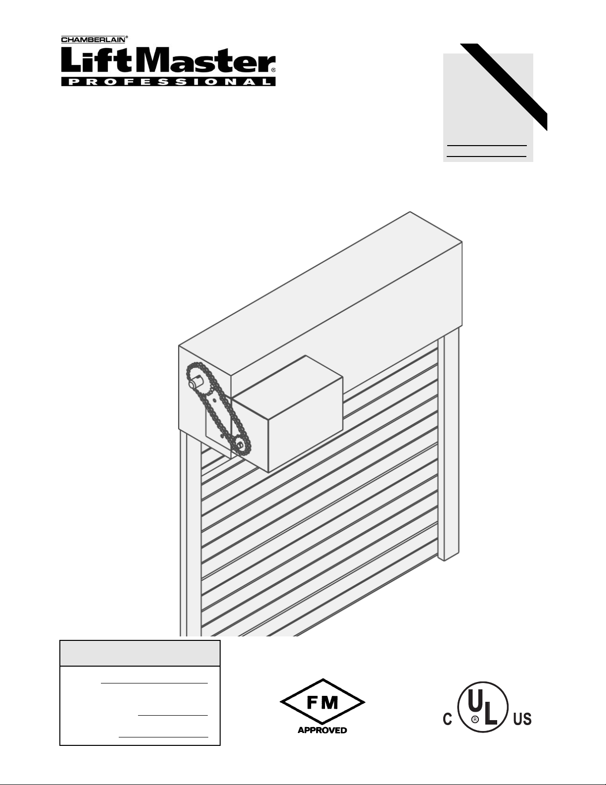
MODEL FDCL
ADVANCED LOGIC
INDUSTRIAL DUTY FIRE DOOR OPERATOR
NOT FOR RESIDENTIAL USE
LISTED DOOR OPERATOR
41B6
Serial #
(located on electrical box cover)
Installation Date
Wiring Type
2 YEAR WARRANTY
LMPLC CONTROL
LMPLC
CONTROL WIRED
Page 2
2
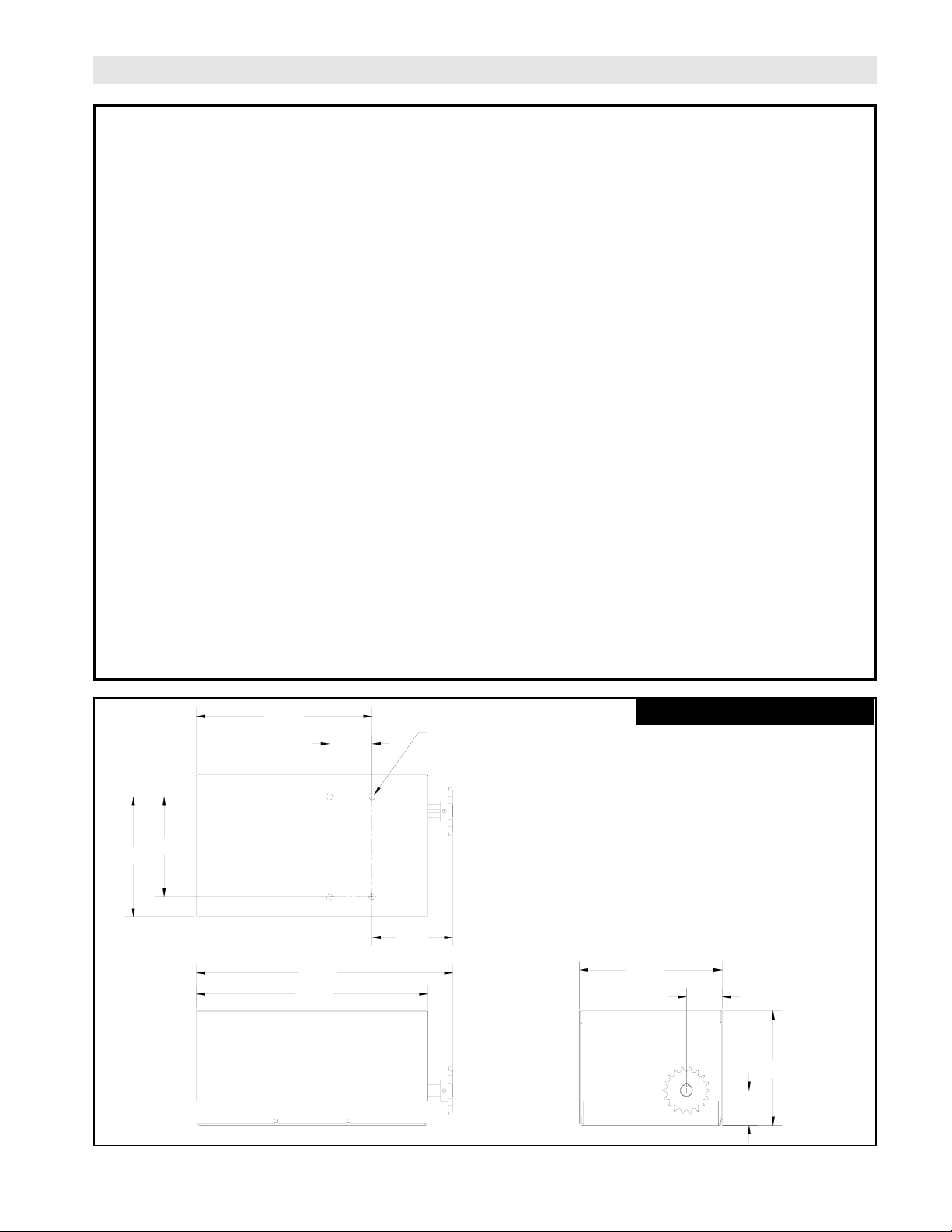
SPECIFICATIONS
19.11
9.43
2.86
11.78
2.96
21.16
14.50
3.50
9.92
8.25
3/8-16 SELF CLINCHING NUT
6.66
DRIVE SYSTEM
GEAR SYSTEM:..........................Mixed Spurgear/
Sprocket & Chain
CONTINUOUS POWER RATING:
1/2 HP: ................................140 ft-lbs/sec
OUTPUT SPEED
1/2 HP:......................................42.7 rpm
OUTPUT TORQUE
1/2 HP:......................................554 in-lbs.
OUTPUT SHAFT DIA.
1/2 HP: .....................................1”
OUTPUT SPROCKET
1/2 HP:......................................#50-18T
MAX. OVERHUNG LOAD:
1/2 HP:......................................375 Lbs.
MAX. BACK DRIVING FORCE: (torque)
1/2 HP: .....................................20 in-lbs.
MOTOR
TYPE: ....................................Continuous duty
HORSEPOWER: ...................1/2 HP
SPEED: .................................1750 RPM
VOLTAGE: ............................115/230 Single phase
230/460 Three Phase
ENCLOSURE:.......................ODP NEMA 48 Base Mount
ELECTRICAL
TRANSFORMER: ...............1PH: 120/240 VAC 24VAC
3PH: 240/480 VAC 24VAC
BATTERY BACKUP: (2) 12VDC .8AH Lead Acid
CONTROL STATION: ........NEMA 1 three button station.
OPEN/CLOSE/STOP
WIRING TYPE: ...................B2 for Fire Door Mode Type I
and revised C2 for Fire Door Mode Type
II.
LIMIT ADJUST:...................Linear driven, fully adjustable
screw type cams. (60 rev. max @ limit shaft)
DUTY CYCLE: ....................25 Reversing cycles per hour
BRAKE: ..............................24VDC Electromagnetic Disc
THERMAL SENSORS:.............160 deg. F (Open on rise manual
reset, see page 12)
ELECTRICAL ENCLOSURE RATINGS: motors, electrical enclosure and control station are rated NEMA1
WEIGHTS & DIMENSIONS
HANGING WEIGHT
1/2HP = 68 Lbs.
Page 3
3
GENERAL DESCRIPTION
THIS OPERATOR IS NOT A FIRE ALARM SYSTEM. IT
CAN NOT DETECT A FIRE CONDITION.
WARNING
The Fire Door Controller, FDCL, is an integrated fire door control system. It is designed to interface with normally close (NC) or normally open (NO) dry contact alarm system to control the operation of a fire door. Wiring for
sensing device to reverse and auxiliary devices to open and close are provided. The control station is selectable
between "Fire Door Mode Type I" and "Fire Door Mode Type II" by means of DIP SWITCH 2. When "Fire Door
Mode Type 1" is selected the control station is the standard B2 wiring, momentary contact to open, close and stop.
When "Fire Door Mode Type II" is selected the control station is a revised C2 wiring, momentary contact to open
& stop and constant pressure to close with no open override. In addition, when "Fire Door Mode Type II" is selected, the door will Gravity Close (governed descent) on alarm.
"Fire Door Mode Type I" is described throughout this manual. Refer to the above exceptions when in "Fire Door
Mode Type II" .
FUNCTIONAL OPERATION
1. Battery Management System
The batteries are charged, tested, and monitored automatically by the microprocessor based system.
The batteries are tested under load every thirty days. If for any reason the batteries fail this load test,
the on board buzzer will sound for 3 seconds of every minute to indicate that the batteries need to be
replaced. The load test will detect a catastrophic failure such as full loss of batteries when con
ducted with AC power present (customary situation).
When in Battery Backup mode (loss of AC power), the battery voltage is continuously monitored. Low
battery condition will be indicated by the on board buzzer sounding 3 seconds out of every minute, and
the low battery indicator (located on the key test station) flashing, until the batteries come to the full
charge or are replaced. The batteries must be present and at working voltage level (21V +) for this
function to work.
2. Unit has AC power & no alarm condition:
The 3-button control station is used to operate the door electrically.
Activation of the safety edge while the door is closing will cause the door to reverse to the full open limit.
Activation of the safety edge while the door is opening will NOT effect operation, the door will continue
to the open limit.
Activating the key-test switch for at least 6 seconds will put the operator in alarm active mode. (see
ACTIVE ALARM section for detail operation of alarm active mode)
3. Unit has AC power & active alarm condition (ALARM #1 - smoke alarm etc.):
The unit will activate the OPTIONAL warning signal, the door will automatically close after the preset
time delay (powered down by motor except in Fire Door Mode Type II). The time delay is set by means
of DIPswitch 1.
If the door is in the open position and an alarm condition occurs, the door will automatically close under
motor operation except in Fire Door Mode Type II. In the event the door should meet an obstruction while
closing, it will reverse and return to the full open position, and then start the closing cycle (with delay
and warning) again. If the obstruction is not removed, the door will close stopping at the lowest possible
position holding the brake for 2 seconds, then releasing the door to GRAVITY CLOSE (controlled
descent). If after the door has finished the cycling mode and obstruction has been removed, the door
will proceed to the floor.
In the event of a failure in motor operation, the operator will gravity close (controlled descent).
NOTICE
WARNING
Page 4

4
FUNCTIONAL OPERATION CONTINUED
4. Unit has AC power & active alarm condition (ALARM #2 - Fire Sensor, thermal sensor, fuse link.):
The unit will activate the optional warning signal (siren/strobe), the door will automatically close after the
preset time delay. (powered down by motor except in Fire Door Mode Type II) The time delay is set by
means of DIP switch 1.
If the door is in the open position and the alarm condition occurs, the door will automatically close under
motor operation (except in Fire Door Mode Type II). In the event the door should meet an obstruction while
closing, the door will stop for 2 seconds, then release the door to Gravity Close (controlled descent). After
the obstruction has been removed, the door will proceed to the floor.
In the event of a failure in motor operation, the operator will gravity close (controlled descent)
All control station functions will be rendered inactive in this condition.
The safety edge will remain active.
5. Unit has No AC power & No active alarm condition:
The Close and Stop buttons of the 3 button control station are functional.
The door's descending speed is controlled by the internal govenor.
The door will stop if an obstruction is encountered while closing.
Open button is not functional
6. Unit has No AC power & active alarm condition (Alarm #1 or Alarm #2):
The unit will activate the OPTIONAL warning signal (siren/strobe), the door will automatically close after
the preset time delay. (controlled by internal govenor) The time delay is set by means of DIP
switch 1.
If the door encounters an obstruction while closing , the door will stop on the obstruction, and release the
brake after (2) seconds. If the obstruction is then removed the unit will perform an controlled drop of the
door. (not powered down by the motor)
7. Activation of the internal Thermal Sensor:
Will activate an alarm #2 switch.
With AC power present the unit will react as stated in paragraph 4.
With No AC power present the unit will react as stated in paragraph 6.
8. Activation of the Key Test Station:
Key must be activated for 6 seconds
The unit will activate the OPTIONAL warning signal (siren/strobe), the door will automatically close after
the preset time delay. (controlled by internal govenor) The time delay is set by means of DIP switch 1. (to
test the signal devices and the delay time)
The door will close using gravity close mode (Controlled Descent) in order to test the door balance,
descent speed, and the moment of the door.
All sensing devices and control devices will be active. (In order to test these devices) (See page 5 for
procedures)
Page 5

Before beginning any testing, secure the door area, keep unauthorized personnel from entering the area during testing.
Be sure ac power is present at the operator, (the green "AC" LED will be lighted on the operators control board) and
that the batteries are connected and fully charged. (the red "DC" LED will NOT be lighted on the operators control
board)
1. Begin the test with your door at the full "OPEN" position.
2. If your door is equipped with safety photo eyes, make certain dip switch #4 is in the "ON" position.
Note: If 2 minutes total time elapses from the beginning of step #11and the conclusion of step #15, the unit will automatically exit the "TEST" mode. To re-enter the "TEST" mode repeat step #4, and continue testing.
3. Turn the wall mounted key test switch to the "TEST" position and hold for a minimum of 6 seconds. This action simulates an “ALARM” signal.
4. If dip switch #1 is in the "ON" position, the door should begin to close immediately. If dip switch #1 is in the "OFF"
position, the door should begin to close after 10 seconds time has elapsed. (the door will not motor down, it will gravity
descend)
5. Using a "stop-watch" verify that your door is closing between 6" and 24" per second. (i.e.. A 10ft high door should
close in a time between 5 and 20 seconds.) Your door should now be fully closed.
6. Open the door by depressing the "OPEN" button on the three button control station.
7. Repeat step #3.
8. When the door is approximately 3 to4 feet from the floor, activate the doors safety edge,(if so equipped) using
a crate, skid or alike. Do not introduce any part of your body to the door system during testing. The door should
reverse to the full open position. Remove the obstruction.
9. The door will begin to close within 1 sec., If dip switch #1 is in the "ON" position. If dip switch # 1 is in the "OFF" position, the door will wait 10 sec. Before beginning to close. The door should fully close to the floor. (the door will not motor
down, it will gravity descend)
10. Repeat steps #7 and #8.
11. When the door is approximately ½ way to the floor, interrupt the safety photo eye beam,(if so equipped) by
blocking with a piece of cardboard or alike. Do not introduce any part of your body to the door system during test
ing. The door should reverse to the full open position.Remove the obstruction.
12. Step #10 repeats.
13. When the door is approximately ½ way to the floor, depress and hold the "STOP" button on the three button control
station. The door should stop.
14. Release the "STOP" button on the control station. Step #10 repeats.
15. Depress the "OPEN" button on the three button control station. The door should open to the full open position. The
unit is now ready to be returned to service.
DOOR SYSTEM TESTING PROCEDURES
5
Page 6
6
Wall Mounting
The operator should generally be installed below the door
shaft, and as close to the door as possible. The optimum
distance between the door shaft and operator drive shaft
is between 12” - 15”. Refer to Figure 2.
OPERATOR MOUNTING
Bracket or Shelf Mounting
The operator may be mounted either above or below the
door shaft. The optimum distance between the door shaft
and operator drive shaft is between 12” - 15”. Refer to
Figure 1.
Before your operator is installed, be sure the door has been properly aligned and is working smoothly. The operator may
be wall mounted or mounted on a bracket or shelf. Refer to the illustration and instructions below that suits your application. This motor operator is an integral part of the door system. The motor operator, controls door descent speed under
power outage conditions, therefore the motor operator mounting surface is of major importance. The mounting must provide the following:
- All surfaces should be flat, square, and parallel to the door shaft
- The mounting surface must be rigid, and braced off as required
- When wall mounting the motor operator, it should be through bolted to the wall
- All (4) motor operator mounting points MUST be used
- All mounting hardware should be a minimum of grade 5
LOAD SPREADING PLATE
MOUNTED TO WALL BOTH SIDES
(SUPPLIED BY OTHERS)
HOOD MOUNT BRACKET
(SUPPLIED BY OTHERS)
NOTE: The door hood, end plates, and
mounting bracket must be rigid, and
provide adequate structural support.
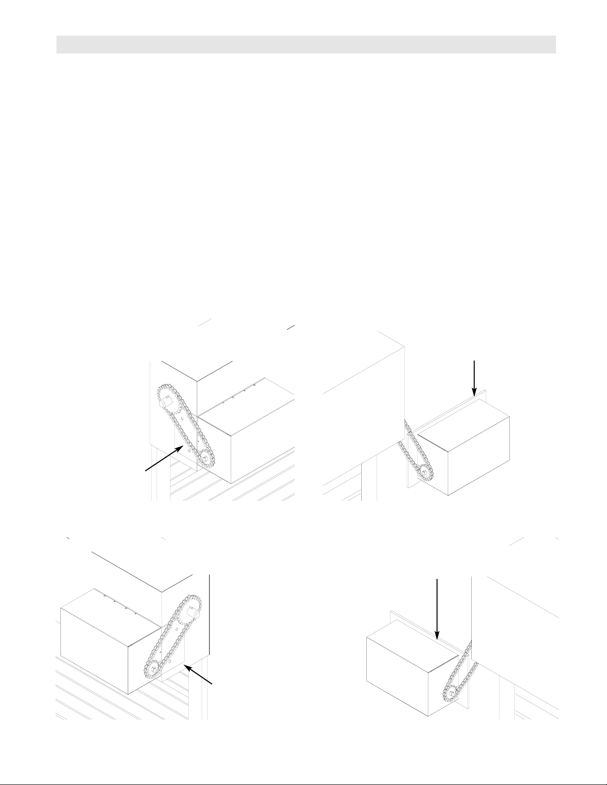
Liftmaster products are shipped for inside wall mount applications. If the operator is mounted to the front of the hood
the “Handing” is reversed. The last letter of the model number indicates the mounting with a “R” for right and “L” for left.
Left Hand Models (See Figures 1 & 2): FDCL5011L, FDCL5021L, FDCL5023L, FDCL5043L)
FIGURE 2
FIGURE 1
Right Hand Models (See Figures 3 & 4): FDCL5011R, FDCL5021R, FDCL5023R, FDCL5043R)
LOAD SPREADING PLATE
MOUNTED TO WALL BOTH SIDES
(SUPPLIED BY OTHERS)
HOOD MOUNT BRACKET
(SUPPLIED BY OTHERS)
FIGURE 4
FIGURE 3
NOTE: The door hood, end plates, and
mounting bracket must be rigid, and
provide adequate structural support.
Page 7
7
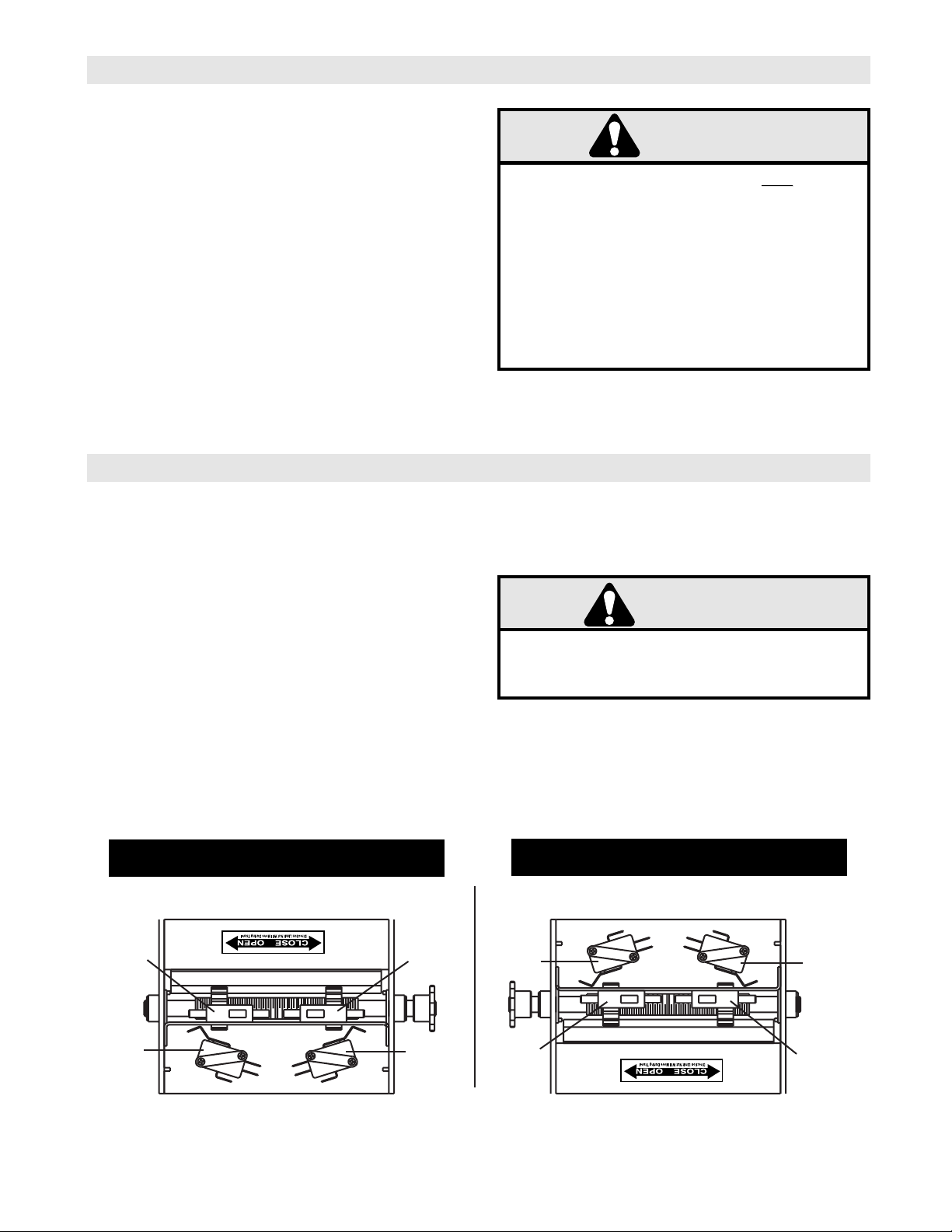
LIMIT SWITCH ADJUSTMENT
TO AVOID SERIOUS PERSONAL INJURY OR DEATH
FROM ELECTROCUTION, DISCONNECT ELECTRIC
POWER BEFORE MANUALLY MOVING LIMIT NUTS.
WARNING
MAKE SURE THE LIMIT NUTS ARE POSITIONED BETWEEN THE LIMIT SWITCH ACTUATORS BEFORE
PROCEEDING WITH ADJUSTMENTS.
If other problems persist, call our toll-free number for
assistance - 1-800-528-2806
1. To adjust limit nuts depress retaining plate to allow
nut to spin freely. After adjustment, release plate
and ensure it seats fully in slots of both nuts.
2. To increase door travel, spin nut away from actu-
ator. To decrease door travel, spin limit nut toward
actuator.
3. Adjust open limit nut so that door will stop in open
position with the bottom of the door even with top
of door opening.
4. Repeat Steps 1 and 2 for close cycle. Adjust close
limit nut so that actuator is engaged as door fully
seats at the floor.
LEFT HAND, FRONT OF HOOD /
RIGHT HAND, WALL MOUNT
RIGHT HAND, FRONT OF HOOD /
LEFT HAND, WALL MOUNT
OPERATOR MOUNTING CONTINUED
1c. Place door sprocket on the door shaft. Do not
insert the key at this time.
2. Wrap drive chain around door sprocket and join
roller chain ends together with master link. (Link
clip should face away from operator.)
3. Raise operator to approximate mounting position
and position chain over operator sprocket.
4. Raise or lower operator until the chain is taut (not
tight). Make sure the operator output shaft is parallel to door shaft and sprockets are aligned. When
in position, secure the operator to wall or mounting
bracket.
5. Install all remaining drive keys and set screws.
Apply “Loctite-262” or equivalent locking
compound to set screws. (Check that all mounting
hardware is tight, and the drive chains are taut.
THIS FIREDOOR CONTROLLER WILL
NOT
NOT
CLOSE A
BALANCED DOOR IN THE ABSENCE OF AC
POWER.THE DOOR SYSTEM MUST BE ABLE TO
GENERATE A MINIMUM BACKDRIVING TORQUE OF
100 IN/LBS.,AT THE OPERATOR OUTPUT SHAFT.
STICKING OR BINDING DOORS MUST BE
REPAIRED. DOORS, DOOR SPRINGS, BRACKETS
AND THEIR HARDWARE MAY BE UNDER EXTREME
TENSION AND CAN CAUSE SERIOUS PERSONAL
INJURY. CALL A PROFESSIONAL DOOR SERVICEMAN TO MOVE OR ADJUST DOOR SPRINGS OR
HARDWARE.
WARNING
WARNING
SPARE
AUXILIARY
LIMIT
AUXILIARY
CLOSE LIMIT
WARNING
OPEN
LIMIT
CLOSE
LIMIT
OPEN
LIMIT
CLOSE
LIMIT
SPARE
AUXILIARY
LIMIT
AUXILIARY
CLOSE LIMIT
Page 8

8
Alarm Inputs:
Alarm Input #1:
Used for electronic alarm devices such as smoke detection devices or similar
alarm systems. Devices may be N/O or N/C. Switchable using DIP Switch #3. This alarm will
activate a motored closure of the door (except in Fire Door Mode Type II), and all sensing and
control devices will remain active.
It is imperative that the alarm signal contact is maintained for a time period greater than the alarm
delay to close setting. I.E. If dip switch #1 is in the “OFF” position (10 seconds) the alarm system
must supply a “DRY” contact signal to terminals J2-11 & J2-12 for a minimum of 12 seconds.
Alarm Input #2:
Used for the thermal sensors (electronic fusible links), fuse link kit or similar
systems. (N.C. state only) This alarm condition will activate a motored closure of the door (except
in Fire Door Mode Type II), and all sensing devices and control stations will be rendered inactive.
EXCEPT THE SAFETY EDGE. This alarm will override any other alarm condition or input.
NOTICE:
This equipment has been tested and found to comply with the limits for a Class A digital device, pursuant
to Part 15 of the FCC Rules. These limits are designed to provide reasonable protection against harmful
interference when the equipment is operated in a commercial environment. This equipment generates,
uses, and can radiate radio frequency energy and, if not installed and used in accordance with the instruction manual, may cause harmful interference to radio communications. Operation of this equipment in a
residential area is likely to cause harmful interference, in which case the user will be required to correct the
interference at his own expense.
INSTALLATION MODE
PHOTO EYES
NOTE: LiftMaster recommends the use of safety
photo eyes as a non-contact method of entrapment
protection.
The operator has been manufactured to accept direct
connection of LiftMaster Infrared Eyes. See page 11
for proper dip switch settings, and pages 14 & 15 for
wiring connections. Follow the wiring instructions supplied with your LiftMaster Infrared Eyes.
ENTRAPMENT PROTECTION ACCESSORIES
ELECTRIC OR PNEUMATIC EDGE
This operator will also accept various safety edges
offered by LiftMaster. See pages 14 and 15 for proper wiring connections to the operator.
Page 9

9
INSTALL POWER WIRING & CONTROL STATION
Before installing power wiring or control stations be sure to follow all specifications and warnings described below. Failure to do so may result in severe injury to persons and/or damage
to operator.
Do not install any wiring or attempt to run the operator without consulting the wiring diagram.
Install the optional Reversing Edge before proceeding with the Control Station installation.
DISCONNECT POWER AT THE FUSE BOX BEFORE
PROCEEDING.
OPERATOR MUST BE PROPERLY GROUNDED AND
PERMANENTLY WIRED IN ACCORDANCE WITH
LOCAL ELECTRICAL CODES. NOTE: THE OPERATOR SHOULD BE ON A SEPARATE FUSED LINE OF
ADEQUATE CAPACITY.
ALL ELECTRICAL CONNECTIONS MUST BE MADE
BY A QUALIFIED INDIVIDUAL.
WARNING
TO ENSURE DOOR DESCENT IN AN “ALARM” CONDITION, AND AVOID DAMAGE TO DOOR AND OPERATOR, MAKE ALL DOOR LOCKS INOPERATIVE.
SECURE LOCK(S) IN "OPEN" POSITION.
IMPORTANT SAFETY NOTES
ANY MAINTENANCE TO THE OPERATOR OR IN THE
AREA NEAR THE OPERATOR MUST NOT BE PERFORMED UNTIL DISCONNECTING THE ELECTRICAL POWER AND LOCKING-OUT THE POWER VIA,
THE MAIN DISCONNECT SWITCH. UPON COMPLETION OF MAINTENANCE THE AREA MUST BE
CLEARED AND SECURED, AT THAT TIME THE UNIT
MAY BE RETURNED TO SERVICE.
WARNING
INSTALL THE CONTROL STATION WHERE THE DOOR
IS VISIBLE, BUT AWAY FROM THE DOOR AND ITS
HARDWARE. DO NOT INSTALL CONTROL STATION
DIRECTLY BENEATH THE OPERATOR. IF CONTROL
STATION CANNOT BE INSTALLED WHERE DOOR IS
VISIBLE, OR IF ANY DEVICE OTHER THAN THE CONTROL STATION IS USED TO ACTIVATE THE DOOR, A
SAFETY DEVICE MUST BE INSTALLED ON THE
DOOR, THE MINIMUM ACCEPTABLE DEVICE
WOULD BE SAFETY PHOTO EYES, OR A REVERSING EDGE INSTALLED ON THE BOTTOM OF THE
DOOR. THE BEST PROTECTION IS AFFORDED BY
THE COMBINATION OF THESE TWO DEVICES.
WARNING
THIS UNIT MUST BE PROPERLY GROUNDED.
A GROUND SCREW IS SUPPLIED IN THE
ELECTRICAL BOX FOR CONNECTION OF THE
POWER SUPPLY GROUND WIRE. FAILURE TO
PROPERLY GROUND THIS UNIT COULD
RESULT IN ELECTRIC SHOCK AND SERIOUS
INJURY.
IMPORTANT
WARNING
WARNING
WARNING
WARNING
WARNING
Page 10

10
CONTROL STATION MOUNTING
POWER WIRING CONNECTIONS
1. Connect power wires to the J1 terminal block located on the Printed Circuit Board (shown below).
2. Be sure to run all power wires through the conduit
hole in the electrical box enclosure marked with the label
shown below.
POWER WIRING
CONTROL STATION WIRING
CONTROL WIRING CONNECTIONS
1. Connect control wires to the J2 terminal block located on the Printed Circuit Board (shown below).
2. Be sure to run all control wires through the conduit
hole in the electrical box enclosure marked with the label
shown below.
3. Apply power to the operator. Press OPEN push button and observe direction of door travel and then Press
the STOP button.
If door did not move in the correct direction, check for
improper wiring at the control station or between operator and control station.(See page 19)
GROUND WIRING
1. Connect earth ground to chassis ground screw in the
electrical box enclosure marked with the label shown
below.
2. Use same conduit entry into the electrical box as the
power wiring.
4 ft.
(Approximate)
1. Mount Control Station and Key Test Switch no further
than 12” from each other.
2. Mount Control Station and Key Test Switch within
clear line of sight of door.
3. Mount WARNING NOTICE beside or below the
Control Station, and key test station as shown to the left.
Control
Station
Key
Test
Station
(Right Hand Unit Shown)
“UL” WARNING
(SEE NOTE)
NOTE:
The “UL” Warning label must be read “right side up” from the
floor level. Should your operator mounting cause this label to
be read “upside down”, your accessory kit is supplied with an
additional label. Install the new label so that it will be read
“right side up “ from the floor level.
P/N: 40-6000
P/N: 40-17244
40-10033B
LOW BATTERY INDICATOR FLASHING
IS AN INDICATION THAT OPERATOR BATTERIES REQUIRE SERVICING.
REFER TO OWNERS MANUAL FOR PROPER SERVICE PROCEDURE.
NORMAL OPERATION MODE IS AFFECTED DURING THIS CONDITION
THERE MAY BE NO "CLOSE" DELAY PERIOD AVAILABLE IN THE
EVENT OF A FIRE ALARM CONDITION.
MOMENTARY "OPEN" CONTROL IS DEFEATED AT THE "3-BUTTON"
STATION.
TO OPEN THE DOOR, CONSTANT PRESSURE MUST BE MAINTAINED ON
THE "OPEN" BUTTON, FOR A MINIMUM OF 5 SECONDS, AND THE ENTIRE
RANGE OF DESIRED OPENING.
40-17244A
Page 11

11
OFF
NOTICE:
This equipment has been tested and found to
comply with the limits for a Class A digital
device, pursuant to Part 15 of the FCC Rules.
These limits are designed to provide reasonable protection against harmful interference
when the equipment is operated in a commercial environment. This equipment generates,
uses, and can radiate radio frequency energy
and, if not installed and used in accordance
with the instruction manual, may cause harmful
interference to radio communications.
Operation of this equipment in a residential
area is likely to cause harmful interference, in
which case the user will be required to correct
the interference at his own expense.
OPTIONAL CONTROL SETTINGS
NOTE: All functions are independent of each other and do not require other control settings to be set at any cer-
tain configuration. For dip switch location refer to illustration on next page. All switches are factory preset to the
“OFF” position.
S1-1 ALARM DELAY TO CLOSE - Alarm Delay to Close is the time between when the operator first receives an
active alarm signal and the door starts to close. (In Seconds)
S1-4 INFRARED EYES STATE - The operator will support LiftMaster Infrared Safety Photo Eyes when enabled,
and ignore IR inputs when disabled.
TERMINAL
BLOCK (J2)
TERMINAL
BLOCK (J1)
HEAT SINK
DIP SWITCH (S1)
INSTALLER CONTROL SETTINGS
S1-2 MODE - The factory default for the operator is standard Fire Door Mode Type I (OFF). Setting S1-2 to the
(ON) position selects the Fire Door Mode Type II. When Fire Door Mode Type I is selected, the control
station is in the standard B2 wiring, momentary contact to open, close and stop. When Fire Door Mode
Type II is selected, the control station is in revised C2 wiring, momentary contact to open & stop, constant
pressure to close with no open override. In addition, when Fire Door Mode Type II is selected, the door
will Gravity Close (governed descent) on alarm.
S1-3 ALARM STATE - The operator can accept either a normally open or normally closed dry contact alarm
input. DO NOT INDUCE VOLTAGE!
ON (0 SECOND DELAY)
1 2 3 4
OFF (10 SECOND DELAY)
ON (IR'S ENABLED)
1 2 3 4
(IR'S DISABLED)
ON (FIRE DOOR MODE TYPE II)
1 2 3 4
OFF (FIRE DOOR MODE TYPE I)
ON (N.C. ALARM)
1 2 3 4
OFF (N.O. ALARM)
Page 12

12
ELECTRONIC FUSE LINK ARRANGEMENT
A permanent fuse link arrangement shall be set-up for all
installations. Use the illustration to the right as a guide.
1. Mount (2) single gang junction boxes (not supplied) on the
center line of the door (one on each side of the door opening),
see example below. Install (2) thermal sensors (supplied with
cover plates and screws) to the junction boxes installed in step
#1.
NOTE: Reference NFPA80, or applicable state and local codes
for proper installation
2. Wire sensors in series making required connections to
motor operator. (TB1-5, TB1-6) Remove and discard factory
supplied “jumper” and wire as shown on pages 16 and 17.
(Alarm input #2)
3. All wiring and conduit should be run in accordance with all
state and local electrical codes.
SINGLE GANG
JUNCTION BOX
(*2 REQ’D NOT
SUPPLIED)
RUN CONDUIT
THROUGH WALL
JUNCTION
BOX
CENTER LINE
OF DOOR
THERMAL
SENSOR
(*2 SUPPLIED)
4 IN.
(0.1 M)
4 IN.
(0.1 M)
MINIMUM
12 IN.
(0.3 M)
MAXIMUM
SIDEWALL
CEILING
NOTE:
MEASUREMENTS SHOWN ARE TO THE
CLOSEST EDGE OF THE DETECTOR.
ACCEPTABLE HERE
EXAMPLE OF PROPER MOUNTING FOR DETECTORS
NEVER HERE
TOP OF DETECTOR
ACCEPTABLE HERE
DOOR HOOD
Page 13

13
KEY-TEST
IMPORTANT NOTES:
The 3-Button Control Station provided must be connected for operation.
Keyswitch
9 10 11 12
Stop
Close
Open
6 7 8
SENSING DEVICE TO REVERSE OR STOP
3 BUTTON STATION AND SYSTEM TEST ALARM SYSTEM NO OR NC CONTACTS
5
6
Sensing Device
11
12
NC Contacts
11
12
NO Contacts
J2
J2
J2
J2
Must set DIP switch #3
(S1,3) to ON.
Must set DIP switch #3
(S1,3) to OFF.
15
24
Low Battery
Indicator
CONTROL CONNECTION DIAGRAM
OPTIONAL MECHANICAL (RETROFIT) FUSE LINK ARRANGEMENT #71-17148
EXISTING FUSE LINK
EXISTING FUSE LINK CHAIN
FUSE LINK RETROFIT
SWITCH (OPTIONAL)
CENTER LINE
OF DOOR
1. Mount (optional) fuse link retrofit switch in any convenient location to interface with existing fuse link
arrangement.
2. Connect existing fuse link chain to "key-ring" on
fuse link switch.
3. Adjust existing fuse link arrangement to be sure
that proper tension is supplied to the fuse link switch
actuator (key-ring). The actuator should be fully
extended. There should be continuity between the
switch leads. (Normally Closed).
4. Release the fuse link and be sure the fuse link
switch actuator (key-ring) retracts completely with no
binding. There should be NO continuity between the
switch leads. (Open Electrically).
5. Wire fuse link switch leads through conduit (not
supplied).
a) Remove factory supplied "Jumper"
between TB1-5, TB1-6 and discard.
b) Make required connections to motor
operator TB1-5, TB1-6 (Alarm Input #2).
NOTE: For additional wiring help refer to wiring diagrams on pages 16 & 17.
6. All wiring and conduit should be run in accordance
with all state and local electrical codes.
Page 14

14
STANDARD POWER & CONTROL CONNECTION DIAGRAMS
LMPLC Board - 115/230V 1PH
(RD)(WH)
LOW BATTERY
INDICATOR
13 141516 17 18 19 20 21 22 23
(BR)
(FACTORY JUMPER)
123456789101112
J2
24
J1
L1 L2 L3
TB1
IR'S
INTERNAL
THERMAL
SENSOR
1 2 3 4 5 6 7 8 9 10
24 VAC
GRD
+24 VDC
(1 AMP MAX)
(1 AMP MAX)
ALARM INPUT#2
(FACTORY JUMPER SUPPLIED)
ELECTRONIC
FUSE LINK
C
KEY-TEST
OPEN
CLOSE
STOP
REVERSE
EDGE
NO
115/230V
HOT
ALARM INPUT #1
(DRY CONTACT)
N.O. or N.C.
115/230V
NEUTRAL
POWER IN 115/230V 1PH
GND
Page 15

15
STANDARD POWER & CONTROL CONNECTION DIAGRAMS
LMPLC Board - 230/460V 3PH
(RD)(WH)
LOW BATTERY
INDICATOR
13 141516 17 18 19 20 21 22 23
(BR)
(FACTORY JUMPER)
123456789101112
J2
24
J1
L1 L2 L3
TB1
IR'S
INTERNAL
THERMAL
SENSOR
1 2 3 4 5 6 7 8 9 10
24 VAC
GRD
+24 VDC
ELECTRONIC
FUSE LINK
(1 AMP MAX)
(1 AMP MAX)
ALARM INPUT#2
(FACTORY JUMPER SUPPLIED)
C
KEY-TEST
OPEN
CLOSE
STOP
REVERSE
EDGE
NO
ALARM INPUT #1
(DRY CONTACT)
N.O. or N.C.
L1 L2 L3 GND
POWER IN 230/460V 3PH
Page 16

16
(SHOWN AS RIGHT HAND UNIT)
1 PHASE WIRING DIAGRAM (FDCL5011 & FDCL5021)
1920-1
1. See owners manual for DIP Switch Functions and Programming Procedures.
2. Connections Shown in Dotted Boundaries are Optional User Interface.
**
(K7, K8) ARE NORMALLY OPEN DRY CONTACTS WHICH ARE PROGRAMMED
TO CLOSE ON ANY ALARM SIGNAL.
**
(K6) IS NORMALLY OPEN DRY CONTACT WHICH IS PROGRAMMED TO CLOSE
WHEN THE DOOR IS IN MOTION OR INHIBITED DURING A GRAVITY CLOSE.
3. To reverse motor direction reverse GREY and PURPLE wires at J6 and J7 on the
LMPLC board.
GENERAL NOTES
SPARE
LIMIT SWITCH
12 VDC
BATTERY
X2
(K6) OPTIONAL
MOTION STROBE
(K7) OPTIONAL
FIRE SIREN
(K8) OPTIONAL
FIRE STROBE
(1 AMP MAX)
ALARM INPUT #2
(FACTORY JUMPER
SUPPLIED)
ELECTRONIC
FUSELINK
24 VAC
(1 AMP MAX)
24 VAC
+24 VDC
(1 AMP MAX)
GRD
OUTPUTS
TB1
BATTERY
DISCONNECT
(BK)
-
+
-
(RD)
+
**
+12VDC
GND
10
9
8
7
6
5
4
3
2
1
INTERNAL
THERMAL
SENSOR
(BK)
(BR)
(BR)
(RD)
(BK)
(YE)
(RD)
(BL)
(BK)
J14
J15
(RD)
J13
J12
J9
J8
(BK)
(BK)
SAFETY
LIMIT SWITCH
CLOSE
LIMIT SWITCH
(WH)
OPEN
LIMIT SWITCH
J3
J4
S1
181716151413 242322212019
FACTORY JUMPER (BR)
123456 7 8 9 10 11 12
J2
KEY-TEST
COM NO
OPEN
IR'S
REVERSING
EDGE
(WH)
CLOSE
STOP
RESISTOR
CAPACITOR
DC
BRAKE
(BK)
J30 J18 J17 J16
COIL
(WH)
(BL)
(RD)
+-
+-
(WH)
(RD)
J19 J5
(YE)
J22
J26
J27
(BK)
(BK)
OVERLOAD
(DRY CONTACT ONLY, DO NOT
J1
L2L1
115 V 1 PHASE
POWER IN ONLY
ALARM INPUT #1
INDUCE VOLTAGE)
(BK)
(YE)
(BK)
L3
INTERNAL 230V - 1PH
MOTOR CONNECTION
5
(BK)
(YE)
4
(BL)
1
(OR)
3
(WH)
2
(RD)
8
INTERNAL 115V - 1PH
MOTOR CONNECTION
(RD) 8
SEE NOTE 3
J21
J24
J23
(PU)
J6
(GY)
J7
J25
(BL)
J28
J20
J29
GND
(BK) 5
(YE) 4
(WH) 2
(OR) 3
(BL) 1
(BL)(NOT USED)
(YE)
(GY)
(PU)
(BR)
(BR)
SECONDARY
PRIMARY
(WH)
(BK)
LOW BATTERY
INDICATOR
Page 17

17
3 PHASE SCHEMATIC (FDCL5023 & FDCL5043)
1920-3
(SHOWN AS RIGHT HAND UNIT)
1. See owners manual for DIP Switch Functions and Programming Procedures.
2. Connections Shown in Dotted Boundaries are Optional User Interface.
**
(K7, K8) ARE NORMALLY OPEN DRY CONTACTS WHICH ARE PROGRAMMED
TO CLOSE ON ANY ALARM SIGNAL.
**
(K6) IS NORMALLY OPEN DRY CONTACT WHICH IS PROGRAMMED TO CLOSE
WHEN THE DOOR IS IN MOTION OR INHIBITED DURING A GRAVITY CLOSE.
3. To reverse motor direction reverse GREY and PURPLE wires at J6 and J7 on the
LMPLC board.
GENERAL NOTES
SPARE
LIMIT SWITCH
12 VDC
BATTERY
X2
OUTPUTS
(K6) OPTIONAL
MOTION STROBE
(K7) OPTIONAL
(K8) OPTIONAL
FIRE STROBE
(1 AMP MAX)
ALARM INPUT #2
(FACTORY JUMPER
SUPPLIED)
ELECTRONIC
FUSELINK
(1 AMP MAX)
(1 AMP MAX)
**
FIRE SIREN
+12VDC
24 VAC
24 VAC
+24 VDC
GRD
GND
BATTERY
DISCONNECT
-
+
-
+
TB1
10
9
8
7
6
5
4
3
2
1
(BK)
(RD)
INTERNAL
THERMAL
SENSOR
(BK)
(BR)
(BR)
(RD)
(BK)
(YE)
(RD)
(BL)
J14
J15
J13
J12
J9
J8
(BK)
(BK)
(BR)
SECONDARY
SAFETY
LIMIT SWITCH
CLOSE
LIMIT SWITCH
(WH)
OPEN
LIMIT SWITCH
J3
13
14
1234
J2
IR'S
REVERSING
EDGE
(WH)
(WH)
(BK)
PRIMARY
J4
S1
18
1615
17
FACTORY JUMPER (BR)
5678910
KEY-TEST
COM NO
CLOSE
LOW BATTERY
INDICATOR
2019
OPEN
STOP
(BK)
J30
J18 J17 J16
2221
(RD)
RESISTOR
CAPACITOR
DC BRAKE
(WH)
(BL)
23
24
11 12
COIL
(BR)
(BR)
INTERNAL 460V - 3 PH
MOTOR CONNECTION
7
5
8
9
6
INTERNAL 230V - 3 PH
MOTOR CONNECTION
+-
(RD)
+-
(WH)
J5
J19
(YE)
J22
J26
J27
(BK)
230 / 460 V 3PH
POWER IN
ALARM INPUT #1
(DRY CONTACT ONLY, DO NOT
INDUCE VOLTAGE)
(YE)
SEE NOTE 3
J21
J24
J23
(PU)
J6
(GY)
J7
(BK)
J25
(BK)
J28
J20
J1
L2L1
J29
L3
GND
(BR)
14
(GY)
2
(PU)
3
(YE)
(BR)
5
6
4
897
3
2
1
Page 18

18
MAINTENANCE SCHEDULE
*
Use SAE 30 Oil (Never use grease or silicone spray).
Repeat ALL procedures.
Do not lubricate motor. Motor bearings are lubricated and sealed at the factory.
Inspect and service whenever a malfunction is observed or suspected.
CAUTION: BEFORE SERVICING, ALWAYS DISCONNECT OPERATOR FROM POWER SUPPLY.
Check at the intervals listed in the following chart.
EVERY EVERY EVERY
ITEM PROCEDURE 3 MONTHS 6 MONTHS 12 MONTHS
Drive Chain Check for excessive slack.
Check & adjust as required.
Lubricate.*
Governer, Brake
Check set screw tightness
Sprockets & Spur Gears
Fasteners Check & tighten as required
Bearings & Shafts Check for wear & lubricate
Functionality Activate Key Test switch (see pg. 4) Monthly or as required by regulatory agency
Gearbox: The gearbox on the motor operator is factory sealed, and non vented, and should not require service for thelife of the operator.
Brake Friction Material: The electromagnetic brake on the motor operator is factory adjusted, and should not require
service for the life of the operator. Should service be required, the entire unit should be replaced.
Operators require practically no special maintenance other than periodic checking to see that mechanical parts
where necessary are lubricated and the electrical compartments are clear of dirt.
Service technicians should familiarize themselves with the proper sequence of operation and all related controls.
Power to operator must be disconnected when removing or replacing covers on electrical components, making
adjustments, or performing maintenance.
1. Check wire connections for tightness and wire insulation for defects of abrasions.
2. Check to see that all conduit connections are secure.
3. Check wires to safety edge, or infrared safety eyes, if unit is equipped with a safety to reverse feature.
4. Inspect operation of brake.
5. Inspect for debris.
6. Inspect roller chain and drive sprockets. Align, lubricate the sprockets, and tighten the set screws.
7. Generally inspect the motor mounting, and tighten the fasteners and bracing.
8. Verify that all conduit connections are tight and have no exposed wires.
9. Inspect the electrical enclosure for debris, arching and moisture. Check for and tighten loose wiring connections.
10. Test motor operation through all control stations.
11. Check limit switch settings.
12. Examine safety edge, coil cord and take-up reel for damage.
13. Test the operation of the safety edge.
14. Check motor amperage draw for a full open and close cycle. Compare readings to those listed on the motor
nameplate.
MOTOR OPERATOR MAINTENANCE
Page 19

19
MOTOR OPERATOR TROUBLE SHOOTING GUIDE
Motor does not run when OPEN or
CLOSE button is pushed.
Motor runs but door does not
move.
Motor hums but does not run.
Operator runs in wrong direction
and limits do not function.
Limit switches do not hold their
settings.
Door ‘drifts’ when motor shuts off.
Operator does not shut off at full
OPEN or at full CLOSE position.
Operator Functions Erratically
Check circuit breaker, power fuses, safety
switch; check cause.
Reset; check cause.
Check fuse, check cause.
Close interlocks.
Check drive train for operation
Close & lock off door, remove motor and
inspect; check cause.
Check door. Try to operate manually.
Check power supply.
Check power to brake coil.
Check all motor connections.
Interchange any 2 wires in 3O
Adjust chain to proper tension.
Be sure retainer is in slots of BOTH nuts.
Lubricate screw thread. Limit nuts should
turn freely.
Check brake operation.
Adjust (see above)
Inspect limit chain & sprocket. Adjust chain
tension, replace sprocket & chain if
required
Operate limit switch manually to determine.
Check line voltage at operator. Low voltage,
check cause.
Check circuit for high current draws.
Eliminate all other units from the circuit.
Check ground connections. Check alarm
circuits.
Simultaneously depress the “OPEN” &
“CLOSE” limit switches, this will reset the
operator’s microprocessor.
Circuit breaker tripped or power fuse
blown.
Thermal overload tripped.
Secondary transformer fuse blown.
External interlock open. (if supplied)
Sprocket key missing or drive chain broken.
Intermediate shaft or key damaged.
Door jammed. Drive train jammed.
Dead phase in 3 phase system.
Brake does not release.
Open motor winding.
On 3 phase operators power supply is out
of phase.
Drive chain loose, allows chain to jump
sprocket teeth.
Limit nut retainer not engaging slots in limit
nuts.
Limit nuts binding on screw threads which
allows them to jump position on retainer.
Brake inoperative or worn.
Limit nuts not adjusted properly.
Sprocket on limit shaft loose or limit drive
chain broken.
Defective limit switch
Low line voltage
Bad ground
“Noise” on electrical line
Faulty alarm wiring
Note: All units are checked for proper rotation at factory. Limit switch adjustment
instructions in electrical enclosure indicates proper direction of travel for OPEN and
CLOSE limit nuts. Note: See discussion on page 11 for S1-2.
SYMPTOM
POSSIBLE CAUSE
REPAIR
Page 20

20
REPAIR PARTS KITS – ELECTRICAL BOX
Refer to the parts lists below for replacement kits available for your operator. If optional modifications and/or
accessories are included with your operator, certain components may be added or removed from these lists.
Individual components of each kit may not be available. Please consult a parts and service representative regarding availability of individual components. Refer to page 24 for all repair part ordering information.
MOTOR ASSEMBLY KIT
ITEM PART # DESCRIPTION QTY
M1
M2
M3
M4
COUPLING, L-JAW
COUPLING, SPIDER
MOTOR, 1/2HP 115/230V (1 PHASE UNITS)
MOTOR, 1/2HP 230/460V (3 PHASE UNITS)
FLANGE NUT, 1/4"
2
1
1
4
07-17247
07-17483
20-1050B-2F
20-3050B-4F
84-FN-25
ELECTRICAL ASSEMBLY
ITEM PART # DESCRIPTION QTY
1
2
3
4
5
6
7
8
9
10
11
12
13
14
15
16
17
18
19
20
BRACKET, BATTERY
BRACKET, COMPONENT
BRACKET, MOUNTING PCB
XFMR (115/23OV 1PH UNITS)
XFMR (230/46OV 1PH UNITS)
OVERLOAD (115V 1PH UNITS)
OVERLOAD (230V 1PH UNITS)
VENT PLUG, 29/64 LONG
DOME PLUG, 13/32 LONG
HOLE PLUG
THERMAL SENSOR
BATTERY
STANDOFF
TERMINAL BLOCK
HEX BOLT, 1/4-20
SCREW, #6-32 SELF TAPPING
SCREW, #8-32
SCREW, #8-32
FLANGE NUT, #8
LOCK WASHER
KIT, POWER RESISTOR
KIT, FDCL BOARD
1
1
1
1
1
1
1
2
1
2
1
2
4
1
4
2
4
2
4
4
1
1
10-17214
10-17627
10-17636
21-16699
21-16698
25-2010
25-2006
28-17222
28-17223
28-4875
29-16241
29-NP08-12
31-17635
42-110
82-HN25-08
82-PX06-05T
82-PX08-04T
82-PX08-10T
84-FN-08
85-LS-25
K74-16514
K79-13493-2
K20-1050B-2F Models FDCL5011, FDCL 5021
K20-3050B-4F Models FDCL5023, FDCL5043
K75-17351 COVER ASSEMBLY KIT
ITEM PART # DESCRIPTION QTY
C1
C2
C3
C4
COVER, FDCL
PLATE, IDENTIFICATION FDCL
LABEL, UL CAUTION
SCREW, #6-32
1
1
1
4
10-17067
10-17234
40-16485
82-PX06-06
ACCESSORIES
02-109FDC KEY TEST STATION 1
02-103 3 BUTTON STATION 1
74-16685 THERMAL SENSOR 2
71-17148 FUSE LINK KIT 1
K77-XXXXX LABEL KIT
PART # DESCRIPTION QTY
LABEL, GROUND
LABEL, 115V 1 PHASE (115V 1PH ONLY)
LABEL, 230V 1 PHASE (230V 1PH ONLY)
LABEL, 230V 3 PHASE (230V 3PH ONLY)
LABEL, 460V 3 PHASE (460V 3PH ONLY)
LABEL, DIRECTION
LABEL, (1-10)
LABEL, WIRING DIAGRAM (1PH ONLY)
LABEL, WIRING DIAGRAM (3PH ONLY)
LABEL, FDC EBOX UL CAUTION
LABEL, CLASS 2 CIRCUIT
LABEL, DOOR OPERATOR WARN. SIGN
LABEL, DOOR EDGE CAUTION
LABEL, RESET
LABEL, RATING
LABEL, (L1, L2, L3) WARNING
LABEL, KEYSTATION WARNING
1
1
1
1
1
1
1
1
1
1
1
1
2
1
1
1
1
132A2060
40-10231
40-10232
40-10233
40-10234
40-10306
40-10222
40-17480
40-17481
40-16485
40-16509
40-6000
40-65
40-790
40-9054
40-16709
40-17244
Page 21

21
ILLUSTRATED PARTS – CHASSIS ASSEMBLY
SEE PAGES 22 & 23
C4
M2
M1
13
20
8
10
15
1
M4
6
7
12
16
4
15
14
17
2
9
5
M3
C3
C2
C1
19
18
3
Page 22

22
REPAIR PARTS KITS – MODEL FDCL
Refer to the parts lists below for replacement kits available for your operator. If optional modifications and/or
accessories are included with your operator, certain components may be added or removed from these lists.
Individual components of each kit may not be available. Please consult a parts and service representative regarding availability of individual components. Refer to page 24 for all repair part ordering information.
K72-17352 LIMIT SHAFT ASSEMBLY KIT
ITEM PART # DESCRIPTION QTY
S1
S2
S3
S4
S5
S6
S7
SHAFT, LIMT
BEARING FLANGE
LIMIT NUT
SPROCKET, 25B12
SPACER
ROLL PIN, 1/8"
E-RING
1
2
2
1
2
1
2
11-17209
12-10028
13-10024
15-25B12AXX
80-10022
86-RP04-100
87-E-038
GEAR HOUSING ASSEMBLY
ITEM PART # DESCRIPTION QTY
BRAKE SHAFT ASSEMBLY
1
2
3
4
5
6
7
8
9
10
11
SIDE PLATE, MAIN
SIDE PLATE, OUTPUT
SIDE PLATE, SPUR GEAR
CHAIN, #25 X 47 LINKS
CHAIN, #35 X 47 LINKS
STANDOFF, 5.312 LONG
STANDOFF, 3.625 LONG
STANDOFF, 1.562 LONG
HEX BOLT 1/4 X 1/2"
FLANGE NUT, 1/4
LOCKWASHER, 1/4
1
1
1
1
1
2
4
2
6
15
6
10-17062
10-17063
10-17064
19-25047M
19-35047M
31-17219
31-17220
31-17221
82-HN25-08
84-FN-25
85-LS-25
12
13
14
15
16
17
18
19
SPUR GEAR, 12 DP 18
SPUR GEAR, 16 DP 64
SHAFT, REDUCTION
BEARING, 5/8" FLANGED
KEY, 3/16" X 3/4"
KEY, 3/16" X
SET SCREW, 5/16 X 3/8"
E-RING, 5/8"
1
1
1
2
1
2
4
4
07-17201
07-17202
11-17069
12-17205
80-17360
80-207-22
82-NH31-06
87-E-062
GOVENOUR SHAFT ASSEMBLY
20
21
22
23
24
25
SPUR GEAR, 16 DP 16
SHAFT, GOVENOUR
BEARING, 1/2" FLANGED
KEY, 3/16" X 3/4"
SET SCREW, 5/16 X 3/8"
E-RING, 1/2"
1
1
2
1
2
3
07-17200
11-17070
12-17204
80-17360
82-NH31-06
87-E-050
RPM SHAFT ASSEMBLY
26
27
28
29
30
31
32
33
34
SPUR GEAR, 12 DP 60
SHAFT, RPM
BEARING, 3/4" FLANGED
SPROCKET, 35B13
KEY, 3/16" X 1-1/4"
KEY, 3/16" X 1/2"
SET SCREW, 1/4-20
SET SCREW, 5/16 X 3/8"
E-RING, 3/4"
1
1
2
1
1
1
2
2
4
07-17203
11-17071
12-17206
15-35B13GGF
80-17628
80-17629
82-NH25-06
82-NH31-06
87-E-075
OUTPUT SHAFT ASSEMBLY
35
36
37
38
39
40
41
42
43
44
SHAFT, OUTPUT
BEARING
SPROCKET, 25B25
SPROCKET, 35B40
SPACER
SPACER
KEY, 1/4" X 1/4"
KEY, 1/4" X 1/2"
SET SCREW, 1/4-20
E-RING, 1"
1
2
1
1
1
1
1
1
4
3
11-17068
12-10715
15-25B25LGF
15-35B40LGF
80-10022
80-10023
80-17632
80-17633
82-NH25-06
87-E-100
K74-17359 LIMIT SWITCH ASSEMBLY KIT
ITEM PART # DESCRIPTION QTY
L1
L2
L3
L4
L5
L6
L7
L8
L9
L10
L11
L12
L13
L14
DEPRESS PLATE
NUT PLATE
BACKING PLATE
LIMIT PLATE
AUXILIARY BRACKET
SPRING
LIMIT SWITCH
REWORK, LIMIT SPACER
SCREW, #4-40
SCREW, #4-40
SCREW, #6-32
SCREW, #6-32
SCREW, #10-32
LOCKNUT, #6
1
4
4
1
1
2
4
2
4
4
4
2
3
2
10-11391
10-12253
10-12806
10-17226
10-17227
18-10036
23-10041
31-12542-1
82-PX04-12
82-PX04-20
82-PX06-06T
82-PX06-16
82-PX08-06T
84-LH-06
K75-17360 GOVENOUR ASSEMBLY KIT
ITEM PART # DESCRIPTION QTY
G1
G2
G3
G4
G5
G6
G7
1 1/4" X 14" ACOUSTICAL MATTING
GENERAL PURPOSE HOSE CLAMP
SLEEVE, 1/2 X 5/8 X 1-1/4
SPACER, .257" X 1/2" X 3/8"L
GOVERNOR
FLAT HEAD SCREW, 1/4 X 1"
FLANGE NUT, 1/4
1
1
1
4
1
4
4
04-17228
27-17212
28-17634
31-17235
36-17232
82-FX25-16
84-FN-25
K75-17361 BRAKE ASSEMBLY KIT
ITEM PART # DESCRIPTION QTY
B1
B2
B3
B4
SPACER, 3/8" ROUND
FLANGE MOUNTED BRAKE
FLAT HEAD SCREW, #8-32 X 3/4"
FLANGE NUT, #8
4
1
4
4
31-17213
36-17211
82-FX08-12
84-FN-08
K75-17521 COVER ASSEMBLY KIT
ITEM PART # DESCRIPTION QTY
T1
T2
T3
T4
T5
T6
5 1/2" X 5 1/2" ACOUSTICAL MATTING
4" X 7 1/2" ACOUSTICAL MATTING
4" X 6 3/4" ACOUSTICAL MATTING
COVER, SPUR GEAR
COVER, OUTPUT
SCREW, #6-32 X 5/8”
1
1
1
1
1
10
04-17229
04-17230
04-17231
10-17224
10-17225
82-PX06-06
Page 23

23
ILLUSTRATED PARTS – GEAR ASSEMBLY-MODEL FDCL
4
43
41
37
S6S4
44
S7
B4B3
B1
S5
S2
B2
40
36
L9
10
L10
L7L8L3
L5
L13
S3
S1
L2
L14
L6
L11L4
L1
L12
S3
35
1
5
28
34
27
8
T4 T3 T2
9
11
7
T6
22
25
15
6
19
14
10
16 12
18
19
20
25
23
24
17
19
18 13
19
15
26
30
34
3334
28
21
25
22
5
10
34
31
32 29
38
42
44 43
3
2
G4
S2
S7
10
T5 T1
T6
36
39
S5
44
G7
G3
G5 G6
G1 G2
Page 24

c
2003, The Chamberlain Group, Inc.
All rights Reserved
01-17242E MADE IN MEXICO
HOW TO ORDER REPAIR PARTS
INSTALLATION AND SERVICE INFORMATION AVAILABLE
FROM THE TECHNICAL PARTS AND SERVICE CENTER
ARE AVAILABLE 6 DAYS A WEEK
CALL OUR TOLL FREE NUMBER - 1-800-528-2806
HOURS 7:00 TO 3:30 p.m. (Mountain Std. Time)
MONDAY Through SATURDAY
WHEN ORDERING REPAIR PARTS
PLEASE SUPPLY THE FOLLOWING INFORMATION:
PART NUMBER DESCRIPTION MODEL NUMBER
ADDRESS ORDER TO:
THE CHAMBERLAIN GROUP, INC.
Electronic Parts & Service Dept.
2301 N. Forbes Blvd., Suite 104
Tucson, AZ 85745
 Loading...