

Page 1
White
Green
Black
Red
–
+
24 VDC
@ 250 mA
Transformer
Not Included
24 VDC
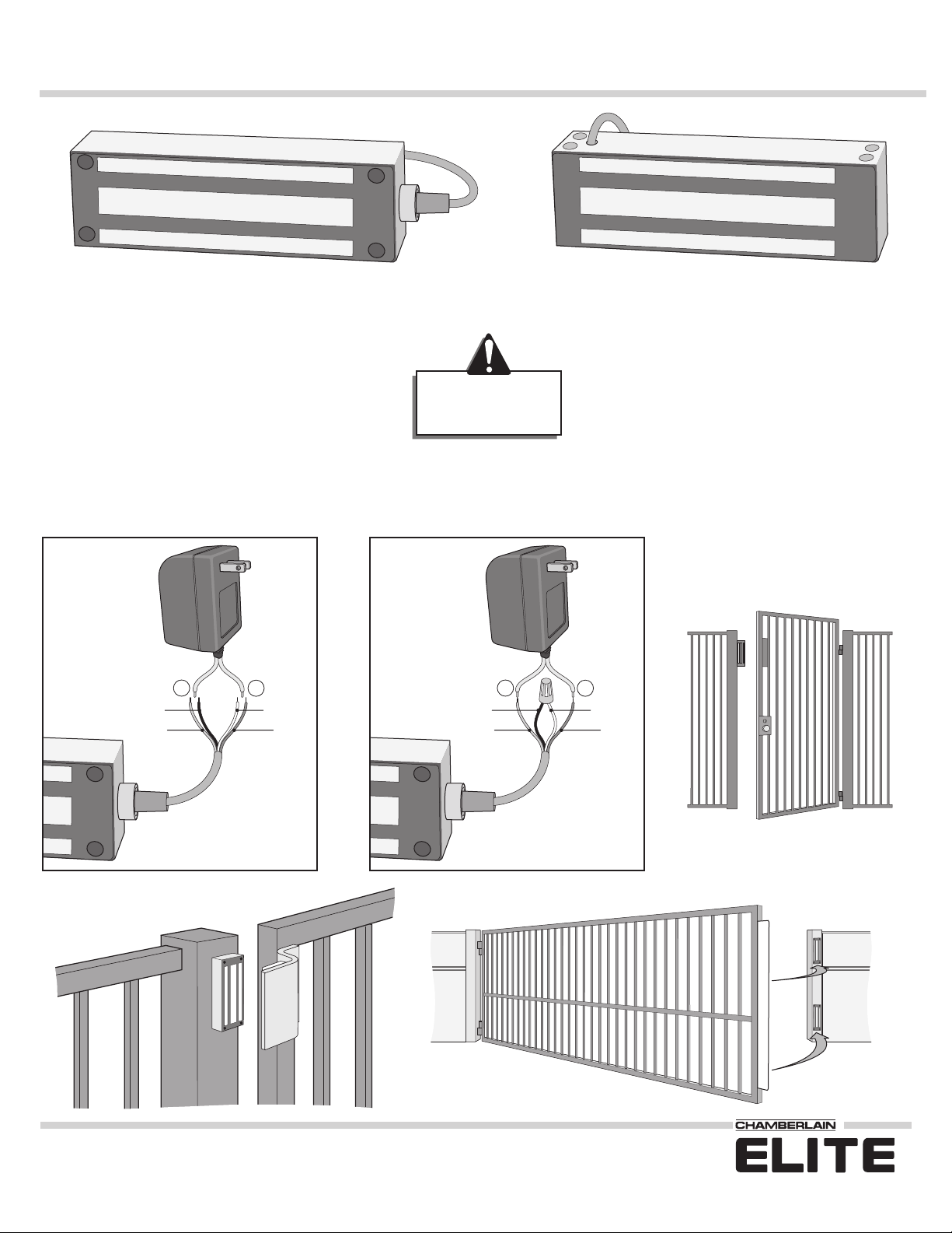
Wiring 12 VDC or 24 VDC Transformer (Not Included)
Model # EMLO 1300F
Face Mount Model # EMLO 1300F
Surface Mount
Model # EMLO 1300S
Model # EMLO 1300S
Specifications:
Specifications and Wiring for 1300F or 1300S
Do Not Use Wire
Smaller than
22 AWG
Current draw: 250 mA @
24 V
, 500 mA @
12 V
Housing:
Plating:
Power Supply:
Stainless Steel
Zinc
12 VDC Supply:
Transformer: input 120 Vac, output: 7.2 VA 12 VDC @ 600mA
24 VDC Supply:
Transformer: input 120 Vac, output: 14.4 VA 24 VDC @ 600mA
If power supply is
12 VDC
and wire is 50 ft use 18 AWG, if wire is 150 ft use 14 AWG.
If power supply is
24 VDC
and wire is 50 ft use 22 AWG, if wire is 150 ft use 18 AWG.
Handling Maglock:
The electromagnetic lock and armature are ruggedly constructed
and designed to provide years of trouble free service. Care must be
taken during installation and during actual use so that the lock face
and the armature face are free of dirt, rust, burrs, paint, or any other
obstruction which may interfere with the lock and armature making
good contact.
Mounting Maglock:
The lock must mount rigidly to the gate/door frame, and the
armature must mount to the gate/door. (See reverse side).
Maintenance of Maglock:
To insure peak lock performance, clean the lock
and armature faces with a mild detergent and a
clean soft cloth. Then apply a light coat of rust
inhibitor, such as WD40, to lubricate and protect
these surfaces. This need only be done when dirt
build-up is noticed.
White
Green
Black
Red
–
+
12 VDC
@ 500 mA
Transformer
Not Included
12 VDC
Face Mount Surface Mount
For Technical Support: 1-800-528-2806
®
™
Page 2
Rubber
Washer
Armature
Screw
Tool
Washer
Cap Screw
Allen
Wrench
Wrench
Armature
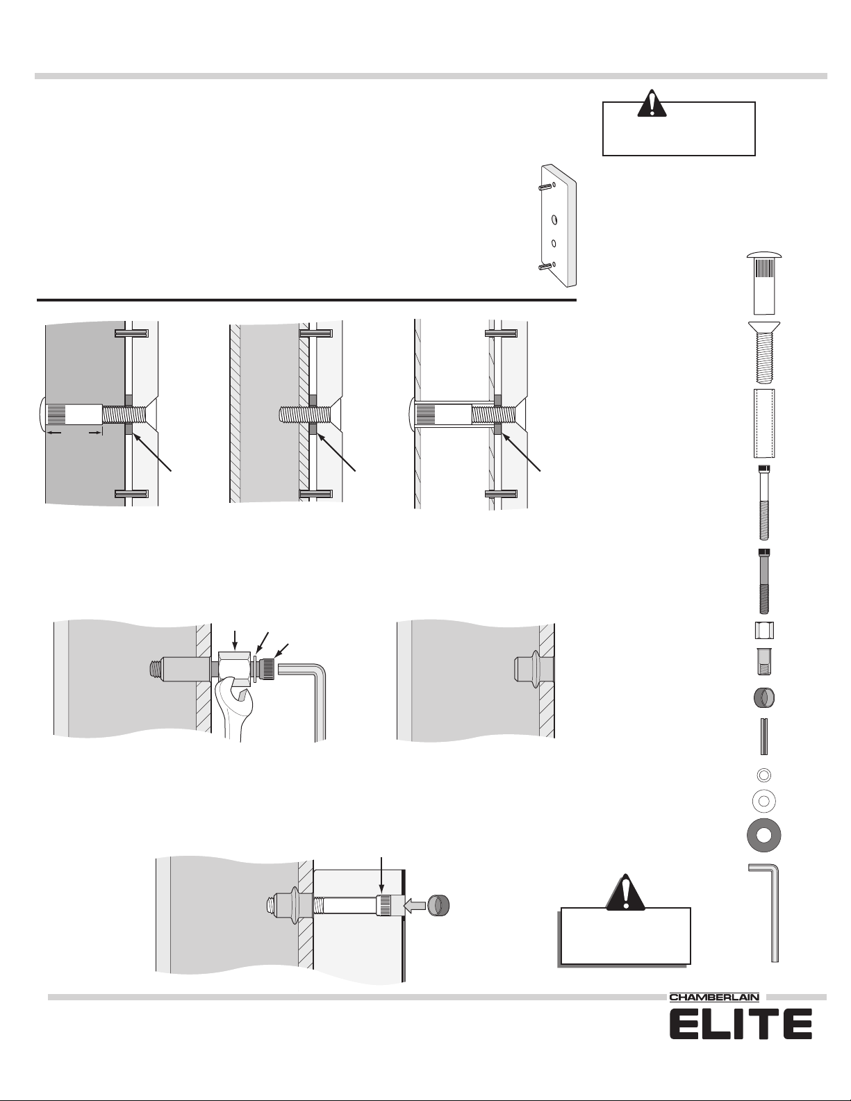
Types of Door/Gate Armature Attachments
Hardware Parts List
1 1/2”
Guide Pin
Guide Pin
Sexnut Bolt
Sexnut Bolt
and
Door Spacer
Rubber
Washer
Armature
Screw
Armature
Door
or Gate
Door
or Gate
Door
or Gate
Guide Pin
Guide Pin
Rubber
Washer
Armature
Screw
Armature
Guide Pin
Guide Pin
STEP 1:
Determine position of Magnetic lock and Armature on gate/door and header/post. Use the template provided for the
Model to be installed. Transfer the position of the hole locations for both the Magnetic Lock and Armature.
STEP 2:
Mount Armature in accordance to Gate or Door type. (See illustrations below)
Install anti-spin guide pins in the back of the armature as shown to the right, this insures the
plate will not move after installation.
Be
precise
when marking
holes with template.
Anti-Spin Guide Pin
Anti-Spin Guide Pin
Armature
Mounting the Magnetic Lock and Armature
STEP 4:
Firmly tighten all screws through Magnetic Lock to application. Install anti-tamper plugs into holes covering
each sockethead mounting screw, use soft hammer to avoid damaging lock case. See illustration C. on opposite page.
Anti-Spin Guide Pin
Small Washer
Flat Washer
Rubber Washer
Allen Wrench
Anti-Tamper Plug
Tool
Sexnut Bolt
Armature Screw
Door Spacer
Blind Nut
Sockethead
Mounting Screw
Cap Screw
Drill a 9.3 mm (approx. 3/8") hole and press in
blind nut and hardware as shown.
Anti-Tamper Plug
Magnetic Lock
Sockethead Mounting Screw
Header
or Post
Be sure to collapse the blind nuts
before installing magnetic lock.
Collapsed
Blind Nut
Collapsed
Blind Nut
Note;
Use Locktite on
screw threads to avoid
the possibility of screws
loosening over time.
Drill a 16mm (approx. 11/16") hole
through gate/door. From sexnut bolt
side, insert door spacer.
Drill a 6.8mm (approx. 9/32")
hole
and tap for M8-12.25 thread.
Drill an 8mm (approx. 3/8") hole
through gate/door. From sexnut bolt
side only,
drill 1/2" hole
, 1 1/2"
depth.
Hollow
Door/Gate
Reinforced
Door/Gate
Solid
Door/Gate
See Reverse Side
for Wiring
Instructions
CAUTION!
Door
or
Gate Frame
Door
or
Gate Frame
STEP 3:
In order to mount the Magnetic lock, Blind nuts are included along with a tool to install them. The blind nut
collapses when cap screw is turned with Allen wrench and tool is held fast with box wrench. See illustration below. If
applicable, install all blind nuts.
01-50745B
For Technical Support: 1-800-528-2806
845 Larch Avenue Elmhurst, Illinois 60126
www.chamberlain.com
© 2005 The Chamberlain Group, Inc.
All Rights Reserved
®
™
 Loading...