

Page 1
LCD Kit Installation
© 2006, The Chamberlain Group, Inc.
114A3265 All Rights Reserved
for the EL2000 telephone entry/access control system
Caution!
A static discharge can
DAMAGE circuit boards.
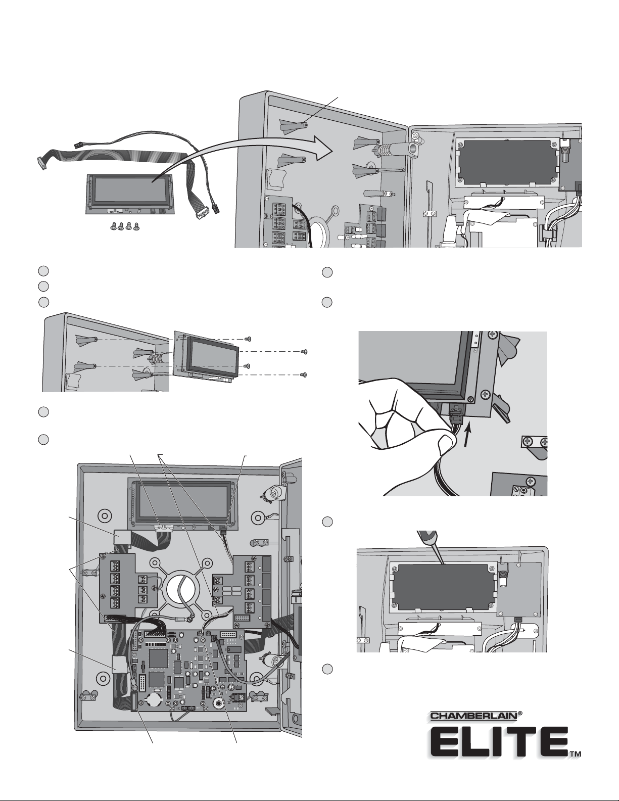
1
Disconnect power to the unit!
2
Unlock and open the unit.
Install LCD onto the four mounting posts.
3
Mounting Posts
Plug the small harness into the J1 connector on the LCD board
6
and into J500 connector on the main board.
Plug the large harness into the Gray connector on the LCD board
7
and into J300 connector on the main board.
Model ELLCDKT
Route the wire harnesses as shown, running them beneath the
4
input and output boards.
Slip the larger harness into the two wire retainers.
5
J401
J301
J404
IO Input Board
D300
J300
J3
J2
J1
POWER
12VAC/DC
J405
+
BT300
Small Wire Harness
RES
J6
TELCO
J8
H2
100A
UD
3D2
100
16B
J407
DEVICE 3,4
16B
100
3D2
J402 LEDJ200 SPKR
D514
D513
SW300
UV
OV
MIC
J201
J500
J406 LCD
H2
100A
UD
D102
D153
3D2
H2
3D2
100
100A
100
16B
UD
16B
3D2
J400
100
16B
DEVICE 1,2
D2
J1 Connector
IO Output Board
NO
LED 4
J5
NC
C
RELAY 4
NO
NC
J4
LED 3
C
RELAY 3
NO
J3
NC
C
LED 2
NO
RELAY 2
NC
J1
C
LED 1
RELAY 1
J403
Wire
Retainer
Large
Wire
Harness
Wire
Retainer
Gray Connector
EXIT
REQ 4
COM
DOOR
STAT 4
EXIT
REQ 3
COM
DOOR
STAT 3
EXIT
REQ 2
COM
DOOR
STAT 4
EXIT
REQ 1
COM
DOOR
STAT 1
J7
J6
POSTAL
AUTO
J5
J4
8
Pop black lens out of clear lens and discard.
9
Close and lock the unit. Connect power.
J300 Connector
J500 Connector
 Loading...