

Page 1
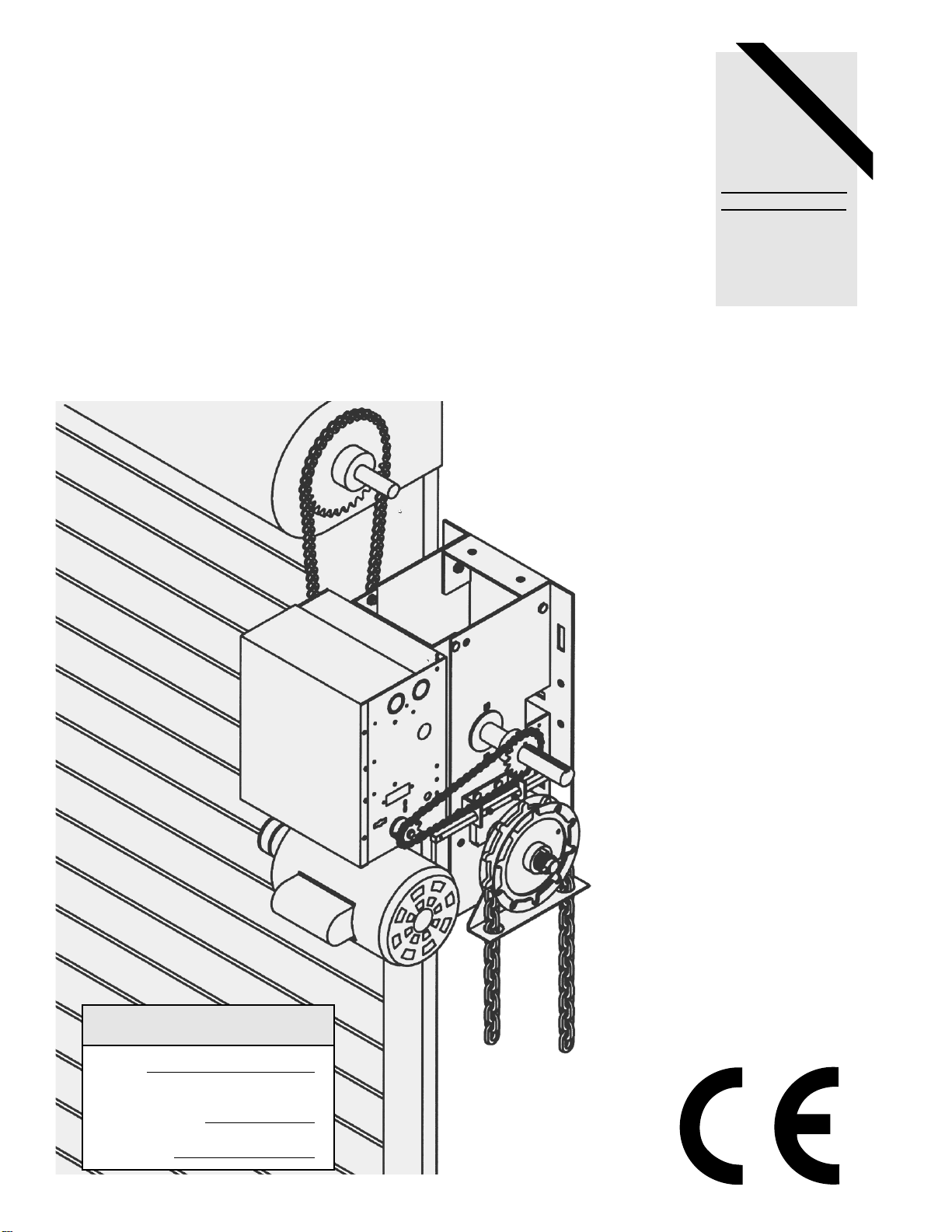
OWNER'S MANUAL
MODELS:
EJ & EH
LOGIC CONTROL (VER. 2.0)
INDUSTRIAL DUTY DOOR OPERATOR
Serial #
(located on electrical box cover)
Installation Date
Wiring Type
2 YEAR WARRANTY
LOGIC CONTROL
L
FACTORY SET
C2 Wiring
See pages 16 & 17
for other wiring
configurations
Page 2
2
IMPORTANT SAFETY NOTES
The force, as measured on the closing edge of
the door, should not exceed 150 N (15kg). If the
closing force is adjusted to more than 150 N,
additional entrapment protection devices must
be installed, see page #9 for matrix. Do not use
the force adjustments to compensate for a binding or sticking door. Excessive force will interfere
with the proper operation of the Safety Reverse
System or damage the door.
Fasten the caution label adjacent to the door con-
trol station as a reminder of safe operating procedures.
Disengage all existing door locks to avoid damage
to door. If the door lock needs to remain functional,
install an interlock switch.
Install the three button station, master disconnect switch and any additional controls in a
location where the door is visible, but out of the
reach of children. Do not allow children to operate push button(s) or remote control(s). Serious
personal injury from a closing door may result from
misuse of the opener.
CAUTION: Activate opener only when the door
is in full view, free of obstructions and opener is
properly adjusted. No one should enter or exit
through the door opening while the door is in
motion. Do not allow children to play near the
door.
Proper electrical lock-out/tag-out procedures
must be followed before making repairs or
removing covers on the door operator.
Keep door balanced. Sticking or binding doors
must be repaired. Doors, door springs, cables, pulleys, brackets and hardware are under extreme tension and can cause serious personal injury. Do not
attempt to loosen, move or adjust them. Call for
door service.
Proper protective gear should be worn when servicing or installing the door operator. Do not wear
rings, watches or loose clothing while installing or
servicing a door opener. Do wear safety glasses,
back support belt, and protective gloves. When
working on ladders and or elevated platforms, proper safety procedures must be followed.
To avoid serious personal injury from entanglement,
remove all ropes & chains connected to the
door before installing the door opener.
Installation and wiring must be in compliance with
your local building and electrical codes. Connect
the line power only to properly earthed mains.
This unit should not be installed in a damp or
wet space.
Only one (1) person is to perform work on the door
operator at a time.
All local safety regulations are to be applied when
working on the door operator.
Installation of this unit must be in accordance
with Per EN12453.
Before attempting to install, operate or maintain the operator, you must read
and fully understand this manual and follow all safety instructions.
These safety alert symbols mean Caution – a personal safety or property damage instruction. Read these
instructions carefully. This door opener is designed and tested to offer reasonable safe service provided it is
installed and operated in strict accordance with the following safety rules.
Failure to comply with the following instructions may result in serious personal injury or property damage.
Page 3

3
TABLE OF CONTENTS
WARNINGS
Safety Notes . . . . . . . . . . . . . . . . . . . . . . . . . . .2
OPERATOR SPECIFICATIONS
Packing List . . . . . . . . . . . . . . . . . . . . . . . . . . .3
Motor Specifications . . . . . . . . . . . . . . . . . . . . .4
Electrical Specifications . . . . . . . . . . . . . . . . . .4
Mechanical Specifications . . . . . . . . . . . . . . . . .4
Safety Specifications . . . . . . . . . . . . . . . . . . . . .4
Operator Weights and Dimensions . . . . . . . . . .4
DOOR OPERATING SYSTEM
Door Operator System Illustration . . . . . . . . . . .5
Factory Supplied Components List . . . . . . . . . .5
User Supplied Components List . . . . . . . . . . . .5
INSTALLATION PREPARATION
Lifting Specifications . . . . . . . . . . . . . . . . . . . . .6
Lifting Illustration . . . . . . . . . . . . . . . . . . . . . . . .6
Site Preparation . . . . . . . . . . . . . . . . . . . . . . . .6
Operator Preparation . . . . . . . . . . . . . . . . . . . .6
OPERATOR MOUNTING
Wall Mounting . . . . . . . . . . . . . . . . . . . . . . . . . .7
Bracket Mounting . . . . . . . . . . . . . . . . . . . . . . .7
Shelf Mounting . . . . . . . . . . . . . . . . . . . . . . . . .7
EMERGENCY MANUAL OPERATION
Model EH Manual Disconnect . . . . . . . . . . . . .8
Model EJ Manual Disconnect . . . . . . . . . . . . . .8
ENTRAPMENT PROTECTION (Optional)
Sensing Edges . . . . . . . . . . . . . . . . . . . . . . . . .9
Entrapment Protection Matrix . . . . . . . . . . . . . .9
POWER & CONTROL WIRING
Safety Notes . . . . . . . . . . . . . . . . . . . . . . . . . . .10
Specifications . . . . . . . . . . . . . . . . . . . . . . . . . .10
Power Wiring . . . . . . . . . . . . . . . . . . . . . . . . . .11
Control Wiring . . . . . . . . . . . . . . . . . . . . . . . . . .11
Ground Wiring . . . . . . . . . . . . . . . . . . . . . . . . .11
Push Button Illustration . . . . . . . . . . . . . . . . . . .11
Main/ Emergency Disconnect Illustration . . . . .11
Wiring Schematic . . . . . . . . . . . . . . . . . . . . . . .12
Electrical Box Illustration . . . . . . . . . . . . . . . . . .13
Limit Switch Adjustment . . . . . . . . . . . . . . . . . .14
PRINTED CIRCUIT BOARD SETTINGS
Program Settings . . . . . . . . . . . . . . . . . . . . . . .15
Wiring Types . . . . . . . . . . . . . . . . . . . . . . . . . . .16
Failsafe Wiring Types . . . . . . . . . . . . . . . . . . . .17
LED Indicator Readouts . . . . . . . . . . . . . . . . . .26
MECHANICAL ADJUSTMENT
Brake Adjustment . . . . . . . . . . . . . . . . . . . . . . .18
Clutch Adjustment . . . . . . . . . . . . . . . . . . . . . . .19
REPLACEMENT PARTS
Electrical Box Illustration . . . . . . . . . . . . . . . . . .20
Electrical Box Replacement Parts List . . . . . . .21
Model EJ Illustration . . . . . . . . . . . . . . . . . . . . .22
Model EJ Replacement Parts List . . . . . . . . . . .23
Model EH Illustration . . . . . . . . . . . . . . . . . . . . .24
Model EH Replacement Parts List . . . . . . . . . .25
MAINTENANCE OF OPERATOR
Maintenance Schedule . . . . . . . . . . . . . . . . . . .26
Technical Support . . . . . . . . . . . . . . . . . . . . . . .28
Parts Ordering Information . . . . . . . . . . . . . . . .28
PACKING LIST
DESCRIPTION QTY REFERENCE
Push Button Station 1 Figure 1 & 10
Chain Keeper 1 Figure 8
Hand Chain 1 Figure 1
Chain, #50 x 106 Pitches 1 Figure 1
Label, Maintenance Alert 1 Figure 10
Label, Door Edge Caution 1 Figure 1
Label, Entrapment Warning 1 Figure 1 & 10
Label, Master Disconnect 1 Figure 1& 10
Key 1 Figure 1
Door Sprocket 1 Figure 1
DESCRIPTION QTY REFERENCE
Push Button Station 1 Figure 1 & 10
Key Hole Bracket 1 Figure 9
Chain, #50 x 106 Pitches 1 Figure 1
Label, Maintenance Alert 1 Figure 10
Label, Door Edge Caution 1 Figure 1
Label, Entrapment Warning 1 Figure 1 & 10
Label, Master Disconnect 1 Figure 1 & 10
Key 1 Figure 1
Door Sprocket 1 Figure 1
MODEL EH5025L2 (Left or Right) MODEL EJ5025L2
Before beginning your installation check that all components were supplied and received undamaged. Refer to list
below for Factory Supplied parts.
Page 4
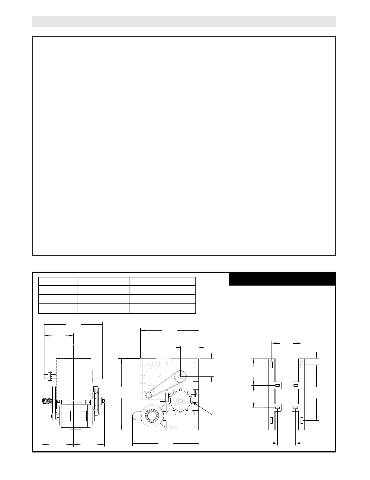
4
368mm
(14.50")
185mm
(7.25")
203mm
(8.00")
A
371mm
(14.60")
112mm
(4.41")
118mm
(4.63")
419mm
(16.50")
448mm
(17.63")
191mm
(7.50")
168mm
(6.63")
140mm
(5.50")
349mm
(13.75")
38mm
(1.50")
121mm
(4.75")
A
A
B
B
A
B
B
A
MOTOR
TYPE: .................................Continuous duty
HORSEPOWER: .....................375 W (1/2 Hp) Single phase
SPEED:...............................1425 RPM
VOLTAGE: ..........................230V/50Hz Single phase
CURRENT:..........................4.0 A
MECHANICAL
RATED POWER: ................190 W
DRIVE REDUCTION: .........Primary: Heavy duty (5L)
V-Belt. Secondary: #48 chain/sprocket. Output: #50
chain
OUTPUT SHAFT SPEED:.....34 R.P.M.
DOOR SPEED: ...........................150-180mm (6 - 7”) per
sec.
depending on door
BRAKE: .................................Solenoid actuated disc
brake
BEARINGS: ...........................Output Shaft: Shielded
Ball Bearing. Clutch Shaft: Iron Copper sintered and
oil impregnated.
HAND CHAIN WHEEL: .........Left or right handing
Model EH only.
WORKING ENVIRONMENT
: Indoor and Dry
Environment use only.
OPERATOR SPECIFICATIONS
ELECTRICAL
TRANSFORMER:.............24VAC Secondary
CONTROL STATION: ......NEMA 1 three button station.
OPEN/CLOSE/STOP W/ LED
WIRING TYPE:.................C2 (Factory Shipped)
Momentary contact to OPEN & STOP, constant pressure to CLOSE, open override plus wiring for sensing
device to reverse. See pages 16 and 17 for optional
wiring types and operating modes.
LIMIT ADJUST: ................Linear driven, fully
adjustable screw type cams. Adjustable to 7.3M (24 ft.)
SAFETY
DISCONNECT :
Model EJ: Floor level disconnect for emergency manual
door operation.
Model EH: Floor level chain hoist with electrical interlock
for emergency manual door operation.
REVERSING EDGE:......(Optional) Electric or pneumatic
sensing device attached to the bottom edge of door.
A REVERSING DEVICE IS STRONGLY RECOMMENDED FOR ALL COMMERCIAL OPERATOR
INSTALLATIONS. REQUIRED WHEN THE 3 BUTTON
CONTROL STATION IS OUT OF SIGHT OF DOOR
OR ANY OTHER CONTROL (AUTOMATIC OR MANUAL) IS USED. SEE MATRIX ON PAGE 9.
PHOTO EYES:...............Interface directly to LiftMaster
CPSII.
MOUNTING DIMENSIONS
A - Wall Mounting
B - Bracket Mounting (rolling door)
WEIGHTS AND DIMENSIONS
Hand Chain Wheel
present with Model
EH.
MODEL DIMENSION “A” WEIGHT
EH5025L2R 191mm (7.50”) 43.1 Kg. (95 Lbs.)
EH5025L2L 191mm (7.50”) 43.1 Kg. (95 Lbs.)
EJ5025L2 101mm (4.00”) 39.5 Kg. (87 Lbs.)
Page 5
5
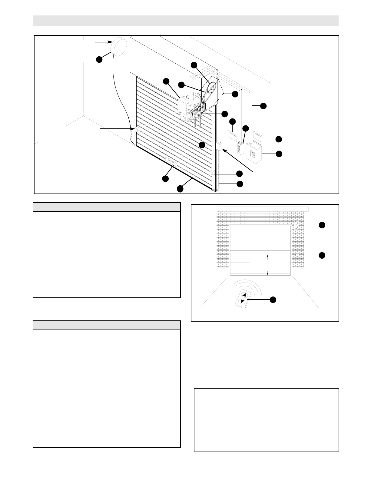
DOOR OPERATING SYSTEM
Qty
1
1
1 Ea.
1
1
1
1
1
1
1
Item
1
2
3
4
5
6
7
8
9
10
Description
Operator Power Head
Drive Chain
Door Sprocket & Key
Hoist Chain
Chain Keeper (See Page 8, Figure 8)
Keyhole Bracket (See Page 8, Figure 9)
3 Button Station
Entrapment Waring Label
Main/ Emergency Disconnect Warning Label
Door Edge Caution Label
FACTORY SUPPLIED COMPONENTS
USER SUPPLIED COMPONENTS
1
3
7
2
4
8
9
C
F
E
P
H
J
L
K
FIGURE 2 (VIEW FROM OUTSIDE)
FIGURE 1 (VIEW FROM INSIDE)
Qty
1
1
1
AR
1
1
1
1 Set
1
1
1
1
1
1
Item
A
B
C
D
* E
F
G
H
J
K
L
M
N
P
Description
Shaft Support Bracket (See Page 6, Figure 3)
Mounting Bracket (See Page 7, Figure 6)
Main/ Emergency Disconnect
Mounting Hardware
Guards (Chain & Belt)
Electrical Conduit & Wiring
Electric Safety Edge
Photo Eyes
Remote Control
Key Switch
Traffic Light
Coil Cord
Take-up Reel
Junction Box
1219 mm (4 Ft.)
MINIMUM
Mount Approximately
305mm (12”) above top
of door.
Mount 102-152mm (4-6”)
above bottom of door. Do
not exceed 152mm (6”)
Mount approximately
halfway up door opening.
G
N
M
10
It is the installers responsibility to guard all moving
chains, sprockets and pinch points at installation. It
is recommended that fixed guards be used to protect
against components which may become dislodged
in the event of a failure. If a complete enclosure is
used the cover should provide a minimum of 1016
mm (40 In ) of ventilation.
*
WHEN ORDERING REPAIR PARTS AND ACCESSORIES
ADDRESS ORDER TO:
CHAMBERLAIN GmbH
Alfred-Nobel-Str. 4
66793 Saarwellingen
PHONE ORDER: FAX ORDER:
(49) 6838-907105 (49) 6838-907239
TECHNICAL HOTLINE:
(49) 6838-907171
Page 6
6
SITE PREPARATIONS
It is imperative that the wall or mounting surface provide adequate support for the operator.
This surface must:
a) Be rigid to prevent play between operator and
door shaft.
b) Provide a level base.
c) Permit the operator to be fastened securely,
with the drive shaft parallel to the door shaft.
The safety and life of the operator will be adversely
affected if any of the above requirements are not met.
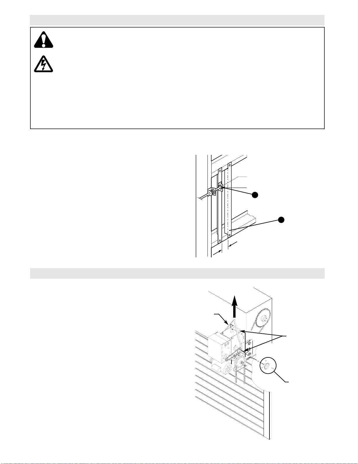
For metal buildings, fasten 50mm x 50mm x 5mm (2”
x 2” x 3/16”) (or larger) angle iron frames to the building purlins. Retain 140mm (5-1/2”) between frames.
See Figure 3.
Both EJ and EH series operators have dual output
shafts and may be mounted on either the right (standard) or left side of door, and in either a vertical (standard) or horizontal mounting position. If you need to
move the drive sprocket, loosen BOTH set screws,
remove the sprocket and key, and place on the opposite side of the drive shaft. Be sure to tighten BOTH
set screws securely
Hand Chain Handing
For model EH with manual hoist hand chain systems,
the handing of the operator must be determined at the
time of order. The handing is indicated by last letter of
the model name (R or L). The hand chain wheel can
not be switched on site. If your installation causes
the hand chain to hang in the door opening, hook the
chain off to the side near the top of the door jamb.
OPERATOR PREPARATION
140mm
(5-1/2”)
Door Requirements: Door must be balanced within 150N and must have mechanical fixed stops at the end
points of travel
FIGURE 3
A
D
The weight of this operator powerhead is excessive, and can cause severe injury upon lifting, installing
or dislodging from its mounted position.
The operator powerhead should be raised into its mounting position by use of a hoist or elevated platform. Acceptable lifting points are output shaft or chassis frame. Do not lift by electrical enclosure. The
unit should be secured to the lifting apparatus to prevent it from swaying or dislodging during installation. The unit should be fastened to its mounting surface with the correct size and grade hardware. All
mounting hardware should be securely fastened before releasing supporting devices. (See figure 4 on
page 6 for proper lifting).
The above stated procedures must be followed in the event that the unit is to be removed from
its mounted position when servicing is required.
Drive Sprocket (1)
Key (1)
Set Screw (2)
FIGURE 4
LIFT
Approved Lifting
Points (Output
Shaft and Frame)
Suitable Strap
or Chain
Shaft Support Bracket
with Bearing (Not Supplied)
Door Sprocket
2-1/4"
FIGURE 1
Page 7
7
1a. Wall Mounting
The operator should generally be installed below
the door shaft, and as close to the door as possible. The optimum distance between the door shaft
and operator drive shaft is between 305-380mm
(12 - 15”). Refer to Figure 5.
OPERATOR MOUNTING
IMPORTANT:
The shelf or bracket must provide adequate support, prevent play between operator and door
shaft, and permit operator to be fastened securely, with
the drive shaft parallel to the door shaft.
1b. Bracket or Shelf Mounting
The operator may be mounted either above or
below the door shaft. The optimum distance
between the door shaft and operator drive shaft is
between 305-380mm (12 - 15”).
Refer to Figure 6.
1c. Place door sprocket on the door shaft. Do not
insert the key at this time.
2. Place drive sprocket on the appropriate side of the
operator. Do not insert the key at this time.
3. Wrap drive chain around door sprocket and join
roller chain ends together with master link.
4. Raise operator to approximate mounting position
and position chain over operator sprocket.
5. Raise or lower operator until the chain is taut (not
tight). Make sure the operator output shaft is parallel to door shaft and sprockets are aligned. When
in position, secure the operator to wall or mounting
bracket.
6. Align sprockets and tighten all set screws and
mounting hardware. (see Figure 7).
FIGURE 6
FIGURE 5
Before your operator is installed, be sure the door has been properly aligned and is working smoothly. The operator may be wall mounted or mounted on a bracket or shelf. Refer to the operator preparations on page 6. Refer
to the illustration and instructions below that suits your application.
NOTE
Mounting Hardware: Minimum (4) M8, Grade 5 Bolts.
Electrical Connections: All fittings and conduit connections must meet local electrical code requirements.
FIGURE 7
Typical Right Hand
Wall Mounted Operator
Optimum Distance
305-380mm (12 - 15”)
OPTIONAL
Mounting Bracket
P/N 08-9098
Be sure door
sprocket is properly aligned with
drive sprocket
before securing to
the shaft.
Chain Keeper
2.5M Minimum
(8.2’ Minimum)
FLOOR
FLOOR
Optimum Distance
305-380mm (12 - 15”)
B
2.5M Minimum
(8.2’ Minimum)
Page 8
8
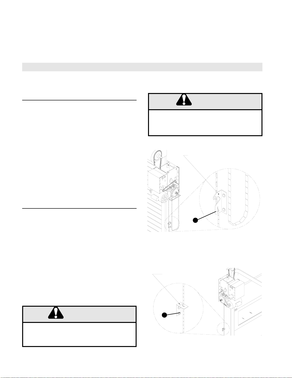
These operators are equipped with a manual hoist. An
electrical interlock will disable the electrical controls
when the hoist is used. To operate the hoist:
1. Pull the disconnect chain (small chain) to engage the
hoist mechanism. The disconnect chain may be locked
in position by slipping the end through the keyhole of
the chain keeper mounted on the wall.
2. Operate the door in the desired direction by pulling
on one side or the other of the continuous loop hoist
chain (large chain).
3. The disconnect chain must be released from the
chain keeper before the door will operate again electrically.
7. Install Hand Chain (Model EH) Place hand
chain around hand chain wheel. Be sure to pass
it through both openings in the chain guide.
Remove enough links so chain hangs approximately 609mm (24”) above the floor.
EMERGENCY MANUAL OPERATION
This operator has provisions for manually operating the door in case of an emergency or power failure. Refer to
the appropriate instructions below for your model operator.
Model EH
Model EJ
This operator has a floor level disconnect chain to disconnect the door from the door operator. An electrical
interlock will disable the electrical controls when the
operator is disengaged.
1. To disengage, pull the chain and secure in the dis-
engaged position by slipping the end through the keyhole bracket mounted on the wall. Or if emergency
egress device is used, pull handle to disengage operator from door.
2. The door may now be pushed up or pulled down
manually. Release the disconnect chain to operate the
door again electrically.
8. Mount Chain Keeper / Keyhole Bracket
Using suitable hardware mount the chain keeper
approximately 1219mm (48”) above the floor, near
the free hanging chain. Remove disconnect sash
chain from bag and place the end through the keyhole in the the chain keeper. Remove excess links
if necessary.
Manual Disconnect for Model EJ
Electrical Interlock with Hoist for Model EH
LOCK-OUT ELECTRICAL POWER TO THE OPERATOR VIA, THE MAIN/ EMERGENCY DISCONNECT
BEFORE MANUALLY OPERATING YOUR DOOR.
WARNING
CAUTION
WARNING
WARNING
Chain Keeper
(with pad locking provisions)
Keyhole Bracket
FIGURE 8
5
FIGURE 9
7
WHEN USING THIS OPTION THE OPERATOR IS NOT
AUTOMATICALLY ELECTRICALLY INTERLOCKED.
WARNING
CAUTION
WARNING
Page 9
9
ENTRAPMENT PROTECTION ACCESSORIES (OPTIONAL)
SENSING EDGES
If not pre-installed by the door manufacturer, contact
you local LIFTMASTER Dealer for available sensing
edges.
Mount the sensing edge on the door according to the
instructions provided with the edge. The sensing
edge may be electrically connected by either coiled
cord or take-up reel. Refer to the steps below.
Important Notes:
a) Proceed with Limit Switch Adjustments before
making any sensing edge wiring connections to
operator as described below.
b) Electrician must hardwire the junction box to the
operator electrical box in accordance with local
codes.
TAKE-UP REEL: Take-up reel should be installed
approximately 305mm (12”) above the top of the
door.
COIL CORD: Connect operator end of coil cord to
junction box (not supplied) fastened to the wall
approximately halfway up the door opening.
IT IS STRONGLY RECOMMENDED THAT A
SENSING EDGE OR OTHER ENTRAPMENT
PROTECTION DEVICE BE USED IN CONJUNCTION WITH THIS OPERATOR. SEE INSTALLATION MATRIX FOR INSTALLATIONS WHICH
REQUIRE THE USE OF SENSING EDGES.
ENTRAPMENT PROTECTION MATRIX
z A: Hold to run control push button.
z B: Hold to run control with key switch or similar.
z C: Limitation of operating forces with force limiting devices (clutch) & safeguarding (safety edge)
z D: Device for the detection of the presence of a person or an obstacle standing on the floor at one side
(inside) of the door. (Infrared Eyes).
z E: Device for the detection of the presence of a person or an obstacle standing on the floor at both sides
(inside & outside) of the door leaf. (Infrared Eyes).
NOTE: For detailed access information refer to Per EN12453.
Hold to Run Control
Impulse Activation in Sight of the
Door
Automatic Control
Trained Users
(No Public)
Group 1
A
C
C and D
Trained Users
(Public Area)
Group 2
B
C and D
C and E
Trained Users
(General Public Area)
Group 3
N/A
C and E
C and E
WHEN ORDERING REPAIR PARTS AND ACCESSORIES
ADDRESS ORDER TO:
CHAMBERLAIN GmbH
Alfred-Nobel-Str. 4
66793 Saarwellingen
PHONE ORDER: FAX ORDER:
(49) 6838-907105 (49) 6838-907239
TECHNICAL HOTLINE:
(49) 6838-907171
TYPE OF CONTROLS DOOR USE
Page 10

10
DISCONNECT POWER AT THE FUSE BOX BEFORE
PROCEEDING.
OPERATOR MUST BE PROPERLY GROUNDED AND
CONNECTED IN ACCORDANCE WITH LOCAL ELECTRICAL CODES. NOTE: THE OPERATOR SHOULD
BE ON A SEPARATE FUSED LINE OF ADEQUATE
CAPACITY.
ALL ELECTRICAL CONNECTIONS MUST BE MADE
BY A QUALIFIED INDIVIDUAL.
WARNING
TO AVOID DAMAGE TO DOOR AND OPERATOR,
MAKE ALL DOOR LOCKS INOPERATIVE. SECURE
LOCK(S) IN "OPEN" POSITION.
IF THE DOOR LOCK NEEDS TO REMAIN FUNCTIONAL, INSTALL AN INTERLOCK SWITCH.
WARNING
INSTALL ALL CONTROL STATIONS NO FURTHER
THAN 305mm (12”) FROM THE DOOR ENCLOSURE.
IF THE CONTROL STATION CANNOT BE INSTALLED
AT THIS DISTANCE, A REVERSING EDGE MUST
BE
INSTALLED ON THE BOTTOM OF THE DOOR. FAIL-
URE TO INSTALL A REVERSING EDGE UNDER
THESE CIRCUMSTANCES MAY RESULT IN SERIOUS
INJURY OR DEATH TO PERSONS TRAPPED
BENEATH THE DOOR.
Before installing power wiring or control stations be sure to follow all specifications and warnings described below. Failure to do so may result in severe injury to persons and/or damage to
operator.
The operator electrical box is only to be accessed by trained “LIFTMASTER” technicians. If service is required contact your local LIFTMASTER dealer.
Do not install any wiring or attempt to run the operator without consulting the wiring diagram.
Install the optional Reversing Edge before proceeding with the Control Station installation.
IMPORTANT SAFETY NOTES
INSTALL POWER WIRING & CONTROL STATION
ANY MAINTENANCE TO THE OPERATOR OR IN THE
AREA NEAR THE OPERATOR MUST NOT BE PERFORMED UNTIL DISCONNECTING THE ELECTRICAL POWER AND LOCKING-OUT THE POWER VIA,
THE MAIN DISCONNECT SWITCH. UPON COMPLETION OF MAINTENANCE THE AREA MUST BE
CLEARED AND SECURED, AT THAT TIME THE UNIT
MAY BE RETURNED TO SERVICE.
MAIN/ EMERGENCY DISCONNECT
Minimum rating for a Main/ Emergency Disconnect
Switch: 600 VAC , 16.0 A, 1 phase, 1 normally closed
auxiliary contact switch must comply with EN (IEC)
60947.
POWER & CONTROL
WIRES
Must be run in ducting meeting (IP 33 minimum) or be
suitably protected (double insulation, sufficient HAR rating). The minimum cross sectional area 2.5 mm .
For all other control and safety accessories contact
you local LIFTMASTER dealer.
SUGGESTED MAIN/ EMERGENCY DISCONNECT & WIRING SPECIFICATIONS
NOTE: All electrical wiring must pertain to local electrical codes.
2
WHEN ORDERING REPAIR PARTS AND ACCESSORIES
ADDRESS ORDER TO:
CHAMBERLAIN GmbH
Alfred-Nobel-Str. 4
66793 Saarwellingen
PHONE ORDER: FAX ORDER:
(49) 6838-907105 (49) 6838-907239
TECHNICAL HOTLINE:
(49) 6838-907171
WARNING
WARNING
WARNING
WARNING
Page 11

11
POWER WIRING CONNECTIONS
1. Connect power wires coming from the main/ emergency disconnect to the captive terminal block in the
electrical box enclosure marked with the label shown
below.
2. Be sure to run all power wires through the conduit
hole in the electrical box enclosure marked with the label
shown below.
POWER WIRING
CONTROL STATION WIRING
CONTROL WIRING CONNECTIONS
1. Connect control wires to the TB1 terminal block
located on the Printed Circuit Board (shown below).
2. Be sure to run all control wires through the conduit
hole in the electrical box enclosure marked with the label
shown below.
3. Apply power to the operator. Press OPEN push button and observe direction of door travel and then Press
the STOP button.
If door did not move in the correct direction, check for
improper wiring at the control station or between operator and control station.
For Control Station and Main/ Emergency Disconnect
mounting refer to figure 10 below.
GROUND WIRING
1. Connect earth ground to chassis ground screw in the
electrical box enclosure marked with the label shown
below.
2. Use same conduit entry into the electrical box as the
power wiring.
4 ft. (1219mm)
(Approximate)
1. Mount Control Station and Main/ Emergency
Disconnect no further than 305mm (12”) from
each other.
2. Mount Control Station and Main/ Emergency
Disconnect no further than 305mm (12”) from
the door enclosure.
3. Mount WARNING NOTICE beside or below
the Control Station and Main/ Disconnect.
4. Mount MAINTENANCE ALERT label to
either side of control station.
MOUNTING INSTRUCTIONS
FIGURE 10
Control
Station
Main
Disconnect
L1 L2 L3
40-16308A
40-10033B
PROGRAMMING OPTIONS IN THE OPERATOR
OR IN THE AREA NEAR THE OPERATOR MUST
MAINTENANCE THE AREA MUST BE CLEARED
AND SECURED, AT THAT TIME THE UNIT MAY
ANY MAINTENANCE OTHER THAN
NOT BE PERFORMED UNTIL DISCONNECTING
THE ELECTRICAL POWER AND LOCKING-OUT
THE POWER VIA, THE MAIN DISCONNECT
SWITCH. UPON COMPLETION OF
BE RETURNED TO SERVICE.
Maintenance Alert
TM
System
If light is Flashing,
it is time for routine
Door and Opener
Maintenance.
If light is Steady
On, call for
immediate service.
Service every
________ cycles.
Page 12

12
RADIO (24V)
LOGIC CONTROL (VER. 2.0) 1 PH WIRING SCHEMATIC
1874-1
R1 R3
(BR)
AUXILIARY CLOSE
LIMIT SWITCH
125/24VAC 10 A
(WH)
(WH)
(WH)
R2
(GY/WH)
(YE)
(GY)5V(YE)N(RD)N(WH)
28VNN
TO RPM
SENSOR
(YE)
OPEN LIMIT
SWITCH
125/24VAC 10 A
(BL)
CLOSE LIMIT
SWITCH
125/24VAC 10 A
(RD)
N
(WH) 5V
3241 1234 4321
P4 P5 P6
POWER PHASE JUMPER IN 1PH POSITION
SINGLE PHASE
CONTACTOR/ 3 PHASE
1 BUTTON
STATION (OPTIONAL)
TB1
1
2345678910111213
SENSING DEVICE
(YE)
INTER.
SWITCH
(YE)
24VAC
STOP
3 BUTTON
STATION (5V)
CLOSE
OPEN
E14 E9
(YE)
(OR)
N
TRANSFORMER
(240VAC PRIMARY
24VAC SECONDARY
N
SECONDARY
50/60HZ 40VA)
PRIMARY
(OR)
(BK)
230V
E19
(GN/YE)
E12
(RD)
E2
L3 L2 L1
(GN/YE)
LINE FILTER
(250VAC 10A)
L3 L2 L1
(YE)
(BK)
N
N1 P1
NPE
(BK)
N
(BK)
N
E13
E4
E17
E15
E10
E5
E1
E11
(RD)
230V
(RD)
230V
TERMINAL BLOCK
(RD)
230V
(BK) 230V
(YE) N
(BL) 230V
(BL/BK) 230V
(BL/BK) N
(BK) 230V
(BK) N
(600V)
TO MOTOR
(1/2HP 230V/50HZ 1PH)
BRAKE SOLENOID
(240V)
OVERLOAD
(250VAC 32VDC 6A)
KEY SWITCH
(OPTIONAL)
MAINTENACE ALERT LED
EMERGENCY
STOP
PE
L1N
FUSED POWER IN
(230V 50HZ 1PH)
MAIN/ EMERGENCY
DISCONNECT
(600VAC 16A)
Page 13

13
ELECTRICAL BOX COMPONENT LOCATION
The operator electrical box is only to be accessed by trained “LIFTMASTER” technicians. If service is required contact your local LIFTMASTER dealer.
SWITCH BEFORE REMOVING COVER.
POWER VIA, MAIN DISCONNECT
ELECTRICAL POWER AND LOCK-OUT
ELECTROCUTION, DISCONNECT
INJURY OR DEATH FROM
TO AVOID SERIOUS PERSONAL
HIGH VOLTAGE
COVER LABEL
HIGH VOLTAGE
COVER
TB1 TERMINAL
BLOCK
GROUND
SCREW
PRINTED CIR-
CUIT BOARD
CAPTIVE TERMINAL
BLOCK
230V/50Hz 1PH
WARNING
40-16307A
Page 14

14
LIMIT SWITCH ADJUSTMENT
FIGURE 11
The operator electrical box is only to be accessed by trained “LIFTMASTER” technicians. If service is required contact your local LIFTMASTER dealer.
TO AVOID SERIOUS PERSONAL INJURY OR DEATH
FROM ELECTROCUTION, DISCONNECT ELECTRIC
POWER BEFORE MANUALLY MOVING LIMIT NUTS.
WARNING
MAKE SURE THE LIMIT NUTS ARE POSITIONED BETWEEN THE LIMIT SWITCH ACTUATORS BEFORE
PROCEEDING WITH ADJUSTMENTS. (Limit switch adjustments are located on the front wall of the electrical enclosure, see figure below)
1. To adjust limit nuts depress retaining plate to allow
nut to spin freely. After adjustment, release plate
and ensure it seats fully in slots of both nuts.
2. To increase door travel, spin nut away from actu-
ator. To decrease door travel, spin limit nut toward
actuator.
3. Adjust open limit nut so that door will stop in open
position with the bottom of the door even with top
of door opening.
4. Repeat Steps 1 and 2 for close cycle. Adjust close
limit nut so that actuator is engaged as door fully
seats at the floor.
WHEN ORDERING REPAIR PARTS AND ACCESSORIES
ADDRESS ORDER TO:
CHAMBERLAIN GmbH
Alfred-Nobel-Str. 4
66793 Saarwellingen
PHONE ORDER: FAX ORDER:
(49) 6838-907105 (49) 6838-907239
TECHNICAL HOTLINE:
(49) 6838-907171
CUT-AWAY VIEW OF ELECTRICAL BOX
WARNING
OPEN
LIMIT SW.
LIMIT
NUT
DEPRESS
PLATE
CLOSE
LIMIT SW.
ROTATOR
CUP
RPM
BOARD
SAFETY
LIMIT SW.
Page 15

15
Open
Close
Stop
Single Button
Control Station
Adds 5 seconds to countdown timer.
Resets the timer to close to 0 seconds.
Turns off electronic search for photo eyes after photo eyes
have been intentionally removed.
Adds 5 seconds to “Red warning light before closing”
time.
Adds 60 seconds to countdown timer.
Press This Button To Get This Result
PROGRAM SETTINGS
Logic Control Pushbuttons Open, Close, Stop
Open, Close and Stop buttons are mounted directly on the Logic Control board. This will provide easy programming ability and door control at the electrical box.
M
Figure 1
Maintenance
Alert LED
Programmable Mid-stop:
The system will learn a programmable Mid-Stop point and will stop at that point whenever the door is opened from a fully closed position.
Setting Mid-Stop:
Start with the door in the fully closed position. Set DIP switches to “set mid-stop”
mode. Press the open button. When the door reaches the desired Mid point, press
the stop button. Set DIP switches to the desired operating mode (B2, C2, T, TS,
FSTS). Press the open button and allow the door to run to the open limit.
Clearing Mid-Stop:
Start with the door in the fully closed position. Set DIP switches to “set mid-stop”
mode. Press the open button. Allow the door to run to the open limit. Set DIP switches to the desired operating mode (B2, C2, T, TS, FSTS).
Programmable Maximum Run Timer:
Any time a “closing” or “opening” door takes 10 seconds longer than its programmed
normal cycle time, the door will stop. The factory default for maximum run time is 90
seconds.
Setting Maximum Run Timer:
Start with the door in the fully closed position. Set DIP switches to “set max run timer”
mode. Press the open button. Allow the door to run to the open limit. Once the door
has stopped, set DIP switches to the desired operating mode (B2,C2, D1, E2, T, TS,
FSTS). The maximum run time is now set to the door’s travel time + 10 seconds.
Maintenance Alert System
Set dip switch to set cycle counter mode. When the operator is in this mode the LED
will flash the number of times in 5k increments the operator has cycled followed by a
five second delay.
(Refer to figure 1 for LED location on the pushbutton).
Open
Close
Stop
Adds 5,000 cycles to Maintenance Alert System Activation
Counter
Clears memory, sets Maintenance Alert System Activation
Counter to 0 cycles.
Adds 10,000 cycles to Maintenance Alert System Activation
Timer
Press This Button To Get This Result
Set Timer to Close (CPSII Required)
Begin with the door in the closed position. Set dip switch to “Set Timer to Close”.
l The Maintenance Alert System LED will light when you press button.
l The Timer to Close only works in T, TS, and FSTS wiring modes with a CPSII.
When the door has cycled the number of times you set, the Maintenance Alert System
LED will flash once every second until the unit is serviced and the cycle counter is
cleared.
ON
ON
SET
MAX RUN
TIMER
1 2 3 4
OFF
ON
ON
AINTENANCE
ALERT
SYTSTEM
1 2 3 4
OFF
MIDSTOP
SET
TIMER
TO CLOSE
ON
ON
SET
1 2 3 4
OFF
ON
ON
1 2 3 4
OFF
Page 16

16
WIRING TYPES
WIRING
TYPE STATION
C2 3 Button, 3 Button Radio Control
Function
: Momentary contact to open and stop with constant pressure to close, open
override plus wiring for sensing device to reverse.
B2 3 Button, 1 Button, 1 & 3 Button Radio Control
Function: Momentary contact to open, close and stop, plus wiring for sensing device to
reverse and auxiliary devices to open and close with open override.
D1 2 Button, 3 Button Radio Control
Function
: Constant pressure to open and close with wiring for sensing device to stop.
E2 2 Button, 3 Button Radio Control
Function
: Momentary contact to open with override and constant pressure to close.
Release of close button will cause door to reverse (roll-back feature) plus wiring for
sensing device to reverse.
T* 3 Button, 1 Button, 1 & 3 Button Radio Control
Function
: Momentary contact to open, close, and stop, with open override and timer to
close. Every device that causes door to open, except a reversing device, activates timer
to close. Auxiliary controls can be connected to open input to activate the timer to close.
If the timer has been activated, the open button and radio control can recycle the timer.
The stop button will deactivate the timer until the close button is used to close the door.
(NOTE: Requires Optional failsafe photo eyes to operate.)
TS* 3 Button, 1 Button, 1 & 3 Button Radio Control
Function
: Momentary contact to open, close, and stop with open override and timer to
close. Every device that causes door to open, including a reversing device, activates
timer to close. Auxiliary controls can be connected to open input to activate the timer to
close. If the timer has been activated, the open button and radio control can recycle the
timer. The stop button will deactivate the timer until the close button is used to close the
door. (NOTE: Requires Optional failsafe photo eyes to operate.)
FSTS Momentary button contact for open, close and stop. Radio controls
allowing open, close and stop. User set midstop. User set timer to close, functional at
open limit. The single button station opens the door and activates the timer to close,
putting the operator in TS mode until the door reaches the down limit, or is stopped in
travel. At which time the operator enters the B2 mode. A failsafe is required to operate
in this mode. (NOTE: Requires Optional failsafe photo eyes to operate.)
NOTE:
1. External interlocks may be used with all functional modes.
2. Auxiliary devices are any devices that have only one set of contacts. Examples are:
photocell, loop detector, pneumatic or electrical treadles, residential radio controls,
one button stations, pull cords, etc.
3. Open override means that the door may be reversed while closing by activating an
opening device without the need to use the stop button first
.
OFF
All modes contain: Wiring for sensing devices to reverse. Wiring for failsafe reversing devices. Connection for
electrical detection of clutch slippage. External interlocks and auxiliary devices. Open button override while
door is traveling down.
NOTE: Open, Close, and Stop buttons are located on the Logic Control board. This will provide programming
ability and door control at the electrical box.
OFF
ON
OFF
ON
ON
C2
1 2 3 4
OFF
ON
ON
B2
1 2 3 4
OFF
ON
ON
D1
1 2 3 4
OFF
ON
ON
E2
1 2 3 4
ON
ON
T
1 2 3 4
ON
ON
TS
1 2 3 4
OFF
ON
FSTS
1 2 3 4
Page 17

17
WHEN ORDERING REPAIR PARTS AND ACCESSORIES
ADDRESS ORDER TO:
CHAMBERLAIN GmbH
Alfred-Nobel-Str. 4
66793 Saarwellingen
PHONE ORDER: FAX ORDER:
(49) 6838-907105 (49) 6838-907239
TECHNICAL HOTLINE:
(49) 6838-907171
TYPE STATION
C2 Failsafe 3 Button, 3 Button Radio Control
Same functions as C2. Failsafe safety device must be installed to operate door. See
Failsafe Safety Device Options below.
B2 Failsafe 3 Button, 1 Button, 1 & 3 Button Radio Control
Same functions as B2. Failsafe safety device must be installed to operate door. See
Failsafe Safety Device Options below.
D1 Failsafe 2 Button, 3 Button Radio Control
Same functions as D1. Failsafe safety device must be installed to operate door. See
Failsafe Safety Device Options below.
E2 Failsafe 2 Button, 3 Button Radio Control
Same functions as E2. Failsafe safety device must be installed to operate door. See
Failsafe Safety Device Options below.
Failsafe Safety Device Options
To use the operator in any of the Failsafe wiring modes, or Timer to Close wiring modes, a
LiftMaster failsafe safety device must be installed.
Timer to Close with Failsafe Safety Device
NOTE: The board will check attached Failsafe devices after setting the Timer to Close and
activate them for the timer. If a failsafe device is added later the Timer to Close must be
reentered to activate the new failsafe device.
Lif
tMaster Failsafe Safety Devices:
CPSII CPSII Option Board - NEMA 1 eyes included
(Also can interface to 4 wire edge)
CPS-L NEMA 1 Direct Connect Eyes
CPS-LN4 NEMA 4 Direct Connect Eyes
OFF
FAILSAFE WIRING TYPES
“Failsafe” self mounting wiring types: These wiring types require the use of self monitoring sensing devices. (The
optional Lift Master CPSII photoeye package)
FIGURE 13
DIP SWITCH
ON
ON
C2
FAIL
SAFE
1 2 3 4
OFF
ON
ON
B2
FAIL
SAFE
1 2 3 4
OFF
ON
ON
D1
FAIL
SAFE
1 2 3 4
ON
ON
E2
FAIL
SAFE
1 2 3 4
OFF
Page 18

18
BRAKE ADJUSTMENT
A solenoid brake is standard on all models. The brake
is adjusted at the factory and should not need additional adjustment for the the life of the friction pad.
If replacement should be necessary. Refer to the illustration for identification of components for the solenoid
type brake system.
Friction
Pads
Release Lever
Plate
Assembly
Solenoid
FIGURE 14
Any accidents resulting from incorrect settings or maintenance operations are not the responsibility of Chamberlain. Safety of this operator can only be assured if these operations are performed by trained “LIFTMASTER” technicians.
All maintenance to the operator must not be performed until disconnecting the electrical power
and locking-out the power via. the main/ emergency disconnect. All maintenance must be performed by trained “LIFTMASTER” technicians. If service is required contact your local LIFTMASTER dealer.
WHEN ORDERING REPAIR PARTS AND ACCESSORIES
ADDRESS ORDER TO:
CHAMBERLAIN GmbH
Alfred-Nobel-Str. 4
66793 Saarwellingen
PHONE ORDER: FAX ORDER:
(49) 6838-907105 (49) 6838-907239
TECHNICAL HOTLINE:
(49) 6838-907171
Page 19

19
CLUTCH ADJUSTMENT
1. The clutch has been factory set to limit the
dynamic force of the operator to 400N (spring
length to 34mm.)
2. Replace clutch pad when necessary (please refer
to “Maintenance Schedule” on page 26).
3. Procedures to replace clutch pad:
3.1. Remove cotterpin from nut on the clutch
shaft.
3.2. Back off clutch nut and remove.
3.3. Remove washer, spring, clutch pulley and
clutch pad.
3.4. Install new clutch pad and replace
components in reverse order.
3.5. Set the spring length to 34mm (1.34”). (Refer
to figure 16)
3.6. Reinstall Cotterpin.
CAUTION: The adjustable friction clutch is NOT
an automatic reversing device. An electric
reversing edge can be added to the bottom
edge the of door if desired.
WARNING
FIGURE 15
34mm
(1.34”)
Clutch Spring
FIGURE 16
Any accidents resulting from incorrect settings or maintenance operations are not the responsibility of Chamberlain. Safety of this operator can only be assured if these operations are performed by trained “LIFTMASTER” technicians.
All maintenance to the operator must not be performed until disconnecting the electrical power
and locking-out the power via. the main/ emergency disconnect. All maintenance must be performed by trained “LIFTMASTER” technicians. If service is required contact your local LIFTMASTER dealer.
WHEN ORDERING REPAIR PARTS AND ACCESSORIES
ADDRESS ORDER TO:
CHAMBERLAIN GmbH
Alfred-Nobel-Str. 4
66793 Saarwellingen
PHONE ORDER: FAX ORDER:
(49) 6838-907105 (49) 6838-907239
TECHNICAL HOTLINE:
(49) 6838-907171
Adjusting Nut
Clutch Pad
WARNING
Cotterpin
Spring
Clutch Plate
Washer
Clutch Pulley
Page 20

20
ILLUSTRATED PARTS - ELECTRICAL BOX
S2
S1
S6
S5
S3
S7
S8
S4
L3
11
12
13
5
S9
6
7
8
L5
2
L8
L6
L2
L3
L1
L7
L8
L9
L2
L6
L4
1
9
3
10
Page 21

21
Qty
1
3
3
2
3
3
6
2
2
Item
S1
S2
S3
S4
S5
S6
S7
S8
S9
P/N
10-10013
10-12553
10-12806
18-10036
23-10041
31-12542
82-PX04-20
82-PX06-16
84-LH-06
Description
Depress Plate
Nut Plate, Switch
Backup Plate
Spring, Depress Plate
Limit Switch
Standoff, Limit Switch
Screw, Pan Head Phillips
Screw, Pan Head Phillips
Locknut, Nylon Hex
Below are replacement kits available for your operator. For replacement of electrical box, motor or brake components be sure to
match model number of your unit to kit number below to ensure proper voltage requirements. Optional modifications and/or
accessories included with your operator may add or remove certain components from these lists. Please consult a parts and service
representative regarding availability of individual components of kits specified below. Refer to page 28 for all repair part ordering
information.
Electrical Box Replacement Kits
K-EJ5025L2 EJ Electrical box replacement kit
K-EH5025L2 EJ Electrical box replacement kit
Motor Kits
K20-51050B-6T 1/2 HP 230 Volt/50 Hz
Model EJ and RIght Hand Model EH to use right hand
assembly,
Left hand Model EH to use left hand assembly.
Brake Kits
71-B240H 230V Model EH
Note: Single phase units are equipped with an external line break
device, and may be equipped with an additional internal pilot duty
thermal O/L device.
K72-14130 LIMIT SHAFT ASSEMBLY KIT
Item
L1
L2
L3
L4
L5
L6
L7
L8
L9
Description
Limit Shaft
Flange Bearing
Limit Nut
Sprocket 48B9
Washer, Shim
Washer, Shim
Roll Pin
E Ring
Rotating Cup
Qty
1
2
2
1
1
4
1
3
1
K72-12515 LIMIT SWITCH ASSEMBLY KIT
P/N
11-13361
12-10028
13-10024
15-48B9A1
80-10025
80-10026
86-RP04-100
87-E-038
29-10344
COMPLETE ELECTRICAL BOX KITS
Item
1
2
3
5
6
7
8
9
10
11
12
13
Description
Electrical Box
Electrical Box Cover
Transformer
Overload
PCB Assembly
Terminal Block, Radio
Standoff, Assembly
RPM Sensor Board
Housing, RPM Board
Cover, PCB High Voltage
Line Filter
Terminal Block, 3 Pole
Qty
1
1
1
1
1
1
9
1
1
1
1
1
P/N
10-13792
10-13899
21-16473
25-16470
79-13433
42-10040
75-13705
79-15016
093D0148
10-16068
29-16136
42-9203
REPAIR PARTS KITS – ELECTRICAL BOX
LOGIC CONTROL (VER. 2.0)
Page 22

22
ILLUSTRATED PARTS – Model EJ
10
9
3
11
2
8
C13
C12
C11
C10
1
C2
C13
C5
C14
C9
C6
C8
C4
C5
C13
C3
C1
O1
O3
O6
O7
O12
C2
O2
O10
C13
C5
O4
O8
011
O12
7
1
O9
C7
O12
O11
O5
O8
O9
6
Page 23

23
REPLACEMENT PARTS KITS – MODEL EJ
Refer to the parts lists below for replacement kits available for your operator. If optional modifications and/or
accessories are included with your operator, certain components may be added or remove from these lists. Individual
components of each kit may not be available. Please consult a parts and service representative regarding availability of
individual components. Refer to page 28 for all repair part ordering information.
LOGIC CONTROL (VER. 2.0)
1
2
1
1
4
1
1
1
1
1
1
1
5
1
K72-19975 CLUTCH SHAFT ASSEMBLY KIT
ITEM PART # DESCRIPTION QTY
C1
C2
C3
C4
C5
C6
C7
C8
C9
C10
C11
C12
C13
C14
SHAFT, J CLUTCH
1" KEYED FLANGE BEARING
DUAL SPROCKET 32/14
SPLINED CORE SPROCKET
E RING, 1" PLATED
COMPRESSION SPRING
ASSEMBLY, PULLEY
WASHER, .048 THICK
THRUST BEARING, 1.02" ID
THRUST BEARING, 1.26" ID
RETAINING RING
SPLINED HUB, J DISCONNECT
WASHER 1” ID X 1/16" TH
ROLL PIN, 5/16" X 1.75"
K72-19974 OUTPUT SHAFT ASSEMBLY KIT
ITEM PART # DESCRIPTION QTY
O1
O2
O3
O4
O5
O6
O7
O8
O9
O10
O11
O12
SHAFT, H/J OUTPUT
SPROCKET ASSEMBLY
DUAL SPROCKET 32/14
SPRKT 48B18 x 1"BORESPRKT
50B12 x 1BOREE RING ,1"
PLATED
WASHER 1" ID X 1/16" TH
KEY 1/4 X 1-1/2"LONG
SET SCREW, 5/16"-18
ROLL PIN, 5/16" X 1.75"
THIN WALLED RECEIVER
SPACER
1
1
1
1
1
1
1
2
3
1
4
3
11-19485
15-19478
15-19480
15-48B18LGE
15-50B12LGH
158A0056
80-206-11
80-207-19
82-NH31-06
86-RP10-112
87-P-100S
80-206-12
11-19470
12-19504
15-19480
15-19484
158A0056
18-19487
75-19985
80-19473
80-19474
80-19475
80-19476
80-19846
80-206-11
86-RP10-112
INDIVIDUAL PARTS
ITEM PART # DESCRIPTION QTY
1
2
3
N/S
6
7
8
9
10
11
2
1
1
4
1
1
1
1
1
1
10-10874
10-15569
16-5L304
19-48047M
K75-19978-L
K75-19978-R
K75-19977
17-6014
SEE PAGE 21
SEE PAGE 21
CONNECTING BRACKET
MOTOR PLATE H,J-PAINT
V BELT COGGED 30.4"
CHAIN,#48x47 W/MASTER
SVC. KIT, FRAME, (LH)
SVC. KIT, FRAME, (RH)
SVC. KIT, J ARM
MOTOR PULLEY
MOTOR KITS
ELECTRICAL BOX KITS
Page 24

24
ILLUSTRATED PARTS – Model EH
C8
3
O8
O9
O4
011
O12
C5
C11
C2
O2
1
7
O10
O7
O6
O3
11
9
10
2
5
C4
C12
C13
C5
C3
C11
1
8
C1
O1
C2
C11
O12
6
O12
O11
O8
O9
O5
C5
C9
C10
C7
C6
C14
Page 25

25
REPLACEMENT PARTS KITS - MODEL EH
Refer to the parts lists below for replacement kits available for your operator. If optional modifications and/or
accessories are included with your operator, certain components may be added or remove from these lists. Individual
components of each kit may not be available. Please consult a parts and service representative regarding availability of
individual components. Refer to page 28 for all repair part ordering information.
LOGIC CONTROL (VER. 2.0)
1
2
1
1
3
1
1
1
1
2
3
1
1
1
K72-19979 CLUTCH SHAFT ASSEMBLY KIT
ITEM PART # DESCRIPTION QTY
C1
C2
C3
C4
C5
C6
C7
C8
C9
C10
C11
C12
C13
C14
SHAFT, H CLUTCH
1" KEYED FLANGE BEARING
DUAL SPROCKET 32/14
SPROCKET, 14 TOOTH
E RING,1" PLATED
SPRING, COMPRESSION
ASSEMBLY,CHAIN WHEEL
ASSEMBLY, PULLEY
ASSEMBLY, CHAIN GUIDE
SHIM WASHER
WASHER 1" ID X 1/16 "TH
THRUST WASHER 1" ID 1.5" OD
ROLL PIN, 5/16" X 1.75"
ROLL PIN 5/16 X 2 1/2
K72-19974 OUTPUT SHAFT ASSEMBLY KIT
ITEM PART # DESCRIPTION QTY
O1
O2
O3
O4
O5
O6
O7
O8
O9
O10
O11
O12
SHAFT, H/J OUTPUT
SPROCKET ASSEMBLY
DUAL SPROCKET 32/14
SPRKT 48B18 x 1"BORESPRKT
50B12 x 1BOREE RING ,1"
PLATED
WASHER 1" ID X 1/16" TH
KEY 1/4 X 1-1/2"LONG
SET SCREW, 5/16"-18
ROLL PIN, 5/16" X 1.75"
THIN WALLED RECEIVER
SPACER
1
1
1
1
1
1
1
2
3
1
4
3
11-19485
15-19478
15-19480
15-48B18LGE
15-50B12LGH
158A0056
80-206-11
80-207-19
82-NH31-06
86-RP10-112
87-P-100S
80-206-12
11-19471
12-19504
15-19480
15-19481
158A0056
18-11379
75-10884
75-19985
75-19986
80-10022
80-206-11
85-19418
86-RP10-112
86-RP10-208
INDIVIDUAL PARTS
ITEM PART # DESCRIPTION QTY
1
2
3
N/S
5
6
7
8
9
10
11
2
1
1
4
1
1
1
1
1
1
1
10-10874
10-15569
16-5L304
19-48047M
K74-19987-E
K75-19978-L
K75-19978-R
K75-19981
17-6014
SEE PAGE 21
SEE PAGE 21
CONNECTING BRACKET
MOTOR PLATE H,J-PAINT
V BELT COGGED 30.4"
CHAIN,#48x47 W/MASTER
SVC. KIT, INTERLOCK SW.
SVC. KIT, FRAME, (LH)
SVC. KIT, FRAME, (RH)
SVC. KIT, H ARM
MOTOR PULLEY
MOTOR KITS
ELECTRICAL BOX KITS
Page 26

26
MAINTENANCE SCHEDULE
If for any reason your operator does not function, perform as desired, or described in the manual, check that you have read and followed all instructions completely. If you are still experiencing difficulties, contact your local Liftmaster dealer for troubleshooting assistance.
All maintenance to the operator must not be performed until disconnecting the electrical power
and locking-out the power via. the main/ emergency disconnect. All maintenance must be performed by trained “LIFTMASTER” technicians. If service is required contact your local LIFTMASTER dealer.
LED INDICA
TOR READOUTS
11 LED’s ease installation and speed troubleshooting of control functions as follows.
z (DIAG) System Diagnostic Indicator - signal identifies fault in logic board.
z (OLS) Open Limit Indicator - indicates open limit switch actuation and continuity.
z (CLS) Close Limit Indicator - Indicates close limit switch actuation and continuity.
z (SLS) Sensing Limit Indicator - Indicates auxiliary limit switch actuation and continuity.
z (DIO) Open Function Indicator - indicates function actuation from control devices.
z (D12) Close Function Indicator - indicates function actuation from control devices.
z (D11) Stop Function Indicator - indicates function actuation from control devices.
z (D14) Reversing Function Indicator - indicates function actuation from sensing devices.
z (SBC) Function Indicator - indicates function activation of a single button control.
z 24V Supply Indicator - indicates secondary voltage at circuit board.
z 5V Supply Indicator - indicates circuit board continuity.
6
Use SAE 30 Oil (Never use grease or silicone spray).
Repeat ALL procedures.
Do not lubricate motor. Motor bearings are rated for continuous operation.
Do not lubricate clutch or V-belt.
Inspect and service whenever a malfunction is observed or suspected.
CAUTION: BEFORE SERVICING, ALWAYS DISCONNECT OPERATOR FROM POWER SUPPLY.
For use with Maintenance Alert System.
Check at the intervals listed in the following chart.
ITEM
Drive Chain
Sprockets
Clutch
Belt
Fasteners
Manual Disconnect
Bearings & Shafts
PROCEDURE
Check for excessive slack.
Check & adjust as required.
Lubricate
Check set screw tightness
Check & adjust as required
Check condition & tension
Check & tighten as required
Check & Operate
Check for wear & Lubricate
EVERY 3 MONTHS
OR
5,000 CYCLES
z
z
z
EVERY 6 MONTHS
OR
10,000 CYCLES
z
z
z
z
EVERY 12 MONTHS
OR
20,000 CYCLES
Page 27

27
OPERATOR NOTES
Page 28

c
2004, The Chamberlain Gmbh
All rights Reserved
01-19970C
HOW TO ORDER REPAIR PARTS
WHEN ORDERING REPAIR PARTS AND ACCESSORIES
PLEASE SUPPLY THE FOLLOWING INFORMATION:
PART NUMBER DESCRIPTION MODEL NUMBER
EUROPEAN SER
VICES
ADDRESS ORDER TO:
Chamberlain GmbH
Alfred-Nobel-Str. 4
66793 Saarwellingen
PHONE ORDER:
(49) 6838-907105
FAX ORDER:
(49) 6839-907239
TECHNICAL HOTLINE:
(49) 6838-907171
NORTH
AMERICAN SERVICE
ADDRESS ORDER TO:
The Chamberlain Group Inc. Technical Support
Electronic Parts and Service Department
2301 N. Forbes Blvd., Suite 104
Tucson, Arizona 85745 USA
PHONE ORDER:
1-800-528-2806
FAX ORDER:
1-520-798-3960
TECHNICAL HOTLINE:
1-800-528-2806
Declaration of Conformity
Commercial Door Operator . . . . . . . . . . . . . . . . . . . . . . . . . . . .Model No. EH5025L2L, EH5025L2R &
. . . . . . . . . . . . . . . . . . . . . . . . . . . . . . . . . . . . . . . . . . . . . . . . .EJ5025L2.
In Conformity with applicable Sections and Standards . . . . . . . .EN60204-1, IEC61010-1, EN55014-1,
. . . . . . . . . . . . . . . . . . . . . . . . . . . . . . . . . . . . . . . . . . . . . . . . .EN55014-2 & EN61000-3.
Per the Provisions & Amendments of the EU Directives . . . . . . .93/68/EEC, 73/23/EEC & 89/336/EEC
Declaration of Incorporation
Commercial door operator Models EH5025L2R, EH5025L2L & EJ5025L2, when installed and main-
tained according to all the Manufacturer’s instructions in combination with a Commercial Door,
which has also been installed and maintained according to all the manufacturer’s instructions,
meet the provisions of EU Directive 89/239/EEC and all amendments.
Chamberlain GmbH
66793 Saarwellingen
January, 2000
 Loading...