

Page 1
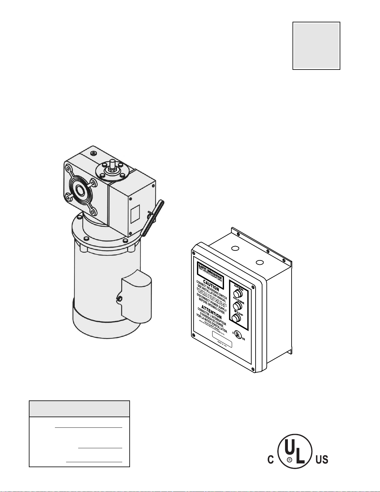
OWNER'S MANUAL
MODEL EGJ
EUROPEAN GEARHEAD CARWASH JACKSHAFT
NOT FOR RESIDENTIAL USE
LISTED DOOR OPERATOR
41B6
Serial #
(located on electrical box cover)
Installation Date
Wiring Type
2 YEAR WARRANTY
FACTORY SET
C2 Wiring
See page 6 for
other wiring
configurations
THE CHAMBERLAIN GROUP, INC.
ELMHURST, ILLINOIS 60126
PLACE RATING LABEL HERE
41B6
LISTED DOOR OPERATOR
Page 2
2
SPECIFICATIONS
MECHANICAL
DRIVE REDUCTION:.............45:1 Reduction
Hollow Shaft Gear.
OUTPUT SHAFT SPEED:.....39 R.P.M.
DOOR SPEED: ......................4 - 10" per sec.
depending on door
CLUTCH: ...............................Slipping Clutch
SAFETY
DISCONNECT:..............Floor level clutch disconnect with
electrical interlock for emergency manual door operation
CLUTCH: ......................Adjustable Slipping Clutch
REVERSING EDGE: ....(Optional) Electric or pneumatic
sensing device attached to the bottom edge of door.
A REVERSING EDGE IS STRONGLY RECOMMENDED FOR ALL COMMERCIAL OPERATOR INSTALLATIONS. REQUIRED WHEN THE 3 BUTTON CONTROL STATION IS OUT OF SIGHT OF DOOR OR
ANY OTHER CONTROL (AUTOMATIC OR MANUAL)
IS USED.
MOTOR
TYPE: .................................Gearhead Jackshaft.
HORSEPOWER: ................1/2, 3/4 & 1 Hp
Single or Three phase
SPEED:...............................1725 RPM
VOLTAGE:..........................115 & 230 Single phase
230 & 460 Three phase
CURRENT:..........................See motor nameplate
ELECTRICAL
TRANSFORMER:.............24VAC
CONTROL STATION:......NEMA 1 three button station.
OPEN/CLOSE/STOP
WIRING TYPE:.................C2 (Standard)
Momentary contact to OPEN/CLOSE/STOP plus wiring
for sensing device to reverse and auxiliary devices to
open and close with open override.
LIMIT ADJUST: ................Linear driven, fully
adjustable screw type cams. Adjustable to 30 feet.
BRAKE: ............................Dynamic brake,provides
.......................................electrical braking in the form
of DC current to stop the . motor.
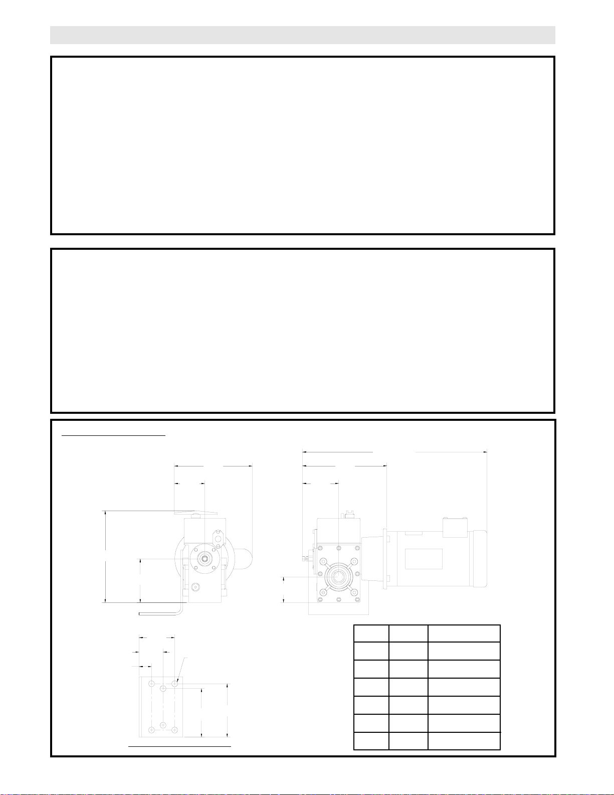
3.30”
EGJ DIMENSIONS
8.43”
4.73”
9.92”
See Chart
2.76”
3.94”
9.13”
5.75”
5.23”
1.36”
2.61”
3.86”
.630 DIA. HOLE
(4 PLACES)
MOUNTING DIMENSIONS
DIMENSION
1/2
3/4
1
1/2
3/4
1
1
1
1
3
3
3
21”
22”
23-5/16”
21-1/8”
22”
23-1/2”
HP
PHASE
Page 3
3
TO AVOID DAMAGE TO DOOR AND OPERATOR,
MAKE ALL DOOR LOCKS INOPERATIVE. SECURE
LOCK(S) IN "OPEN" POSITION.
IF THE DOOR LOCK NEEDS TO REMAIN FUNCTIONAL, INSTALL AN INTERLOCK SWITCH.
DO NOT CONNECT ELECTRIC POWER UNTIL
INSTRUCTED TO DO SO.
KEEP DOOR BALANCED. STICKING OR BINDING
DOORS MUST BE REPAIRED. DOORS, DOOR
SPRINGS, CABLES, PULLEYS, BRACKETS AND
THEIR HARDWARE MAY BE UNDER EXTREME TENSION AND CAN CAUSE SERIOUS PERSONAL
INJURY. CALL A PROFESSIONAL DOOR SERVICEMAN TO MOVE OR ADJUST DOOR SPRINGS OR
HARDWARE.
WARNING
CAUTION
WARNING
WARNING
WARNING
SITE PREPARATIONS
It is imperative that the wall or mounting surface provide adequate support for the operator. The safety and wear
of the operator will be adversely affected if any of the following requirements are not met.
a) Be rigid to prevent play between operator and door shaft.
b) Provide a level base.
c) Permit the operator to be fastened securely and with the drive shaft parallel to the door shaft.
IMPORTANT SAFETY NOTES
INSTALLATION INSTRUCTIONS
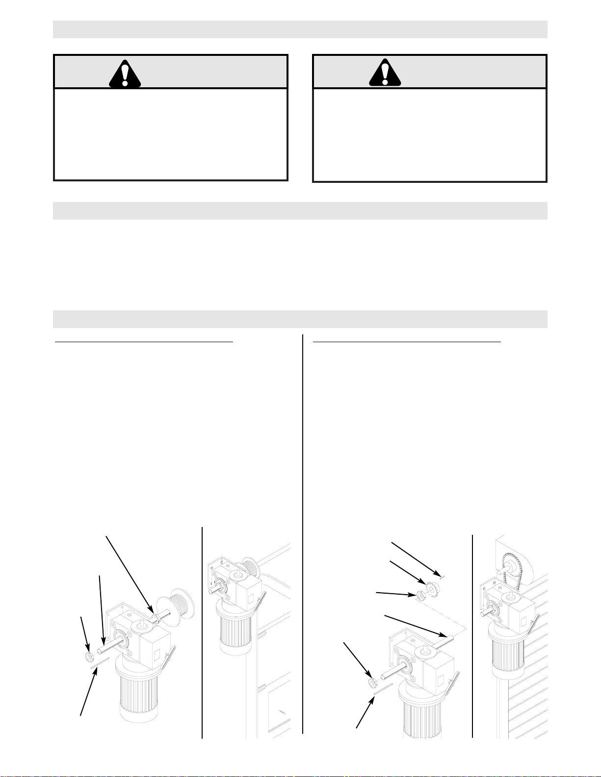
TYPICAL HOLLOW SHAFT INSTALLATION
1. Slide the shaft collar supplied over the door shaft to
desired position and secure in place.
2. Slide the operator on the door shaft until it is laying
against the shaft collar. Insert the 4-1/2” key supplied into
the operator and the door shaft.
4. Slide the second shaft collar on the door shaft until it is
laying against the operator and secure in place, this will hold
the 4-1/2” key in place.
5. Secure mounting bracket to wall (pad out as necessary).
NOTE: For additional help refer to the illustrations below.
OPTIONAL THOUGH-SHAFT INSTALLATION:
1. Slide the through shaft supplied into the operator to
desired position. Insert the 4-1/2” key supplied into the
operator and the door shaft.
2. Install a shaft collar onto each end of the through shaft
until they are laying against the operator and secure in
place, this will hold the 4-1/2” key in place.
3. Install the 12 tooth sprocket onto the though shaft with
the 1/1/2” key supplied.
4. Install the door sprocket supplied to the door shaft and
connect the operator to the door with chain supplied.
5. Secure mounting bracket to wall (pad out as necessary).
NOTE: For additional help refer to the illustration below.
12 Tooth Sprocket
1-1/2” key
Shaft Collar
4-1/2” Key
Shaft Collar
Through Shaft
Shaft
Collar
4-1/2” Key
Shaft Collar
Door
Shaft
CAUTION
WARNING
Page 4
4
SENSING EDGES
All types of sensing edges with an isolated normally open
(N.O.) output are compatible with your operator. This
includes pneumatic and electric edges. If your door does
not have a bottom sensing edge and you wish to purchase
one, contact the supplier of your operator.
If not pre-installed by the door manufacturer, mount the
sensing edge on the door according to the instructions provided with the edge. The sensing edge may be electrically
connected by either coiled cord or take-up reel. Refer to the
steps below.
Important Notes:
a) Proceed with Limit Switch Adjustments before making
any sensing edge wiring connections to operator as
described below.
b) Electrician must hardwire the junction box to the oper-
ator electrical box in accordance with local codes.
ENTRAPMENT PROTECTION ACCESSORIES (OPTIONAL)
IT IS STRONGLY RECOMMENDED THAT A
SENSING EDGE OR OTHER ENTRAPMENT
PROTECTION DEVICE BE USED IN CONJUNCTION WITH THIS OPERATOR.
TAKE-UP REEL: Take-up reel should be installed 12"
above the top of the door.
COIL CORD: Connect operator end of coil cord to junction
box (not supplied) fastened to the wall approximately
halfway up the door opening.
LIMIT SWITCH ADJUSTMENT
COARSE
ADJUSTMENT
FINE
ADJUSTMENT
CCW
CW
Lock Nut
Auxiliary Limit Switches
(When Supplied)
Adjustment Screw
Close Limit (Black)
Open Limit (Green)
LIMIT BOX ON POWERHEAD
THE LIMIT SWITCHES WILL STOP THE DOOR AT EACH
END OF TRAVEL. ADDITIONAL LIMIT SWITCHES CAN
BE USED FOR CONTROL OF OTHER AUTOMATIC
FUNCTIONS.
NOTE: Before stating adjustment of the limit switches,
loosen or tighten (if necessary) the lock nut in order to obtain
a convenient adjustment tightness of the cam wheels. After
finishing the adjustments, make sure that the lock nut is sufficiently tight to retain the cam wheels securely during operation.
When door is in the fully open position, the green cam wheel
(Open) will be turned into contact with its corresponding
switch. In the same way, just before the door is in the closed
position, the black cam wheel (Closed) will activate its
switch.
COARSE ADJUSTMENT
The coarse adjustment of the limit switches can be done by
inserting a rod or a screw driver into one of the adjustment
holes in the cam wheels and by turning each cam wheel with
the rod or screw driver.
FINE ADJUSTMENT
Fine adjustment can be done by screwing the adjustment
screw (supplied) against the cam shaft thread inside each
cam wheel. The screw must be changed from one adjustment hole into the other for turning the cam wheel in the
opposite direction.
Page 5

5
DISCONNECT POWER AT THE FUSE BOX BEFORE
PROCEEDING.
OPERATOR MUST BE PROPERLY GROUNDED AND
CONNECTED IN ACCORDANCE WITH LOCAL ELECTRICAL CODES. NOTE: THE OPERATOR SHOULD
BE ON A SEPARATE FUSED LINE OF ADEQUATE
CAPACITY.
ALL ELECTRICAL CONNECTIONS MUST BE MADE
BY A QUALIFIED INDIVIDUAL.
WARNING
TO AVOID DAMAGE TO DOOR AND OPERATOR,
MAKE ALL DOOR LOCKS INOPERATIVE. SECURE
LOCK(S) IN "OPEN" POSITION.
IF THE DOOR LOCK NEEDS TO REMAIN FUNCTIONAL, INSTALL AN INTERLOCK SWITCH.
1. Be sure that the power supply is of the correct voltage, phase, frequency, and amperage to supply the
operator. Refer to the operator nameplate on the
cover.
2. Using the 7/8” dia conduit access knockout as
shown below, bring supply lines to the wall mounted
starter and connect wires to the terminals indicated on
the WIRING CONNECTIONS DIAGRAM.
DO NOT TURN POWER ON UNTIL YOU HAVE FINISHED MAKING ALL POWER AND CONTROL
WIRING CONNECTIONS AND HAVE COMPLETED
THE LIMIT SWITCH ADJUSTMENT PROCEDURE.
CAUTION: THIS UNIT MUST BE PROPERLY
GROUNDED. A GROUND SCREW IS SUPPLIED IN
THE ELECTRICAL BOX FOR CONNECTION OF
THE POWER SUPPLY GROUND WIRE. FAILURE
TO PROPERLY GROUND THIS UNIT COULD
RESULT IN ELECTRIC SHOCK AND SERIOUS
INJURY.
Remove the cover from the wall mounted starter. Inside this enclosure you will find the wiring diagram(s)
for your unit. Refer to the wiring diagrams for all connections described below. If this diagram is missing,
call the number on the back of this manual. DO NOT INSTALL ANY WIRING OR ATTEMPT TO RUN THIS
OPERATOR WITHOUT CONSULTING THE WIRING DIAGRAM.
POWER WIRING
POWER WIRING CONNECTIONS
7/8” Dia Knockouts for
power wiring conduit access
7/8” Dia Knockouts for radio
conduit access
WARNING
Do Not Run Power &
Control Wiring in the
Same Conduit
7/8” Dia Knockouts for
control wiring & power head
conduit access
(2 on end panel)
WARNING
WARNING
THE CHAMBERLAIN GROUP, INC.
ELMHURST, ILLINOIS 60126
41B6
LISTED DOOR OPERATOR
PLACE RATING LABEL HERE
Page 6

6
CONTROL WIRING
Standard C2 or B2 Wiring
Standard operators are shipped from the factory with
jumper set for C2 wiring, which requires constant
pressure on button to close the door. If momentary
contact on close direction is desired (B2 wiring) you
must include an entrapment protection device. See
close control jumper setting below.
Constant pressure on close (C2 wiring)
Red jumper wire was placed on terminal #2 in
electrical enclosure. The operator will require
constant pressure on close control in order to keep
door moving in the close direction.
Momentary contact on close (B2 wiring)
Move red jumper wire from terminal #2 to terminal
#3. The operator will require only momentary
contact to close the door.
LOCATING THE CONTROL STATION
All operators are supplied with a three button station (OPEN/CLOSE/STOP) incorporated into the wall mounted
starter. Mount the wall mounted starter where the door is visible, but away from the door and its hardware.
WARNING
INSTALL THE WALL MOUNTED STARTER WHERE
THE DOOR IS VISIBLE, BUT AWAY FROM THE DOOR
AND ITS HARDWARE. IF STARTER CANNOT BE
INSTALLED WHERE DOOR IS VISIBLE, OR IF ANY
DEVICE OTHER THAN THE CONTROL STATION IS
USED TO ACTIVATE THE DOOR, A REVERSING EDGE
MUST
BE INSTALLED ON THE BOTTOM OF THE
DOOR. FAILURE TO INSTALL A REVERSING EDGE
UNDER THESE CIRCUMSTANCES MAY RESULT IN
SERIOUS INJURY OR DEATH TO PERSONS
TRAPPED BENEATH THE DOOR.
IMPORTANT: Mount WARNING NOTICE beside or
below the wall mounted starter.
MOUNT WARNING NOTICE
DETERMINE WIRING TYPE
Refer to the wiring diagram located on the inside cover the electrical box to determine the type of control wiring.
SPECIAL CONTROL WIRING
WIRING TYPES
If your operator was shipped from the factory with
non-standard control wiring or with optional accessories that require addition instructions, refer to the
wiring diagram(s) indicated in the special control
wiring data box. When a replacement wiring diagram
is present, wiring diagrams in this manual will not
apply. Refer only to the replacement wiring diagram
for all connections.
IMPORTANT NOTE: If your wiring diagram is
missing, or you are unsure of the wiring type for
your operator, contact the customer service
department @ 1-800-528-2806.
THE CHAMBERLAIN GROUP, INC.
ELMHURST, ILLINOIS 60126
WARNING
TO PREVENT ENTRAPMENT
DO NOT START DOOR DOWNWARD
UNLESS DOORWAY IS CLEAR
WARNING Notice
PLACE RATING LABEL HERE
41B6
LISTED DOOR OPERATOR
WARNING
Page 7

7
CONTROL WIRING (con’t)
Radio Controls
On all models with type B2 control wiring, a terminal
block marked R1 R2 R3 is located on the inside of the
wall mounted starter. All standard radio control
receivers (single channel residential type) may be
mounted to this terminal block. The operator will then
open a fully closed door, close a fully open door, and
reverse a closing door from the radio transmitter.
However, for complete door control from a transmitter,
a commercial three-channel radio set (with connections for OPEN/CLOSE/STOP) is recommended.
Additional Access Control Equipment
Locate any additional access control equipment as desired (but so that the door will be in clear sight of the person
operating the equipment), and connect to the terminal block in the electrical enclosure as shown on the FIELD
WIRING CONNECTIONS diagram. Any control with a normally (N.O.) isolated output contact may be connected
in parallel with the OPEN button. More than one device may be connected in this manner. Use 16 gauge wire or
larger for all controls. DO NOT USE THE CONTROL CIRCUIT TRANSFORMER (24VAC) IN THE OPERATOR TO
POWER ANY ACCESS CONTROL EQUIPMENT OTHER THAN A STANDARD RESIDENTIAL TYPE RADIO
RECEIVER.
External Interlock Switch
The operator has a terminal connection for an external interlock switch. This switch must be a normally closed
(N.C.) two-wire device with a contact rating of at least 3 amps @ 24VAC. When such a switch is connected as
shown on the FIELD WIRING CONNECTIONS diagram, the control circuit will be disabled when the switch is actuated, thereby preventing electrical operation of the door from the control devices.
WARNING
DO NOT USE RADIO CONTROLS WITH YOUR
OPERATOR UNLESS YOU HAVE INSTALLED
SOME TYPE OF ENTRAPMENT PROTECTION
DEVICE. THE USE OF RADIO CONTROLS PRESENTS POTENTIAL HAZARDS DUE TO THE
USER’S ABILITY TO OPEN OR CLOSE THE
DOOR WHEN OUT OF SIGHT OF THE DOOR. IN
ADDITION, IF A SINGLE CHANNEL CONTROL IS
USED, THE USER WILL NOT BE ABLE TO STOP
THE DOOR FROM THE TRANSMITTER.
WARNING
Page 8

8
ONE PHASE SCHEMATIC DIAGRAM
02228-1
GY
T1
T2
T3
T4
YE
PU
1
BL
3
8
5
4
2
115 VOLT - 1 PHASE
MOTOR CONNECTION
L2
POWER IN
1 PHASE
L1
(BK)
NOTE
1. IR RELAY COIL VOLTAGE IS THE SAME AS POWER IN
(WIRED N.O. HELD CLOSED WHEN MOTOR IS NOT RUNNING).
(BL)
STOP
(BL)
3
(YE)
OPEN
(BL)
(BL)
SAFETY EDGE
RADIO TO
OPEN & CLOSE
(OR)
R1
R1
(OR)
OPEN & CLOSE
CLOSE
CLOSE CONTROL WIRING OPTIONS
C2 WIRING - Constant Presssure to Close
*
RED WIRE ON TERMINAL #2 (Shipped from Factory)
B2 WIRING - Momentary Contact to Close
MOVE RED WIRE FROM TERMINAL #2 TO TERMINAL #3
- Shipped from Factory
*
TERMINAL IN WALL STARTERS
TERMINAL IN OPERATOR POWER HEAD
(WH)
(BK)
(SEE NOTE #1)
(RD)
OP
14
(YE)
R2
(OR)
OVERLOAD
IR
(BK)
(BK)
230V MODELS
115V MODELS
(WH)
PRI.
(BR)
16
1
NC
INTERNAL
INTERLOCK
8
EXTERNAL
INTERLOCK
45
10
(OR)
AUXILIARY
CLOSE LIMIT
SWITCH
7
C
(YELLOW)
13
(OR)
12
NC
7
11
C
NO
13
2
(PU)
(PU)
(PU)
(PU)
GY
T1
BL
T2
YE
T3
PU
T4
1
8
2
3
5
4
230 VOLT - 1 PHASE
MOTOR CONNECTION
(GY)
CL
OP
3
3
4
4
OP
2
6
(BK)
(BK) (BK)(WH) (WH)
IR
(OR)
AUX. OPEN
LIMIT SWITCH
1
CL
5
(PU)
230V PRIMARY
H1 H4H2H3 H1 H4H2H3
14
(OR)
13
TD1
(RD)
(YE)
(YE)
X1
8
R1
24 VAC
DPDT
(RED)
CLOSE LIMIT
SWITCH
11
4
C
(BLACK)
WITH 1-1/2 SEC. DELAY
(OR)
(RD)
WITH .1 SEC DELAY
83
53
IR
(RD)
OP
CL
13
(RD)
CL
TD1
(RD)
(PU)
14
84
(PU)
54
OP
5
CL
1
(GY)
OP
71
OP
61
24VAC
SEC.
OPEN LIMIT
SWITCH
1
C
NC
(GREEN)
5
NC
24VDC 3PDT
TD1
TD2
24V DC DPDT
6
2
72
62
X2
(YE)
2
(RD)
(PU)
12
(BL)
(PU)
(YE)
72
(GY)
62
(PU)
115V PRIMARY
(RD)
2A
9
(OR)
R1
(PU)
(WH)
(RD)
X4
A2
CL
CL
(WH)
A2
T1
T2
T4
T3
OP
71
61
TD-2
A1
CL
TO MOTOR
(GY)
(PU)
X3
(YE)
(YE)
(YE)
A1
-
+
(BL)
(YE)
TD-1
6
(RD)
R3
Page 9

9
1 PHASE FIELD CONNECTION DIAGRAM
IMPORTANT NOTES:
1) If a STOP button is not used, a jumper must be placed between terminals 3 and 4.
2) Auxiliary control equipment may be any normally open two wire device such as
pullswitch, single button, loop detector, card key or such device.
WALL MOUNTED STARTER
SEPERATE 3 BUTTON STATION
OTHER THAN ONE SUPPLIED
ON WALL MOUNTED STARTER
STOP ON
WALL MOUNTED
STARTER
RED WIRE ORIGINALLY WENT TO
TERMINAL 4 IN STARTER
EXTERNAL INTERLOCK
OPEN
CLOSE
STOP
OPEN & CLOSE
12
1
13
2
3
4
5
REMOVE JUMPER
IF EXTERNAL
SWITCH IS USED
16
6
11
7
8
(GREEN)
1
ATTENTION ELECTRICIAN:
USE 16 GAUGE OR HEAVIER WIRE
FOR ALL CONTROL CIRCUIT WIRING.
POWERHEAD LIMIT BOX
8
AUXILIARY OPEN
LIMIT SWITCH
(RED)
OPEN LIMIT SWITCH
SAFETY EDGE
RADIO
RECEIVER
1 PHASE
POWER IN
2
9
10
11
12
13
7
4
5
14
(YELLOW)
(BLACK)
AUXILIARY CLOSE
LIMIT SWITCH
CLOSE LIMIT SWITCH
INTERNAL INTERLOCK
SWITCH
14
3
2
1
R3
R2
R1
T1
T2
MOTOR
(SEE SCHEMATIC)
T3
T4
L1
L2
L3
GROUND
Page 10

10
THREE PHASE SCHEMATIC DIAGRAM
02228-3
4
3
5
6
1
2
4
3
2
1
6
5
L3
(GY)
(PU)
(YE)
EXTERNAL
STOP
3
45
24VAC
SEC.
PRI.
1
7
10
OPEN
SAFETY EDGE
OPEN & CLOSE
LIMIT SWITCH
(RED)
AUX. OPEN
C
NO
NC
TO MOTOR
POWER IN
L2
3 PHASE
INTERLOCK
OP
R1
OP
OP
CL
CL
OP
CL
OP
14
13
R1
OPEN & CLOSE
R2
R1
CLOSE
2
CL
(BK)
(BR)
(YE)
(OR)
(RD)
(RD)
(YE)
(PU)
(BL)
RADIO TO
A1
A2
A2
A1
C
NC
INTERNAL
INTERLOCK
(BR)
T1
T2
T3
T3
T2
T1
14
16
14
13
(BL)
(RD)
(BL)
OPEN LIMIT
SWITCH
1
2
9
(YE)
(OR)
(GREEN)
24 VAC
DPDT
(YE)
R3
6
(RD)
C
NC
AUXILIARY
CLOSE LIMIT
SWITCH
7
8
(YELLOW)
(OR)
(OR)
(YE)
(OR)
(OR)
11
13
12
(BL)
C
NC
5
(BLACK)
CLOSE LIMIT
SWITCH
(PU)
R1
(PU)
12
TERMINAL IN WALL STARTERS
TERMINAL IN OPERATOR POWER HEAD
OVERLOAD
(WHEN SUPPLIED)
L1
(BK)
(BK)
(BR)
(BR)
(BR)
14
(BR)
MOTOR OVERLOAD
OR OVERLOAD PILOT
2
3
1
6
9
4
7
85
2
3
YEL
BRN
BRN
PUR
GY
1
6
9
OVERLOAD
(WHEN SUPPLIED)
4
7
85
230 VOLT - 3 PHASE
MOTOR CONNECTION
460 VOLT - 3 PHASE
MOTOR CONNECTION
13
T3
T2
T1
14
YEL
BRN
BRN
PUR
GY
13
OVERLOAD
(WHEN SUPPLIED)
(BK)
(BK)
(BK)
OP
71
72
OP
61
62
CL
72
71
CL
62
61
(PU)
(PU)
(GY)
(PU)
(GY)
+
-
(BR) (BR)(BR) (BR)
H1 H4H2H3 H1 H4H2H3
TD-2
TD-1
X4
X3
(RD)
(YE)
(YE)
(BL)
460V PRIMARY
230V PRIMARY
8
(OR)
(YE)
TD1
4
11
(PU)
(RD)
TD1
CL
(PU)
(RD)
*
- Shipped from Factory
OP
83
84
CL
53
54
(PU)
(PU)
(PU)
TD2
TD1
(OR)
(RD)
(WH)
(RD)
24VDC 3PDT
WITH 1-1/2 SEC. DELAY
24V DC DPDT
WITH .1 SEC DELAY
C2 WIRING - Constant Presssure to Close
RED WIRE ON TERMINAL #2 (Shipped from Factory)
B2 WIRING - Momentary Contact to Close
MOVE RED WIRE FROM TERMINAL #2 TO TERMINAL #3
CLOSE CONTROL WIRING OPTIONS
*
13
14
(WH)
2A
Page 11

11
3 PHASE FIELD CONNECTION DIAGRAM
IMPORTANT NOTES:
1) If a STOP button is not used, a jumper must be placed between terminals 3 and 4.
2) Auxiliary control equipment may be any normally open two wire device such as
pullswitch, single button, loop detector, card key or such device.
WALL MOUNTED STARTER
SEPERATE 3 BUTTON STATION
OTHER THAN ONE SUPPLIED
ON WALL MOUNTED STARTER
STOP ON
WALL MOUNTED
STARTER
RED WIRE ORIGINALLY WENT TO
TERMINAL 4 IN STARTER
EXTERNAL INTERLOCK
OPEN
CLOSE
STOP
OPEN & CLOSE
1
1
4
2
3
4
5
REMOVE JUMPER
IF EXTERNAL
SWITCH IS USED
16
6
11
7
8
(GREEN)
(BLACK)
(RED)
ATTENTION ELECTRICIAN:
USE 16 GAUGE OR HEAVIER WIRE
FOR ALL CONTROL CIRCUIT WIRING.
POWERHEAD LIMIT BOX
8
12
OPEN LIMIT SWITCH
CLOSE LIMIT SWITCH
13
AUXILIARY OPEN
LIMIT SWITCH
SAFETY EDGE
RADIO
RECEIVER
3 PHASE
POWER IN
2
9
10
7
(YELLOW)
AUXILIARY CLOSE
LIMIT SWITCH
11
5
12
13
14
INTERNAL INTERLOCK
SWITCH
14
TO MOTOR OVERLOAD
3
2
1
R3
R2
R1
WHEN SUPPLIED
T1
T2
MOTOR
(SEE SCHEMATIC)
T3
T4
L1
L2
L3
GROUND
Page 12

12
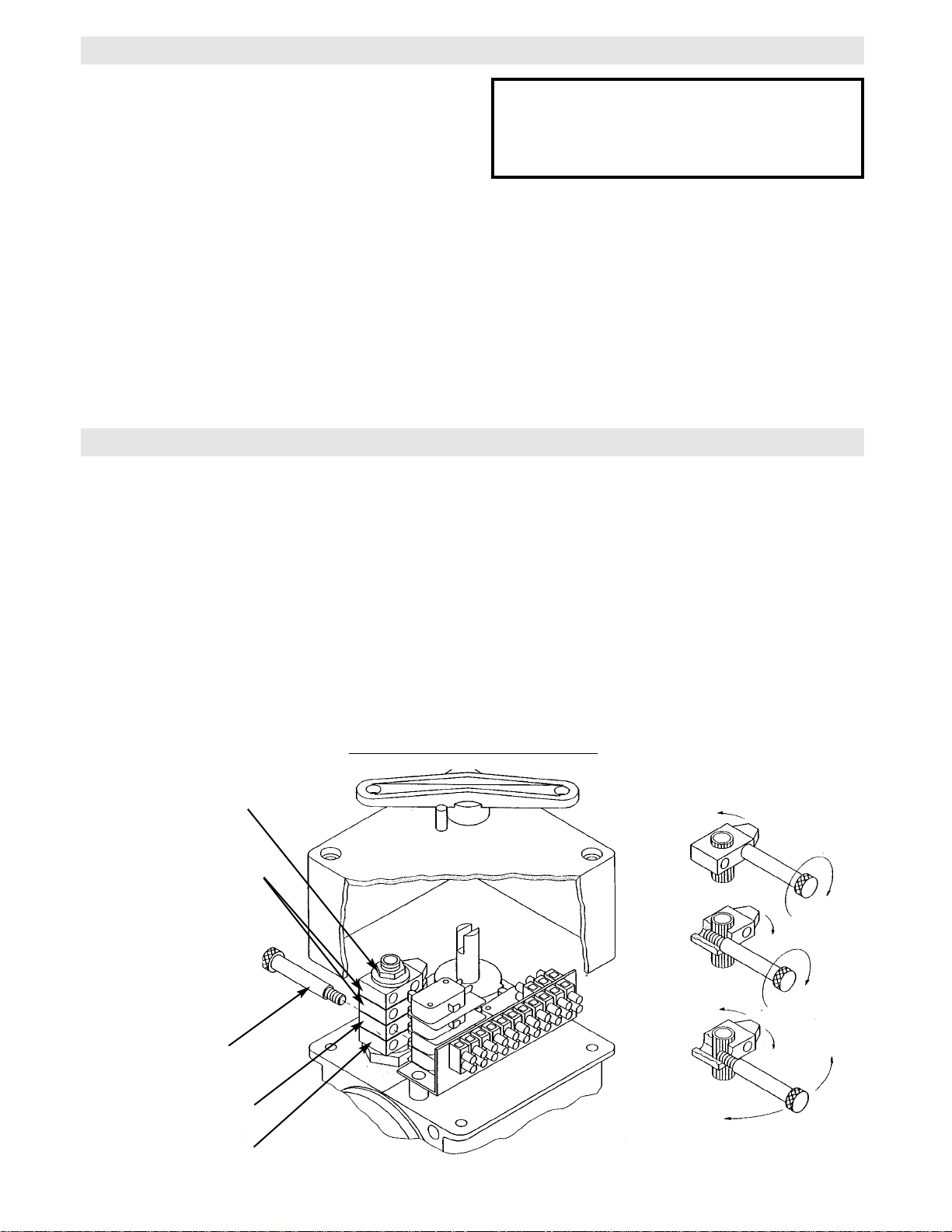
SLIPPING CLUTCH ADJUSTMENT
The torque transmitted by the drive unit must always
be adjusted in due consideration of the safety requirements of the door operation. The limitation of the
torque is done by adjusting the slipping clutch situated
between the electric motor and the gear box.
When delivered from the factory the slipping clutch is
left loose so that no torque can be transmitted from
the electric motor.
Adjustment:
1. Loosen the lock nut at the end of the worm shaft.
2. Hold the worm shaft with a spanner.
3. Start turning the adjustment screws inwards (=
clockwise) until the required torque has been
obtained.
The torque should be adjusted so that it is just high
enough to move the door over its complete travel and
low enough to permit the clutch to slip as soon as the
door is obstructed in its movement. A direct safety risk
is produced if the torque is set to a considerably higher level than required for the door operation.
IMPORTANT: Before starting to adjust the slipping
clutch, check and make sure that the door can easily
be moved manually in every part of its travel.
WORM SHAFT
LOCK NUT
ADJUSTMENT SCREW
CLUTCH LINING
WARNING
DO NOT PLACE HANDS OR TOOLS IN OR NEAR
THE OPERATOR WHEN THE POWER IS ON.
ALWAYS DISCONNECT POWER BEFORE SERVICING OR ADJUSTING THE OPERATOR.
WARNING
Page 13

13
MANUAL DISCONNECT
By turning the disengagement lever the gear unit can
be disconnected from electric operation in order to
permit manual operation of the door. For operating
the lever from above floor level, attack a rope or a
chain in the holes at the ends of the lever.
The movement of the lever acts upon a safety micro
switch, which will keep the control current disconnected until the lever has been turned absolutely perfectly
into its position for normal electric operation of the
door.
DISENGAGEMENT LEVER
TO DISENGAGE PULL HAN-
TO ENGAGE PULL HANDLE
Page 14

14
TEST THE SYSTEM
Turn on power. Test all controls and safety devices to
make sure they are working properly. It will be necessary to refer back to page 6 for fine adjustment of the
limit switches.
IMPORTANT NOTES:
Do not leave operator power on unless all safety
and entrapment protection devices have been
tested and are working properly.
Be sure you have read and understand all Safety
Instructions included in this manual.
Be sure the owner or person(s) responsible for
operation of the door have read and understand
the Safety Instructions, know how to electrically
operate the door in a safe manner, and know how
to use the manual disconnect operation of the
door operating system.
WARNING
DO NOT PLACE HANDS OR TOOLS IN OR NEAR
THE OPERATOR WHEN THE POWER IS ON OR
WHEN TESTING CONTROL OR SAFETY
DEVICES. ALWAYS DISCONNECT POWER
BEFORE SERVICING OR ADJUSTING THE
OPERATOR.
WARNING
Page 15

15
HOW TO ORDER REPAIR PARTS
OUR LARGE SERVICE ORGANIZATION
SPANS AMERICA
INSTALLATION AND SERVICE INFORMATION
ARE AVAILABLE 6 DAYS A WEEK
CALL OUR TOLL FREE NUMBER - 1-800-528-2806
HOURS 7:00 TO 3:30 p.m. (Mountain Std. Time)
MONDAY Through SATURDAY
WHEN ORDERING REPAIR PARTS
PLEASE SUPPLY THE FOLLOWING INFORMATION:
PART NUMBER DESCRIPTION MODEL NUMBER
ADDRESS ORDER TO:
THE CHAMBERLAIN GROUP, INC.
Electronic Parts & Service Dept.
2301 N. Forbes Blvd., Suite 104
Tucson, AZ 85745
MAINTENANCE SCHEDULE
* Use SAE 30 Oil (Never use grease or silicone spray).
Repeat ALL procedures.
Do not lubricate motor. Motor bearings are rated for continuous operation.
Inspect and service whenever a malfunction is observed or suspected.
CAUTION: BEFORE SERVICING, ALWAYS DISCONNECT OPERATOR FROM POWER SUPPLY.
Check at the intervals listed in the following chart.
EVERY EVERY EVERY
ITEM PROCEDURE 3 MONTHS 6 MONTHS 12 MONTHS
Drive Chain Check for excessive slack.
Check & adjust as required.
Lubricate.*
z
3
Sprockets Check set screw tightness
z
3
Fasteners Check & tighten as required
z
3
Manual Disconnect Check & Operate
z
3
Bearings & Shafts Check for wear & lubricate
z
3
Page 16

16
REPAIR PARTS KITS – WALL MOUNTED STARTER
* COMPLETE ELECTRICAL BOX KITS
Item
1
2
3
4
5
6
7
8
9
10
11
12
13
14
15
16
17
18
19
20
Description
CONTACTOR
PANEL, EGJ
(SEE VARIABLE CHART)
RELAY, R1
RELAY, TD1
RELAY, TD2
(SEE VARIABLE CHART)
(SEE VARIABLE CHART)
(SEE VARIABLE CHART)
CONTACT BLOCK
BRIDGE RECTIFIER
BLACK BUTTON
BLACK BOOT
RED BUTTON
RED BOOT
10 POLE TERMINAL BLOCK
14 POLE TERMINAL BLOCK
ENCLOSURE
FUSE HOLDER
2A FUSE
Qty
1
1
1
1
1
1
1
1
1
2
1
1
1
2
2
1
1
1
1
1
P/N
03-8024K
10-15598
21-7XXX
24-24-1
24-24-03
24-264-4
24-XXXX
25-2XXX
25-4XXX
27-8004-K
29-448
30-100-E
30-105-E
30-200-E
30-205-E
42-110
42-114
44-1210-4XH
27-58301-01
29-ABC-2
Below are replacement kits available for your operator. For replacement of wall mounted starter and or motor kit be sure to
match model number of your unit to kit number below to ensure proper voltage requirements. Optional modifications and/or
accessories included with your operator may add or remove certain components from these lists. Please consult a parts and
service representative regarding availability of individual components of kits specified below. Refer to page 15 for all repair
part ordering information.
Complete Electrical Box Replacement Kits
To order a complete electrical box replacement kit, add a K-
prefix to the model number of your operator. For example:
EGJ5011M (Operator) = K-EGJ5011M (Elec. Box Kit)
Motor Kits
20-1050C2T Models EGJ5011M & EGJ5021M
20-1075C2T Models EGJ7511M & EGJ7521M
20-1100C2T Models EGJ1011M & EGJ1021M
20-3050C4T Models EGJ5023M & EGJ5043M
20-3075C4T Models EGJ7523M & EGJ7543M
20-3100C4T Models EGJ1023M & EGJ1043M
P/N
21-7115
21-7460
24-115-1
24-230-5
25-2006
25-2008
25-2010
25-2015
25-4002-5K
25-4004-K
Item
3
7
8
9
Description
TRANSFORMER, 115/230V 1 PHASE
TRANSFORMER, 230/460V 3 PHASE
RELAY, 115V
RELAY, 230V
OVERLOAD, 6 AMP
OVERLOAD, 8 AMP
OVERLOAD, 10 AMP
OVERLOAD, 15 AMP
OVERLOAD, 1.6 - 2.5 AMP
OVERLOAD, 2.5 - 4.0 AMP
EGJ5011M
EGJ5021M
EGJ5023M
EGJ5043M
EGJ7511M
EGJ7521M
EGJ7523M
EGJ7543M
EGJ1011M
EGJ1021M
EGJ1023M
EGJ1043M
Page 17

17
ILLUSTRATED PARTS – WALL MOUNTED STARTER
5
10
8
9
4
1
14
13
15
11
2
18
12
17
7
6
3
16
19
20
Page 18

18
REPAIR PARTS KITS – MODEL EGJ (TYPICAL HOLLOW SHAFT)
Refer to the parts lists below for replacement kits available for your operator. If optional modifications and/or
accessories are included with your operator, certain components may be added or remove from these lists.
Individual components of each kit may not be available. Please consult a parts and service representative regarding availability of individual components. Refer to page 15 for all repair part ordering information.
INDIVIDUAL PARTS
ITEM PART # DESCRIPTION QTY
1
2
3
4
5
6
7
8
MOUNTING BRACKET
SHAFT COLLAR
PULL CORD
PULL SWITCH HANDLE
KEY, 1/4” X 4-1/2” LONG
LIMIT GEAR REDUCER
MOTOR
WALL MOUNTED STARTER
1
2
2
2
1
1
1
1
10-9097
13-10465
19-02411
50-13507
80-13713
TVR-4-1
See Page 16
See Page 16
1
2
5
6
2
7
8
4
3
Page 19

T1
ILLUSTRATED PARTS – MODEL EGJ (OPTIONAL THROUGH SHAFT)
19
Refer to the parts lists below for replacement kits available for your operator. If optional modifications and/or accessories are included with your operator, certain components may be added or remove from these lists. Individual
components of each kit may not be available. Please consult a parts and service representative regarding availability
of individual components. Refer to page 15 for all repair part ordering information.
INDIVIDUAL PARTS
ITEM PART # DESCRIPTION QTY
1
2
3
4
5
6
7
8
MOUNTING BRACKET
SHAFT COLLAR
PULL CORD
PULL SWITCH HANDLE
KEY, 1/4” X 4-1/2” LONG
LIMIT GEAR REDUCER
MOTOR
WALL MOUNTED STARTER
1
2
2
2
1
1
1
1
10-9097
13-10465
19-02411
50-13507
80-13713
TVR-4-1
See Page 16
See Page 16
THROUGH SHAFT KIT, 71-13716
ITEM PART # DESCRIPTION QTY
T1
T2
T3
THROUGH SHAFT
SPROCKET, 50B12 1” BORE
KEY, 1/4” X 1-1/2” LONG
1
1
1
11-13717
15-50B12LGH
80-207-19
1
T3
T2
2
5
6
2
4
8
3
7
Page 20

c
2000, The Chamberlain Group, Inc.
All rights Reserved
01-15044D
 Loading...